... laser operat- ing above threshold is given by using the rate-equation model. ... feedback laser diode, for wavelength conversion, optical-signal amplification ...
2026
JOURNAL OF LIGHTWAVE TECHNOLOGY, VOL. 11, NO. 12,DECEMBER 1993
Optical Frequency Conversion Using Nearly Degenerate Four-Wave Mixing in a Distributed-Feedback Semiconductor Laser: Theory and Experiment Rongqing Hui, Sergio Benedetto, and Ivo Montrosset Abstract-An analytical description of nearly degenerate conversion [7]-[ 111. The effective frequency-conversion four-wave mixing in a single-mode semiconductor laser operat- bandwidth using FWM in a TWA is limited by the inverse ing above threshold is given by using the rate-equation model. The theoretical result is confirmed by the experiment measuring of the effective carrier lifetime of the laser amplifier, the power amplification of probe and conjugate waves. A which is usually less than 5-6 GHz with positive gain [SI. 155-Mb/ s frequency-shiftkeying optical-transmissionsystem is Furthermore, in this scheme an external pump source demonstrated using four-wave mixing in a bulk distributed- with high optical power is required. The frequency-confeedback laser diode, for wavelength conversion, optical-signal version bandwidth has been effectively extended to 4000 amplification, and data up-streaming.
GHz by using simultaneously two external pump waves injected into a TWA [12], at the expense of an increased system complexity. In the case of FWM in self-oscillating I. INTRODUCTION laser diodes, however, the pump wave is generated by H E PHENOMENA of four-wave mixing (FWM) and itself and the FWM efficiency is enhanced enormously by nearly degenerate four-wave mixing (NDFWM) have the cavity feedback. Highly nondegenerate FWM using an attracted considerable attention in nonlinear optics [l], injection-locked nearly single-mode laser diode has been [2]. The possibility of wavelength conversion using FWM demonstrated in an optical-communication system for is also promising in optical-communication systems with wavelength conversion [131, where the probe and the frequency-domain multiple access (FDMA). Apart from conjugate waves have been enhanced by the cavity resothe prerequisite of using nonlinear material, optical gain nance at the side longitudinal modes and the wavelength and cavity feedback can also play an important role in conversion range can be as high as terahertz (noncontinuachieving higher conjugate amplification, since the nonlin- ous). On the other hand, NDFWM is suitable in the ear susceptibility involved in the FWM process can be application of dense FDMA systems. In a laser diode strongly enhanced by the optical gain and the cavity operating above threshold, the effective NDFWM bandfeedback. Collinear intracavity FWM in a semiconductor width is determined by the laser’s relaxation oscillation laser has been reported [31, [4], and the conjugate ampli- and a frequency conversion of up to 30 GHz can be fication of up to 30-40 dB has been obtained. The physi- achieved; this value is much higher than the NDFWM cal mechanism behind the phenomenon of NDFWM was bandwidth in a TWA. However, its application in optical explained by the theory of dynamic population pulsation communication systems has received only limited attenat the beat frequency of the intracavity propagated waves tion [14]. [5]. This description is equivalent to a description in terms In this paper, a theoretical investigation of collinear of creating gain and refractive-index gratings in the spatial NDFWM in a single-mode semiconductor laser using a domain. More recently, FWM in travelling-wave laser rate-equation model is presented. The theoretical results amplifiers (TWA) also has been extensively studied [6], [71. agree qualitatively with the experimental data. Using a FWM gives rise to the interference between different 155-Mb/s frequency-shift keying (FSK) optical transmischannels when a TWA is implemented in a multichannel sion system, we demonstrated the use of NDFWM in a optical-communication system. On the other hand, FWM DFB laser diode operating above threshold, for frequency in a TWA can also be utilized to achieve frequency conversion, optical-signal amplification, and data upstreaming.
T
Manuscript received January 25, 1993; revised May 17, 1993. Work supported by CNR and Camera di Cornmercio di Torino under research grant “All-Optical Communication Networks,” Italian Ministry for the University and Science and Technological Research (MURST), and by NATO research grant CRG 910309. The authors are with Dipartimento di Elettronica, Politecnico di Torino, c.so Duca degli Abruzzi 24, 10129 Torino, Italy. IEEE Log Number 9212973. 0733-8724/93$03.00
11. THEORETICAL ANALYSIS
The theory of FWM in semiconductor laser devices has already been developed [5]. Even though the analysis in that paper is general, most of the attention is devoted to the discussion of FWM in TWA’s. In semiconductor lasers 0 1993 IEEE
HUI
et
2027
al.: OPTICAL FREQUENCY CONVERSION
operating above threshold, the FWM efficiency is modified by the cavity resonance and a theory more relevant to this case is required. In the state-of-art technology, semiconductor lasers usually work in one fundamental transverse mode and, in addition, newly developed laser structures like distributed feedback (DFB) and distributed Bragg reflector (DBR) can provide a strong longitudinal mode selection. If we further neglect the spatial inhomogeneities and the carrier-diffusion effect, the carrier population N in the active cavity will obey the simple rate equation
Substituting (21-44) into (1) and neglecting high-order quantities, we get the expressions
(6)
where P, = l/(uT,) is the saturation optical power and IE,I2 = IE,I2 + /Ell2+ IE,I2 is the stationary optical power. In the equilibrium state, the optical gain should be compensated by the loss in the laser cavity. Then
where C is the carrier injection rate, E is the electric field normalized as the square root of the photon density inside g(N,, IE,I’) = a ( N , - No>(’ - EIE,I2) = l/Tp, the laser’s activity cavity, T, is the effective carrier recomwhere T- is the photon lifetime. bination lifetime, and g is the material gain. The material gain g(N,IEI2) can be expanded, in a Generally, the nonuniform intensity distribution and Taylor series, around the stationary-state operating point thus the spatial-hole-burning effect in the longitudinal as direction of the laser cavity may play an important role. Here, however, we use the mean-field approximation for g ( N , lEI2)= l / T p -+ U(1 - EIE,I2)(N- N,) simplicity. - U E W , - N0)(IE12 - lE,I2). We consider the NDFWM in a laser diode operating above threshold which, by itself, provides the pump wave The electric field inside the cavity of the pump laser can while the probe wave is externally injected from a master be described by the usual Van der Pol equation with an additional term representing the external optical injection laser. The total intracavity field can be expressed as [ 151: dE(t) - U [ (1 dt
--
where o is the optical frequency of the pump wave and E ( t ) = E,
+ E , exp ( i f i t ) + E , exp ( -iRt)
-
ElE,l2)(N
-
N,) - i P ( N
-
N,)
(2)
with E,, E,, and E , the field amplitude of pump, probe, and conjugate waves, respectively. Cl is the pump-probe frequency detuning. In the small-signal analytical approach adopted here, we assume that both [Elland lE21 are much smaller than lEol,which is usually the case when the pump laser is biased at high level. In this approximation, however, harmonics of orders higher than 1 are automatically neglected. The material gain of the pump laser is assumed to vary with the carrier population and to be affected by the nonlinear gain saturation:
where P is the well known linewidth enhancement factor of the pump laser, Eiis the amount of the external field coupled into the active cavity of the pump laser, and T~ is its cavity averaging factor, which can be approximated by the cavity roundtrip time 2nL/c with L the cavity length, n the effective refractive index, and c the light speed. Substituting (2)-(6) into (7) and separating terms containing exp ( - i f l t ) and exp (iflt), we obtain -iREl
=
iEoi2iEli+ E;E: -
2TP(l - ‘IE,I’)P, (1 - €1E,1’ - i P ) ( l - 2tlEUl2)
1 + IE, I ~/ P , where a is the differential gain, No is the transparency carrier density, and E is the nonlinear gain coefficient. Using the same approximation as used in (21, the carrier density can be expressed as N
= N,
+ A N e x p ( - i a t ) + AN* exp(ilRt),
(4)
where N, is the static carrier population, A N accounts for the carrier population pulsation [51, and the asterisk (*I designates the complex conjugation.
- ia7,
+
E.]
(8)
JOURNAL OF LIGHTWAVE TECHNOLOGY, VOL. 11, NO. 12, DECEMBER 1993
2028
Equations (8) and (9) can be written in a simple matrix form:
and
where the matrix elements are 1
(1 - €IE,I2 - i p ) ( 1
.[
M,,
=
1
2€lE,12)
+ IE,12/P, - inr,
]
+ Er,
1
-in + *[
-
27-(1 - E l E , 1 2 ) (1 - €IE,12 + i P ) ( l - 2€1E,12) 1 + IE,I2/P, - iQ7,
and Ci= Ei/r The probe wave-field amplification
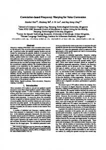
where Po = IE,12/P, is the normalized optical power and SLi = IEo12g(Ns,IE,l2)/(~,P,) is the square of the relaxation oscillation angular frequency of the pump laser [161. IEOl2 The power amplification for the probe wave (lA,I2) and ps the conjugate wave (lA,I2) has been calculated for different bias levels of the pump laser; the results are shown in Fig. 1. In Fig. l(a), the pump laser is biased at a higher level with Po = 3.5, whereas in Fig. l(b), the pump laser is biased at a lower level with Po = 1.1. Other parameters used in the calculation are p = 5 , a = 7 X lo3 s-l, g(N,, lE,I2) = 9 x 10" s-', a . E = 6.2 X lo4, T~ = 0.8 ns, and T~ = 8 ps. Comparing Fig. l(b) with Fig. l(a), it is evident that the (12) effective FWM bandwidth increases with the increase of the optical power of the pump laser, and at the same time the resonant peaks corresponding to the frequency of the relaxation oscillation are more damped because of the nonlinear gain saturation. In both cases, the conjugate amplification, defined by the conjugate power output divided by the probe power input, is similar to the probe (13) amplification. Both the probe and the conjugate amplification are almost symmetric with respect to the zero detuning. These results are very different from those related to the FWM in TWAs [5]. It must be pointed out that, here, the effect of pump depletion is not included, because our analysis is limited to the small signal case. Pump depletion usually happens (14) when the injected optical power is high enough, or the frequency detuning between the probe and the pump is too small, especially when the pump laser is biased at low levels.
(15) and the conjugate wave-field amplification (16)
can be obtained easily from (10). The parameters in (15) and (16) are expressed as
U,
=
-in(l
+ Po - ZnT,)
[(l - elE,I2
U,
=
-
+ ip)(l
-
2~lE,l~)
[(1 - €lE,12 + i P ) ( l - 2€IE,12) + €PJ1 + Po - inTJ] 2TP(1 - €lE,I2)
, (18)
111. EXPERIMENTS
In this part we present our experimental measurements on the probe and conjugate power amplification and demonstrate a FSK transmission system using the multifunction of FWM. The experimental setup is shown in Fig. 2. Two identical commercial DFB-BH laser diodes with an emission wavelength of 1546 nm are used. One of them (LD1) is used as the probe with its output injected through a variable optical attenuator into the other laser (LD2). This laser works well above threshold because the FWM element provides the pump wave. The injected probe light is amplified inside the active cavity of the FWM element and the wavelength-converted conjugate wave is created. These optical signals are sent to the receiver through another optical attenuator (VATZ). At the receiver side, a tunable external cavity semiconductor laser (LD3) is used as the local oscillator in the heterodyne system, down-shifting the optical frequency to IF
2029
HUI et al.: OPTICAL FREQUENCY CONVERSION PC
Isolator
0001
LD3
I
35 -
FDC
30-
T 0’
-15
-5
-10
0
5
10
I
I
I
15
Frqucncy &tuning (GHz)
(a) (Modulation
I
Fig. 2. Experimental setup LD, laser diodes; PC, polarization control; FDC, fiber directional coupler; VAT, variable attenuators; BS, beam splitter.
Frequency deluning (GHz)
(b)
Fig. 1. Small-signal probe and conjugate wave amplifications with the pump laser biased at different levels: (a) I = 40 m~ in the experiment and Po =. 3.5 in the calculation; (h) Z = 25 mA in the experiment and Po = 1.1 m the calculation. The pump laser has the threshold current of 18 mA. Probe and conjugate amplifications are represented by open circles (solid lines) and crosses (dashed lines), respectively, for the experimental (theoretical) results.
range. The signal is then measured in a 22-GHz wideband spectrum analyzer with the lightwave section performing photodetection. A. Measurement of the F W Bandwidth The probe and the conjugate wave amplification are evaluated from the measured optical spectrum on the spectrum analyzer. The optical power that is actually injected into the FWM element is estimated through the measured injection-locking bandwidth B by the formula Pi= (2.rrB~~)’P/(l p ’ ) [171, where P is the optical power of the pump laser while the linewidth enhancement factor p has been measured to be 5 using the method presented in [lSI. Instead of measuring only the peak amplitude, we measured the output power of the probe and the conjugate waves by integrating over a certain frequency range around each peak on the spectrum. The
+
advantage of this integration is that the result is not affected by the linewidth. In fact, the linewidth of the conjugate wave is usually much wider than the probe wave [19]. If only the peak amplitudes are measured, the conjugate amplification will be underestimated as the result previously reported in [41. We measured the probe and the conjugate amplification when the pump laser was biased at two different levels: Z = 40 mA [Fig. l(a)] and Z = 25 mA [Fig. l(b)l. The threshold current of this laser is about Zth = 18 mA. The measured results are plotted in the same figure with the theoretically calculated results. Suppose that the Optical power is linearly proportional to the normalized current ( I - zth),zth; then the bias conditions of the pump laser in the experiment are proportional to those used in the calculations. A qualitative agreement between the theory and the experiment is obvious. In the case when the pump laser is biased at high level [Fig. l(a)l, the effective FWM bandwidth (with positive conjugate gain) easily can be extended to more than k 15 GHz. This value is much larger than the NDFWM bandwidth in travelingwave laser amplifiers, where this bandwidth is mainly determined by the inverse of the carrier lifetime and is usually no more than + 6 GHz [5],[8]. From this result, it appears that the NDFWM in a laser diode operating above threshold is suitable to perform the wavelength conversion function in an optical frequency division multiplexing (OFDM) system. B. Optical FSK Transmission System Experiment In this part we report our FSK optical transmission system experiment using NDFWM in a commercial DFB laser diode. Multifunctional applications of FWM in a laser diode makes it a possible candidate as a node in a
JOURNAL OF LIGHTWAVE TECHNOLOGY, VOL. 11, NO. 12, DECEMBER 1993
2030
transmission system performing optical amplification, frequency conversion, and signal data up-streaming. The possible applications are demonstrated as follows. In the first operating mode, the signal is applied to the probe laser (LDl), which works as the transmitter. The FWM element (LD2) works in the continuous-wave (CW) condition; it amplifies the incoming FSK-modulated optical signal from the transmitter and generates the frequency-converted conjugate wave. A typical heterodyne spectrum in this operating mode is shown in Fig. 3(a); in this case, the signal is converted from the probe to the conjugate wave, and a consequent wavelength conversion of 18 GHz. In the optical-transmission experiment, the pump laser is biased at the level I = 40 mA, corresponding to the FWM characteristic shown in Fig. l(a), so that both the probe and the conjugate amplification are approximately 22 dB with the used frequency detuning. This configuration seems promising in network applications also because it is possible to broadcast simultaneously the same signal, after the amplification, to two different nodes addressed by different wavelengths. In another operating mode, LD1 is not modulated and a direct FSK modulation is applied to the FWM element (pump laser). Since the carrier density is modulated, this up-streamed signal can also be converted from the pump to the conjugate wave as illustrated by the spectrum of Fig. 3(b). In both cases, the spectra of the conjugate waves are the same. This permits use of a unique receiver structure as in Fig. 2. It is interesting to notice that the frequency-modulation index is the same for the probe and the conjugate waves in the first operating mode, while in the second operating mode, the modulation index of the conjugate wave is twice the modulation index of the pump (see Fig. 3). This simple relationship can be understood quickly through (16). If the probe light is frequency-modulated, obviously, the conjugate wave is frequency-modulated with the same modulation index. However, the FM modulation to the pump will double the FM modulation index in the conjugate wave through the square-law relationship in (16). It is worth noting that the relationship between the modulation index of the probe, pump, and conjugate waves is different from their linewidth relationship [19]: A v 2 = 4 Avo + A v i n ,
(20)
where A u 2 , AV,, and Avin are the linewidths of the conjugate, pump, and probe waves, respectively. Because of the factor 4 in (201, it can be deduced that the use of a pump laser with narrow linewidth is very important. With a fixed amount of optical power [ - 34 dB (1 mW)] injected into the FWM element, the bit error rate (BER) is measured by varying the second optical attenuator (VAT21 in Fig. 2 and the results are plotted in Fig. 4. The solid triangles refer to the BER when the system is in the first operating mode where the probe signal is FSK-modulated and the frequency-converted conjugate wave is detected. The sensitivity to obtain a BER of is -42
1
pump
I'
modulated probe
I'
I '
I I
conjugate
I
I
I
I
I
Frequency (4.4GHzDiv.) Fig. 3. Measured spectrum of NDFWM (a) with the probe light FSKmodulated at 155 Mb/s and the pump laser dc biased and (b) with the pump laser FSK-modulated at 155 Mh/s and the probe laser dc biased.
IL
;
Y .-
Y
a
Received optical power (dBm) Fig. 4. Measured bit-error rate for 155-Mb/s FSK optical transmission (NRZ 2'-l PRBS). The abscissa is the optical power received hy the photodiode of the receiver. Solid triangles: the probe light is modulated, the pump laser is dc biased, and the conjugate wave is detected [the spectrum is shown in Fig. 3(a)]. The insert is an eye-diagram in this case with the BER at lo-'. Open circles: the pump laser is modulated, the probe laser is dc biased, and the conjugate wave is detected [the spectrum is shown in Fig. 3(b)]. Open triangles: the probe light is modulated, the pump laser is dc biased, and the amplified probe wave is detected. Solid circles: the conventional FSK heterodyne system without FWM.
dB (1 mW). There is a 2-dB power penalty compared to that of the conventional heterodyne configuration using the same devices (solid circles). We also measured the BER when the amplified probe wave is detected directly, and this is indicated by the open triangles in Fig. 4. In our experiment, the linewidth of the probe is 40 MHz and that of the pump is 25 MHz; the conjugate wave has, therefore, a linewidth of about 140 MHz according to (201,
2031
HUI et al.: OPTICAL FREQUENCY CONVERSION
which is almost equal to the signal bit rate. The measured sensitivity difference between the open triangles and the black triangles and the black triangles is believed to be mainly caused by this linewidth broadening. For the second operating mode of our system, where the pump laser is FSK modulated and the frequency-converted conjugate wave is selected in the receiver, the BER is plotted as open circles in Fig. 4. In our experiment, to obtain the abscissa of Fig. 4, we evaluated this optical power only in the IF frequency part (less than 6 GHz); thus the pump optical power is excluded. In fact the power of the pump wave is approximately 15 dB higher than the amplified probe or conjugate waves in our case. The probe optical power injected into the FWM element is also found to be an important parameter affecting the system performance. This parameter is important because it sets the power budget in the transmission span between the transmitter and the FWM element. With the second optical attenuator (VAT2) set to zero attenuation and varying the optical power injected into the FWM element by adjusting the first optical attenuator (VATl), another BER plot is obtained as shown in Fig. 5. In this plot, the abscissa is the probe optical power actually coupled into the FWM element. The solid circles in this figure represent the BER when the pump laser is modulated. Since the signal is detected at the frequency-converted conjugate wave, the BER depends, of course, on the probe optical power input (the pump power is fixed all through the transmission experiment). The open circles represent the BER when the probe is modulated and the amplified probe wave itself is detected without the wavelength conversion. The triangles are the BER result when the probe is modulated and the frequency-converted conjugate wave is received. It is noticed in this case that in the high input power regime, the BER is reincreased. By a careful examination of the optical spectrum, we found that this BER degradation in high power regime is caused by pump depletion. In this case, the amplified probe wave is too strong and the amplitude of the population pulsation is too high so that the pump laser is effectively modulated in intensity as well as in frequency. In this way, the linewidth of the pump wave is broadened by the modulated probe wave, and thus the linewidth of the conjugate wave is broadened in a much stronger way according to (20). There exists an optimum optical power of injected signal to get the best system performance: it is approximately -34 dB (1 mW) in our case. Usually this value is dependent on the pump laser’s characteristics. IV. CONCLUSIONS A theoretical description of collinear NDFWM in a single-mode semiconductor laser using the rate-equation model is presented and the results are given in analytical form. The theoretical results agree qualitatively with the experimental measurement. A much wider frequencyconversion bandwidth is obtained by NDFW in a semiconductor laser operating above threshold than in the travelling-wave laser amplifiers. A 155-Mb/s FSK optical-trans-
-100 ~ -42
p ”
-40
:
”
~
-38
:
-36
~
”
-34
“
~
-32
~
-30
~
”
’
-28
Received optical power (dBm) Fig. 5. Measured bit-error rate for 155-Mb/s FSK optical transmission (NRZ 2’-l PRBS). The abscissa is the optical power received by the FWM element. Solid triangles: the probe light is modulated, the pump laser is dc biased, and the conjugate wave is detected. Solid circles: the pump laser is modulated, the probe laser is dc biased, and the conjugate wave is detected. Open circles: the probe light is modulated, the pump laser is dc biased, and the amplified probe wave is detected.
mission experiment is demonstrated using NDFWM in a DFB laser diode operating above threshold, for frequency conversion, optical-signal amplification, and data upstreaming. The power penalty caused by the FWM process is less than 2 dB in the experiment and it may be reduced by optimizing the receiver structure. REFERENCES R. A. Fisher, Optical Phase Conjugation. New York: Academic Press, 1983. Y. R. Shen, The Principle of Nonlinear Optics. New York Wiley, 1984. H. Nakajima and R. Frey, “Observation of bistable reflectivity of a phase conjugated signal through intracavity nearly degenerate four-wave mixing,” Phys. Reu. Lett., vol. 54, p. 1798, 1985. H. Nakajima and R. Frey, “Collinear nearly degenerate four-wave mixing in intracavity amplifying media,” ZEEE J . Quantum Electron., vol. QE-22, p. 1349, 1986. G. P. Agrawal, “Population pulsations and nondegerate four-wave mixing in semiconductor lasers and amplifiers,” J . Opt. Soc. Am. B , vol. 5, pp. 147-158, 1988. K. Inoue, T. Mukai, and T. Saitoh, “Nearly degenerate four-wave mixing in a traveling-wave semiconductor laser amplifier,” Appl. Phys. Lett., vol. 51, p. 1051, 1987. F. Favre and D. Le Guen, “Four-wave mixing in traveling-wave semiconductor laser amplifiers,” ZEEE J . Quantum Electron., vol. QE-26, p. 858, 1990. T. Mukai and T. Saitoh, “Detuning characteristics and conversion efficiency of nearly degenerate four-wave mixing in a 1.5 p m traveling-wave semiconductor laser amplifier,” IEEE J . Quantum Electron., vol. QE-26, p. 865, 1990. K. Inoue, “Optical frequency exchange utilising LD amplifiers and Mach-Zehnder filters,” Electron. Lett., vol. 25, pp. 630-632, 1989. H. Inoue, W. B. Sessa, R. E. Wanger, and S. Tsuji, “Four-wave mixing in semiconductor laser optical amplifier under CW operation and with FSK modulation at 155 Mbit/s,” Electron. Lett., vol. 27, pp. 462-464, 1991. G. Grosskobf, L. Kuller, R. Ludwig, R. Schnable, and H. G. Weber, “Semiconductor laser optical amplifiers in switching and distribution networks,” Opt. Quantum Electron., vol. 21, pp. S59-S74, 1989.
~
~
”
~
~
JOURNAL OF LIGHTWAVE TECHNOLOGY, VOL. 11, NO. 12, DECEMBER 1993
2032
[12] G. Grosskopf, R. Ludwig, and H. G. Weber, “140 Mbit/s DPSK transmission using an all-optical frequency convertor with a 4000 GHz conversion range,” Electron. Lett., vol. 24, pp. 1106-1107, 1988. [13] S. Murada, A. Tomita, J. Shimizu, and A. Suzuki, “THz opticalfrequency conversion of 1 Gb/s-signals using highly nondegenerate four-wave mixing in an InGaAsP semiconductor laser,” IEEE Phoron. Tech. Lett., vol. 3, pp. 1021-1023, 1991. [14] R. P. Braun, E. J. Bachus, C. Caspar, H. M. Foisel, and B. Strebel, “Transparent all-optical coherent-multi-carrier 4 X 2 switching node,” IOOC/ECOC’91 (Paris), September 1991, post deadline paper, pp. 92-95. [15] R. Lang, “Injection locking properties of a semiconductor laser,” IEEE J . Quantum Electron., vol. QE-18, no. 6, pp. 976-983, 1982. [16] G. P. Agrawal and N. K. Dutta, Long Wavelength Semiconductor Lasers. New York Van Nostrand Reinhold, 1984. [17] I. Petitbon, P. Gallion, G. Debarge, and C. Chabran, “Locking bandwidth and relaxation oscillation of an injection-locked semiconductor laser,” IEEE 3. Quantum ElKCtrOn.,vol. QE-24, no. 2, pp. 148-154, 1988. [18] R. Hui, A. Mecozzi, A. D’Ottavi, and P. Spano, “Novel measurement technique of LI factor in DFB semiconductor lasers by injection locking,” Electron. Lett., vol. 26, no. 14, pp. 997-998, July 4
nnn
IYYU.
[19] R. Hui and A. Mecozzi, “Phase noise of four wave mixing in semiconductor lasers,” Appl. Phys. Lett., vol. 60, pp. 2454-2456, 1992.
Rongqing Hui received the BSc. degree in microwave communication and the M.Sc. degree in lightwave technology, both from Beijing University of Posts and Telecommunications, Beijing, China, in 1982 and 1987, respectively. From 1982 to 1985 he taught at the Department of Physics, Anhui University, Anhui, China, where his research interest was in optical fiber sensors. From 1985 to 1989, he was with the Department of Electronics, Engineering, Beijing University of Posts and Telecommuni-
cations, where he conducted his research into coherent optical transmission systems, single-mode single-polarized optical fibers, and semiconductor lasers with optical feedback. During 1989 and 1990, he held a research fellowship at the Fondazione Ugo Bordoni, Rome, Italy, where he studied optical bistability, four-wave mixing and optical injection locking of semiconductor lasers. Since 1990 he has been with the department of Electronics, Politecnico di Torino, Torino, Italy. He also held a research fellowship from the Italian Telecommunicaton Research Center (CSELT) during the academic year 1990-1991. He is currently interested in semiconductor laser devices and optical fiber communication systems.
Sergio Benedetto was with the Istituto di Elettronica e Telecommunicazion from 1970 to 1979, first as a Research Engineer, then as an Associate Professor. In 1980, he was made a Professor in Radio Communications at the Universita’ di Bari. In 1981 he returned to Politecnico di Torino as a Professor in Data Transmission Theory in the Electronics Department. He spent nine months in years 1980-1981 at the System Science Department of University of California, Los Angeles, as a Visiting Professor. He has coauthored two books in signal theory and probability and random variables (in Italian) and the book “Digital Transmission Theory” published by Prentice-Hall in 1987, as well as a hundred papers in leading engineering conferences and journals. Sergio Benedetto is Editor for signal design, modulation and detection for the IEEE Transactions on Communications.S. Benedetto is a Senior Member of IEEE. Ivo Montrosset was born in Aosta, Italy, on November 19, 1946. He
received the laurea in electronic engineering from the Politechnico di Torino in 1971. From 1972 to 1986 he was with the Department of Electronics of the Politechnico di Torino, where in 1982 he became Associate Professor. From 1986 to 1989 he was Professor at the Universit2 di Genova. Currently he is Professor of Optoelectronics at the Politechnico di Torino. His main activities were in the field of numerical methods for antennas and wave propagation; since 1984 he has been involved mainly in numerical simulation and design of guided-wave optics and optoelectronic devices.