filtering. X. ( ) tx. N point. Inverse. DFT. iN i a a. ,1. ,0. â. M. Divide into low bit rate streams. High speed data. Mapping of data onto sub- carriers. BPF. CHANNEL.
Frequency Domain Equalization for OFDM systems with mapping of data onto subcarrier pairs and overlapping symbol periods Jean Armstrong*, Jinwen Shentu* and Chintha Tellambura† * La Trobe University, Victoria, Australia, †Monash University, Victoria, Australia
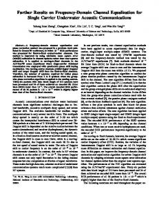
Description of Polynomial Cancellation Coded OFDM system OFDM is the modulation method chosen for many high-speed digital communication systems. This is despite OFDM having a number of well-known disadvantages that include extreme sensitivity to frequency offset, large out-of-band power, and high peak-to-mean power ratio. One of the often-quoted advantages of OFDM is that by using a cyclic prefix it can be made insensitive to multipath transmission. However this is at the cost of some loss in bandwidth efficiency. One technique which has the potential to solve many of the problems of OFDM is Polynomial Cancellation Coding (PCC) [1,2]. In PCC-OFDM the data to be transmitted is mapped onto weighted groups of subcarriers rather than individual subcarriers. High speed Divide into data low bit rate streams
d 0,i M dn−1,i
Mapping of data onto subcarriers
a0,i M aN−1,i
N point Inverse DFT
b0,i M bN−1,i
exp ( j 2π f c t ) Parallel to Serial DAC and filtering
TRANSMITTER
z 0,i dˆ 0,i Weight M and add M dˆ N−1,i sub- zN−1,i carriers
N point DFT
exp (− y0,i Filtering ADC M and yN−1,i Serial to
X
x(t ) h(t )
j 2π f cr t ) X
BPF
+
Parallel
RECEIVER
n(t )
CHANNEL
Figure 1. Block diagram of PCC-OFDM communication system Figure 1 shows the block diagram of a PCC-OFDM communication system. Compared with standard OFDM there is an extra block in the transmitter to map the data onto the subcarriers. There is also an extra block in the receiver marked ‘weight and add subcarriers’. This combines the received subcarriers in a group and can be shown to result in matched filtering of the received signal [3]. The same weightings are used in the transmitter and receiver and these are chosen so that intercarrier interference (ICI) tends to cancel. The results are completely general and any number of subcarriers can be used in a group. In most practical situations groups of only two subcarriers are required. In this case the two subcarriers in a group are given relative weightings +1 and –1. PCC-OFDM has been shown to be much less sensitive to frequency offset and Doppler spread than standard OFDM [1,2]. It has also been shown to have better spectral roll-off and reduced sensitivity to multipath propagation [3].
Spectral Efficiency of PCC-OFDM Despite its many advantages, PCC-OFDM used in its simplest form has one major disadvantage - loss in spectral efficiency. The use of two subcarriers, instead of one, to transmit each complex value, reduces the spectral efficiency by half. The elimination of the cyclic prefix, the improved spectral roll-off and the reduction in ICI will make up for some, but not all, of this loss. Two ways of retaining the benefits of PCC-OFDM, while increasing the spectral efficiency have been explored. These can broadly be described as ‘overlapping in frequency’ and ‘overlapping in time’. It can be shown that ‘overlapping in frequency’ is a form of the well-known technique called partial-response signaling [4]. A number of groups have independently been researching this and similar approaches. However our research has shown that it is not particularly effective. This is because the ‘weighting and adding’ block in the PCC-OFDM receiver contributes significantly to the improved performance [5] and this block can not readily be incorporated into a partial-response system. The second approach, ‘overlapping in time’ in which the symbol periods of adjacent symbols overlap gives much better results. Symbols of duration T are transmitted at intervals of less
1
than T , typically T 2 . In other words intersymbol interference (ISI) is deliberately introduced at the transmitter to increase the data rate. This can be achieved by adding some extra circuitry in the transmitter after the inverse DFT. The rate of clocking of the IDFT must also be increased to the new symbol rate. An equalizer is required in the receiver to recover the transmitted data. This can be either a time domain equalizer or a frequency domain equalizer but as will be shown particularly simple and effective frequency domain equalizers can be designed. The rate of clocking of the receiver DFT must also be increased to the new symbol rate.
Impulse response for ideal channel Frequency domain equalizers are not normally used in OFDM to counteract the effects of multipath transmission. Instead a cyclic prefix is used. This is because the ICI resulting from ISI is spread across a large number of subcarriers and an impractical number of equalizer taps would be required. The polynomial cancellation properties of PCC also work to cancel the interference caused by ISI so that there are only a few significant terms. This means that the equalizer structures can be much simpler. In general the interference is two-dimensional; it is between symbols and also between subcarriers within a symbol. The equalizers, which are being considered for PCC-OFDM, are two dimensional frequency domain equalizers, which operate on the outputs of the ‘weighting and adding’ block. 1.0 0.8 0.6 0.4 0.2 0.0
amplitude
1
S
5
9
S
4
symbol
1
13
subcarrier pair
Figure 2. Amplitude of two dimensional impulse response for ideal channel Figure 2 shows the outputs from the ‘weighting and adding’ block in the receiver, which result from one transmitted subcarrier pair in one symbol. It can be considered as a form of two-dimensional impulse response. Because each symbol overlaps in time only with the preceding and following symbol, the impulse response has non-zero terms only for three symbols: the preceding, the current and the following symbol. In the current symbol, only the wanted subcarrier pair has a non-zero value. In the preceding and following symbols there are three significant terms; these are for the corresponding subcarrier pair and the subcarrier pairs on each side. The total impulse response has only seven terms greater than -20dB, only three of which are above -10dB. In a PCCOFDM system with overlapping in time and an ideal channel the equalizer in the receiver would to have to equalize this response. For a real channel, the equalizer would also have to compensate for the added distortion in the channel. This would change the details of figure 2 but, because of the properties of PCC-OFDM, would still result in an impulse response with only a small number of significant terms.
Frequency Domain Equalizers A number of forms of equalizer have been simulated. In all of the simulations OFDM with 32 subcarriers was used. Each subcarrier pair was modulated with 4QAM. The simulations were for 100 transmitted symbols. Figure 3 shows the scatter diagram before equalization. Figure 3(a) is for the case of no noise, while Figure 3(b) is for the case of additive white Gaussian noise and a SNR of 10dB at the receiver input. 2
2
1.5
1.5
1
1
0.5
0.5
0
0
-0.5
-0.5
-1
-1
-1.5
-1.5
-2 -2
-1.5
-1
-0.5
0
0.5
1
1.5
2
-2 -2
-1.5
-1
-0.5
0
0.5
1
1.5
2
(a) No noise (b) Received SNR=10dB Figure 3. Scatter diagram with no equalization
2
By extending well-known equalizer theory to two dimensions, a linear zero forcing equalizer operating on three symbols was designed. Figure 4 shows the scatter diagrams that resulted. The zero forcing linear equalizer was not very effective in equalizing the signal and also resulted in considerable noise enhancement. 2
2
1.5
1.5
1
1
0.5
0.5
0
0
-0.5
-0.5
-1
-1
-1.5
-1.5
-2 -2
-1.5
-1
-0.5
0
0.5
1
1.5
2
-2 -2
-1.5
-1
-0.5
0
0.5
1
1.5
2
(a) No noise (b) Received SNR=10dB Figure 4. Scatter diagram with zero forcing equalizer operating on three symbols Figure 5 shows the results of simulations of a two-dimensional decision feedback equalizer with two linear feedforward stages. In other words decision feedback was used to subtract out the interference from the preceding symbol, linear equalization was used to reduce the interference from the following two symbols. Figure 5(a) shows the case for no noise. Each of the four constellation point has become a well-defined array of points. This is because of the small number of significant terms in the impulse response. In the simulations correct decisions were assumed. This is a realistic assumption, as although individual subcarrier pairs in a symbol may be decoded incorrectly, error-correcting codes are normally used across a symbol and the overall probability of an uncorrected error is low. Unlike the zero-forcing equalizer, the decision feedback equalizers cause negligible noise enhancement. 2
2
1.5
1.5
1
1
0.5
0.5
0
0
-0.5
-0.5
-1
-1
-1.5
-1.5
-2 -2
-1.5
-1
-0.5
0
0.5
(a) No noise
1
1.5
2
-2 -2
-1.5
-1
-0.5
0
0.5
1
1.5
2
(b) Received SNR=10dB
Figure 5 Decision Feedback equalizer with two stages of linear feedforward equalization
Conclusions PCC-OFDM is a new method of combining coding and modulation to improve the properties of OFDM. By overlapping PCC-OFDM symbols in time, these improvements can be gained while at the same time increasing the overall spectral efficiency of the OFDM system. Equalizers are required in the receiver to recover the transmitted data. In this paper the results of simulations of a PCC-OFDM with frequency domain equalizers have been presented. It has been shown that comparatively simple decision feedback equalizers can cancel the distortion with minimal noise enhancement. Zero forcing linear equalizers have been shown to give very poor results, as they are both ineffective at equalizing the signal and cause considerable noise enhancement.
References 1. 2. 3. 4. 5.
J. Armstrong, “Analysis of new and existing methods of reducing intercarrier interference due to carrier frequency offset in OFDM” IEEE Transactions on Communications, Vol 47, No3, March 1999, pp365-369. J. Armstrong, P.M. Grant, G. Povey, “Polynomial cancellation coding of OFDM to reduce Intercarrier interference due to Doppler spread”, IEEE Globecom , vol 5, pp. 2771-2776, 1998. J. Armstrong, ‘Polynomial Cancellation Coding with Overlapping Symbol Periods’, submitted to IEEE Journal on Selected Areas in Communications. J. Armstrong, P.M. Grant, “Polynomial Cancellation Coding of OFDM with mapping of data onto overlapping groups of subcarriers”, submitted to IEEE Communications Letters. K. Seaton and J. Armstrong, ‘Polynomial Cancellation Coding and finite differences’, submitted to IEEE Transactions on Information Theory.
3