thank the other members of the supervisory committee, Dr. John Ziegert and Dr. ...... Schmitz, T.L., Couey, J., Marsh, E., and Tummond, M.F., 2004, The Role of ...
FREQUENCY DOMAIN PREDICTION OF SURFACE LOCATION ERROR IN MILLING
By RAÚL E. ZAPATA-RAMOS
A THESIS PRESENTED TO THE GRADUATE SCHOOL OF THE UNIVERSITY OF FLORIDA IN PARTIAL FULFILLMENT OF THE REQUIREMENTS FOR THE DEGREE OF MASTERS OF SCIENCE UNIVERSITY OF FLORIDA 2006
Copyright 2006 by Raúl E. Zapata-Ramos
To my family as a whole, for their invaluable support through every moment of frustration
ACKNOWLEDGMENTS I would like to thank my advisor, Dr. Tony L. Schmitz, for his patience, his ideas, and for providing the opportunity to participate in this experience. I would also like to thank the other members of the supervisory committee, Dr. John Ziegert and Dr. Peter Ifju, for their participation. I also extend my gratitude to Chi-Hung Cheng, G. Scott Duncan, Kevin Powell, Suzanne Canning, and Vadim J. Tyamanski, for their assistance in the completion of this research. This work was supported in part by BWXT Y-12, Oak Ridge, TN, and the Naval Surface Warfare Center-Carderock Division, Carderock, MD.
iv
TABLE OF CONTENTS page ACKNOWLEDGMENTS ................................................................................................. iv LIST OF TABLES............................................................................................................. vi LIST OF FIGURES .......................................................................................................... vii ABSTRACT....................................................................................................................... ix CHAPTER 1
INTRODUCTION ........................................................................................................1
2
LITERATURE REVIEW .............................................................................................7
3
FREQUENCY DOMAIN SOLUTION......................................................................10 Cutting Force Model...................................................................................................12 Implementation ...........................................................................................................17
4
NUMERICAL AND EXPERIMENTAL VERIFICATION ......................................24 Numerical Comparison of Time Domain Simulation to Frequency Domain Solution for surface location error ..........................................................................24 Comparison of Analytical Frequency Domain Solution to an Experimental Single Degree of Freedom System.....................................................................................29 Comparison of Analytical Frequency Domain Solution to Two Degree of Freedom Setup ........................................................................................................38 Comparison of Analytical Frequency Domain Solution to a Complex Multiple Degree of Freedom System.....................................................................................43
5
CONCLUSIONS ........................................................................................................52 Completed Work.........................................................................................................52 Future Work................................................................................................................56
LIST OF REFERENCES...................................................................................................58 BIOGRAPHICAL SKETCH .............................................................................................61
v
LIST OF TABLES page
Table 3.1
Parameters for surface roughness and surface profile figures..................................21
4.1
Spindle speed and feed rates for the cutting tests.....................................................34
4.2
Spindle speeds and feed rates used in the two degree of freedom test.....................41
4.3
Spindle speed and feed rate values for the first 54 multiple degree of freedom test cuts.....................................................................................................................49
4.4
Spindle speed and feed rate values for the last 54 multiple degree of freedom test cuts. ..........................................................................................................................49
vi
LIST OF FIGURES page
Figure 1.1
Stability lobe diagram for Single Degree of freedom test..........................................4
3.1
Example of undercutting SLE. .................................................................................11
3.2
Schematic of the forces angle and coordinate system used......................................13
3.3
Diagram of the three dimensional array for the Fourier series data.........................18
3.4
Force comparison using Eq. 3.3 and the Fourier series approximation for 5, 20, and 100 terms. ..........................................................................................................19
3.5
Surface profile of a 0.5 mm deep cut. ......................................................................21
3.6
Schematic of the tool system as viewed in the next two figures..............................22
3.7
SLE for an axial depth of 0.5 mm. ...........................................................................22
3.8
SLE for an axial depth of a 25 mm. .........................................................................23
4.1
Stability lobes for the simulated system...................................................................25
4.2
Up milling cutting force, single tooth engagement at low radial immersion. ..........26
4.3
Down milling cutting force, same conditions and labels as Figure 4.2. ..................27
4.4
Comparison between time domain simulation results and frequency domain solution results..........................................................................................................28
4.5
SLE test part. ............................................................................................................30
4.6
Single degree of freedom test setup. ........................................................................31
4.7
Pretest FRF for the single degree of freedom setup. ................................................32
4.8
Stability lobes for the single degree of freedom FRF presented in Figure 4.7.........33
4.9
Analytical SLE profile for the single degree of freedom system. ............................33
4.10 Relative measurement positions along the cross-section of one of the cut bosses. .35
vii
4.11 Comparison of the predicted and experimental SLE values. ...................................35 4.12 Comparison of the accelerometer (top) and the laser vibrometer (bottom) measurements. ..........................................................................................................37 4.13 Comparison of the predicted and experimental velocity data. .................................37 4.14 Photograph of the two degree of freedom setup. .....................................................39 4.15 FRF for the two degree of freedom system..............................................................40 4.16 Stability diagram for the two degree of freedom system. ........................................40 4.17 SLE predictions for the two degree of freedom system using a 6 mm axial depth and 1 mm radial depth..............................................................................................41 4.18 Comparison of experiment and prediction for the two degree of freedom flexural system.......................................................................................................................42 4.19 Comparison of experimental and predicted velocity data at 6500 rpm....................43 4.20 Multiple degree of freedom test part. .......................................................................44 4.21 Tool point FRF for the 19.05 mm diameter endmill mounted in a large collet holder........................................................................................................................45 4.20 Stability lobe diagram for multiple degree of freedom setup...................................46 4.21 SLE predictions for the multiple degree of freedom setup. .....................................46 4.22 Schematic of the cutting test tool path. ....................................................................47 4.23 Comparison of predicted and experimental SLE data for the multiple degree of freedom setup. ..........................................................................................................50 4.24 Comparison of the FRF’s of the carbide rod at various spindle speeds...................51
viii
Abstract of Thesis Presented to the Graduate School of the University of Florida in Partial Fulfillment of the Requirements for the Degree of Master of Science FREQUENCY DOMAIN PREDICTION OF SURFACE LOCATION ERROR IN MILLING By Raúl E. Zapata-Ramos August 2006 Chair: Tony L. Schmitz Major Department: Mechanical and Aerospace Engineering Computer numerically-controlled (CNC) machine tools are essential in modern-day manufacturing facilities. Many of the problems inherent to early machine tools, such as machine geometric errors, thermal errors, and dynamic positioning errors, have been greatly reduced due to extensive research in these areas. As a result, modern-day CNC machine tools are highly accurate instruments. However, with the advent of high-speed machining (HSM), additional errors due to process dynamics have become problematic. One of the errors introduced by milling process dynamics is surface location error (SLE). Surface location error refers to a difference between the actual and commanded locations of the machined surface. This discrepancy in the final position of the surface is caused by the steady state vibrations of the tool as it removes the material. In milling, the final surface location is determined by the position of the cutting edge when it enters (up milling) or exits (down milling) the cut. During the steady state portion of a stable cut,
ix
this position is, by definition, repeatable and predictable. As a result, recent research has led to methods of predicting SLE analytically. This research provides a verification of a frequency domain approach to predict SLE. Predictions from the frequency domain approach are compared to results from time domain simulation of the milling process and data from three experimental setups. The comparison to time domain simulation provides insight into the strengths and weaknesses of the method. The first and second experimental setups (single and two degree of freedom tests) use flexures to control the system dynamics and reproduce situations in which the workpiece is the most flexible part of the system. The third experimental setup provides a multiple degree of freedom test and does not use any flexures to control the system dynamics. In this case, the tool-holder-spindle system is the most flexible part of the setup. This final comparison provides a more complex dynamic system and is used to evaluate the robustness of the new prediction method.
x
CHAPTER 1 INTRODUCTION Computer numerically-controlled (CNC) machining began in the late 1940s and throughout the 1950s. The first system for automated positioning of the cutting tool was developed by the Parsons Corporation in 1947. The addition of computers to the system in 1952 was completed at the Massachusetts Institute of Technology. Finally, the first production CNC machines were introduced in 1957 [1–2]. CNC machining dramatically reduces the time and errors involved in production machining and allows complex manual procedures, such as machining curves, to be decomposed into manageable subroutines. Part preprogramming also removes many possibilities for human error and enables the machinist to perform other tasks during program execution, increasing machine shop efficiency. Since 1957, most machine shops have added CNC capabilities because of the added productivity and flexibility this process provides. However, even though the machine controls the nominal motions, this does not guarantee accurate parts. Error sources which must be considered include thermal errors, geometric errors, controller errors, and process errors. Thermal errors are problematic because, as temperature increases, different parts of the machine expand at different rates. This causes distortions of the machine structure and dimensional inaccuracies in the finished product. Thermal errors can be divided into two categories. The first of these is a temperature increase in the machine structure due to atmospheric temperature changes, outside heat sources, or machine operation. Analysis is
1
2 complicated by the multiple heat inputs. The spindle heats as it rotates at a rate that depends on the spindle speed. The machine axes and the devices used to measure motions also exhibit temperature increases. Accurate operation of the machine requires strategies for monitoring and controlling the heat introduced from these various sources. In the past decades, researchers and production companies have implemented different solutions to this problem. Some choose to isolate their machines in temperature-controlled environments. Others make their machines, or parts of their machines, out of materials that are less sensitive to temperature fluctuations. Most spindle manufacturers now provide cooling systems for their spindles. The second thermal error source is heat input from friction in the cutting process. This second category is easier to eliminate than the first. Coolant can be sprayed or washed over the workpiece to remove heat during machining, thereby maintaining a constant temperature. However, this requires temperature control of the coolant as well. In recent years, tool coatings for endmills and other cutting tools have been used to reduce friction and reactivity between the tool and the workpiece, which reduces the heat input to the system from friction and tool degradation. Tool path errors also have two separate sources. The first is errors in the machine geometry, while the second is errors related to the CNC controller algorithm and gains. Machine geometric errors refer to the quasi-static accuracy of the machine positioning capability, which is directly dependent on the precision with which the guideways are manufactured and assembled. Most machine geometries include offsets between the position transducers and the tool/workpiece location. These offsets, usually called Abbe offsets in error analysis [3], exacerbate the inherent geometric errors to levels which are
3 not permissible in modern day precision machining. Perpendicularity of the axes is also monitored and errors of a few arc seconds are present in general [4]. Although these errors are always present, compensation is possible. Using devices such as the laser ball bar [5–6], the geometric errors of the assembled machine can be measured and then compensated mathematically using homogeneous transformation matrix (HTM) [4] representations of the machine geometry to prescribe the corrective motions of the machine axes. Controller errors are different from the previous error source because they are only present when the machine is moving from one position to another. Closed-loop controller algorithms function use the error signal generated from a difference between the commanded and current positions to drive the individual axes and position the tool point along the commanded contour. Mismatched gains between the drives leads to path errors. Transients during cornering motions can also lead to degraded part accuracy. Prior to the introduction of high speed machining (HSM), these three error sources (thermal expansion, machine geometry, and controller errors) were the largest contributors to machining errors. Therefore, significant research was carried out to minimize them. As a result, these three error sources are typically small in modern day machine tools. However, process effects are more challenging to address in turnkey installations. Chatter, for example, remains a problem in production environments. Prior to research performed by Tobias, Arnold, Tlusty, and Merrit [7–13], the primary mechanisms that cause chatter, or unstable cutting conditions, remained a mystery. Their research provided methods of predicting chatter and led to the development of stability
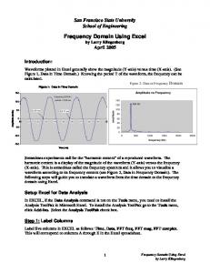
4 lobe diagrams. These diagrams require knowledge of the system dynamics (as depicted in the system’s frequency response function or FRF) and the cutting conditions (radial cutting depth, number of teeth on the cutter, and cutting force coefficients). These diagrams depict areas of stable cutting with respect to spindle speed and axial depth of cut. Furthermore, they showed that more efficient cutting was possible by machining at higher spindle speeds, i.e., high speed machining. Figure 1.1 is an example of a stability lobe diagram used in this study.
Figure 1.1: Stability lobe diagram for Single Degree of freedom test. Note that as spindle speed increases the space between the lobes grows in width and height. During high speed machining, the cutting teeth are impact the workpiece much faster and at more aggressive feed rates than the previous standard for metal cutting. Higher feed rates result in higher forces. Larger cutting forces translate to increased vibrations amplitudes of the cutting tool, particularly near resonances of the structural dynamics. This, in turn, leads to larger errors due to these forced vibrations (a previously negligible error source at lower forcing frequencies). High speed machining is becoming
5 increasingly popular in modern day machine shops. As a result, modeling these vibrations has become an important area of study. Prior models of the machining processes dynamics showed that the steady state relationship between the cutting forces and resulting vibrations was responsible for determining the final location of the cut surface [14]. The difference between this final location and the commanded location of the surface is known as surface location error (SLE). SLE, like chatter, is dependent on the system FRF. The FRF shows the complexvalued relationship, i.e., both magnitude and phase, between the input and output of the system. A typical goal of high speed machining is to find combinations of machining parameters that enable high material removal rates and reduced machining time. Stability diagrams [7–13, 15–17] identify stable spindle speeds with high axial depths of cut. These areas coincide with the natural frequencies in the FRF. Therefore, these areas also produce the largest vibrations and have the largest sensitivity to phase along the spindle speed vector. This translates to large sensitivity of SLE to spindle speed and changes in the system dynamics. For example, two nominally identical systems (same machine, spindle, holder, and tool models) may produce notably different SLE behavior because their FRF’s are different. Even changing the tool overhang length slightly can change the FRF and SLE. Identifying and verifying a model that can predict these changes is an important activity. This research focuses on verifying a SLE model proposed in reference [18]. This model uses the system FRF directly to model the changes in SLE, in the same way as stability lobe diagrams use the FRF to predict chatter. The FRF-based approach uses cutting coefficients to determine cutting forces for a specific cut. Then, the model
6 predicts displacements by multiplying the cutting force by the FRF (in the frequency domain). Inverse Fourier transforming this product and sampling this data at the appropriate intervals provides the SLE data. In this research, this method is compared to time domain simulation and data from three experimental setups to determine its strengths and weaknesses.
CHAPTER 2 LITERATURE REVIEW This literature review summarizes prior surface location error (SLE) research. These investigations include both model descriptions and experimental results. Studies of SLE have become increasingly common with the widespread application of high-speed machining in various production environments. It is generally understood that this problem arises from the tool/workpiece vibrations during stable machining. One previous study approached the problem by analytically determining the “average locations” of the vibrations to identify the surface left by the cutting tool [19]. Numerous locations were calculated and equated to a particular axial depth and helix angle combination. These locations were then used to construct a surface profile of the cut. In this work, SLE was calculated using a static, rather than dynamic, approach and spindle speed effects were not considered. Other studies have analyzed SLE as a dynamic problem. In 1982, Kline et al. [20] used a previously developed cutting force model and combined it with models for cutter and workpiece deflections to predict the surface profile of the part. In this paper, the cutting condition, geometry, and material properties were used to obtain a more accurate model of the cutting system. The results from prediction were compared to experiment. A 5% to 15% difference between the model and experiment was observed, depending on model parameters. In the same year, Kline et al. [21] provided a new cutting force model based on the chip load, the cut geometry, and the relationship between cutting forces and chip load. This model was also used to explore SLE.
7
8 In 1986, Sutherland and DeVor [22] created a new cutting force model that included feedback mechanisms to optimize the chip thickness and tool deflection data to provide a more accurate picture of the cutting forces. This work included a more accurate description of the milled surface than previous efforts that approximated the tool as a rigid structure. In 1991 and 1992, Altintas and Montgomery [23–24] performed further investigation of this area. They studied situations in which the workpiece was flexible and the effects of this flexibility on the machined part dimensions. In 1999, Schmitz and Ziegert [14] examined SLE as an effect of the phasing of cutter vibrations. In this research, the vibrations and angular position of the tool were combined to form the full cutting profile. This was then compared to the desired surface location to obtain the error. In this study, results from time domain simulation were compared to experimental data for a multiple degree of freedom test setup. In 2003, this analysis was extended using tool rotation and helix angle to determine SLE along the full axial depth of the tool [25]. Time domain simulation was again applied to predict their results. Tlusty [3] also provided a description of SLE and its relationship to tool vibrations. Profile errors due to rotating helical tools are described. Mann et al. [26–27] provided a new approach to modeling SLE. This new approach, referred to as time finite element analysis (TFEA), was reported to be much faster than time domain simulation. TFEA is a variant of finite element analysis where time is segmented, as opposed to space, to calculate the milling process behavior including SLE, stability, and nonlinear effects. However, TFEA still suffers from a weakness shared with time domain simulation. The system’s vibration characteristics, as represented in the frequency response function (FRF), must be approximated using modal
9 parameters. This means that the FRF of the system cannot be used directly in the algorithm. The required modal fit is not a trivial exercise in many instances, which makes the method less attractive to many machine shops where trained engineers may not be available to complete the necessary fit. In 2005, Budak presented an analytical model of the milling cutting forces and used the model to complete form error analyses on numerous milling tool configurations with promising results [28]. In this method, the cutting tool was modeled in segments using nominal material parameters and beam theory. The rest of the system was modeled using modal parameters. The results showed reasonable agreement between experimental and simulated results. This approach has not been compared to other methods in terms of computational efficiency. Also in 2005, Schmitz and Mann [29] provided two analytical methods for predicting SLE. The harmonic balance approach was presented, but still required the use of modal parameters to describe the system dynamics. The new frequency domain approach, on the other hand, enabled the use of the system FRF directly. The FRF could be determined from experimental testing or prediction methods, such as receptance coupling substructure analysis [30–32]. This provided an added flexibility not present in other methods that is desirable in machine shop environments. The results from both methods were compared to single degree of freedom cutting tests and showed reasonable agreement. The frequency domain prediction approach is the method studied in this research.
CHAPTER 3 FREQUENCY DOMAIN SOLUTION Studies of machining dynamics began decades ago with research in the area of machining stability. Early work by Tobias, Arnold, Tlusty, and Merrit identified “regeneration of waviness” on the cut surface as a primary mechanism for the growth of self-excited vibrations in machining [7–13, 15–18]. Regeneration of waviness in milling describes the process by which one tooth overcuts the surface left by the previous tooth causing the modulation of instantaneous chip thickness and cutting forces. These variations affect subsequent tool vibrations which can cascade into unstable cutting conditions. These and further studies led to the use of the cutting system’s dynamic response, as represented by the frequency response function (FRF), to create frequency domain solutions for milling stability [15–16]. This information is presented in the form of stability lobe diagrams that use spindle speed and axial depth of cut as variables to identify stable and unstable cutting zones. The other process parameters, such as feed per tooth, cutting coefficients, and radial immersion are held constant in each diagram. A frequency domain surface location error solution complements these frequency domain stability diagrams and provides a clearer picture of the effect of the system dynamics on the overall milling process. Milling is, by definition, an interrupted cutting process in which the teeth on the cutting tool repeatedly impact the part and cut away small chips from the material. Therefore, even under stable cutting conditions, the tool experiences periodic forced vibrations. The magnitude and phase of these vibrations depend on the process
10
11 parameters, such as the dynamic response of the system (represented by the FRF), the excitation frequency (which depends on the spindle speed and the number of teeth on the cutter), the cutting coefficients of the tool/workpiece system, the radial and axial depths of cut, the feed per tooth, and the cutter helix angle. The location of the individual teeth as they enter (up milling) or exit (down milling) the cut as the tool vibrates determines the final location of the machined surface. Depending on the excitation frequency and its relationship to the system natural frequencies, the tool may remove less material than commanded (undercutting) or more material than commanded (overcutting). Figure 3.1 shows an example of undercutting. These errors are called surface location errors (SLE).
Actual Commanded
y x
Figure 3.1: Example of undercutting surface location error. The frequency domain solution for surface location error requires two assumptions. First, the influence of regeneration is neglected because the machining process is stable and governed by steady state vibrations. Second, although tool vibrations occur in both the x- and y-directions (Figure 3.1), y-direction vibrations dominate the surface location (for x-direction feed). Given these conditions, the solution method can be divided into three steps: 1.
Express the y-direction cutting force, Fy (ω ) in the frequency domain.
2.
Determine the y-direction displacement, Y (ω ) , in the frequency domain by multiplying the y-direction cutting force by the y-direction FRF. Y (ω ) Fy (ω ) Y (ω ) = Fy (ω )
12 3.
Inverse Fourier transform the resulting displacement data and sample at the cut entrance or exit to determine surface location error. This approach provides the added convenience of allowing the use of either a
measured or a predicted FRF [18] without the need for a modal fit. This differs from time domain simulation, which requires modal parameters to evaluate the differential equations that describe the cutting process. Also, unlike time domain simulation, the force data used in this frequency domain approach do not use a feedback mechanism to adjust instantaneous chip thickness (no regeneration). Therefore stable cutting conditions must be ensured separately. Cutting Force Model
There are several cutting force models available. The form shown in Eq. 3.1 has been applied here [29]. This model relates the tangential, Ft , and normal, Fn , cutting force components to the chip width or axial depth of cut, b , and chip thickness, h , and allows Fy to be expressed as shown in Eq. 3.2. Figure 3.2 shows a diagram of the forces and angles involved in this force model.
Ft (φ ) = k t bh(φ ) + k te b
(3.1)
Fn (φ ) = k n bh(φ ) + k ne b − knc N ⎡ − kt c N ( )( ) − + g φ 1 cos 2 φ ∑ ∑ g (φi )sin 2φi i i ⎢ 2 2 i =1 i =1 Fy (φ ) = −b ⎢ N ⎢ ⎢k te ∑ g (φi )sin φ i − k ne ∑ g (φ i ) cos φi ⎣ i =1
⎤ −⎥ ⎥ ⎥ ⎥ ⎦
(3.2)
13 y
φ x ٛٛ
ٛ
Fn
ٛ
Ft
Figure 3.2: Forces, angle and coordinate system used. The summations in Eq. 3.2 account for all of the teeth on the cutter and their current positions. In theses equations, k t , k n , k te , and k ne represent the cutting coefficients, g is a switching function set to one when the ith tooth (N teeth total) is cutting and zero when it is not, and c is the feed per tooth. Also, φi is the angle of the current tooth, which for evenly spaced teeth can be described as φi = ωt +
2π (i − 1) , N
where ω is the spindle speed in rad/s. Equation 3.2 does not account for the helix angle,
β , of the tools. In order to model the helix angle, a common method is to divide the tool into multiple slices along its axis ( A total slices are used here). Each of these slices is modeled as a straight tooth cutter; however, each one is rotated around the tool axis by the angle ψ =
db ⋅ 2 tan β , where db is the height of each axial slice and d is the tool d
diameter. Each of these slices is then evaluated individually. This is accomplished by adding another summation (Eq. 3.3) and changing the formula for φi to
φ i = ωt +
2π (i − 1) − ψ ( j − 1) , where j is the number identifying the current axial slice. N
In the case of unevenly spaced teeth the only change required is to replace appropriate angular locations of the teeth.
2π with the N
14
− knc N ⎡ − kt c N ( )( ) − + g φ 1 cos 2 φ ∑ ∑ g (φi )sin 2φi i i A ⎢ 2 2 i =1 i =1 Fy (φ ) = −b∑ ⎢ N j =1 ⎢ ⎢k te ∑ g (φ i )sin φi − k ne ∑ g (φ i ) cos φ i ⎣ i =1
⎤ −⎥ ⎥ ⎥ ⎥ ⎦
(3.3)
At this point two options are available for proceeding with the solution method. Equation 3.3 can be directly evaluated for one revolution of the tool ( φ is a function of time so Eq. 3.3 has to be evaluated at discrete intervals during the rotation) or it can be represented by a Fourier series [29]. In either case, the result is a vector of force data for one revolution of the tool. Only one revolution of the tool is necessary because the process is in steady state and stable. Therefore, the force resulting from the engagement of the teeth during each revolution should be nominally identical to the next. The direct evaluation of Eq. 3.3 is trivial and will not be explained further here. The Fourier series is described in more detail. An equivalent Fourier series representation of Eq. 3.3 can be written as A N ∞ ⎛ ⎞ Fy (φ ) = ∑∑ ⎜ a 0 + ∑ (a n cos nφi + bn sin nφi )⎟ j =1 i =1 ⎝ n =1 ⎠
(3.4).
where the coefficients of the series, ao , a n , and bn , must be evaluated. Each coefficient is described by a separate integral which spans over one cutter rotation as shown in Eq. 3.5. The integrals can be divided into three separate ranges bounded by 0 , φ1 , π , and 2π , where φ1 is either the entry angle of the cut (down milling) or the exit angle of the cut (up milling). Equation 3.6 shows the separation of the integral over the relevant ranges using the a0 equation.
15
2π
∫ F (φ )dφ
1 ao = 2π an = bn =
ao =
1 2π
1
π 1
π
y
0
2π
∫ F (φ )cos nφdφ
(3.5)
y
0
2π
∫ F (φ )sin nφdφ y
0
π 2π ⎡φ1 ⎤ ⎢ ∫ Fy (φ )dφ + ∫ Fy (φ )dφ + ∫ Fy (φ )dφ ⎥ ⎢⎣ 0 ⎥⎦ φ1 π
(3.6)
The portion of the integrals evaluated from π to 2π is always zero (using the circular tool path approximation), while the other two portions have the possibility of being nonzero. An up milling cutting condition would cause the first part of the integral to be nonzero and the second to be zero, whereas a down milling condition provides the opposite case. The experimental testing and numerical simulations provided in the rest of the study are for down milling due to the generally improved surface finish, which makes it the preferred choice for finishing passes. Therefore, ao is evaluated for down milling in Eq. 3.7 as an example. bN a0 = − 2π
π
knc ⎡ k t cφ k t c ⎤ ⎢− 2 + 4 sin 2φ − 4 cos 2φ + k te cos φ + k ne sin φ ⎥ ⎣ ⎦ φ1
(3.7)
The a n and bn coefficients are evaluated in a similar manner. Additionally, closed form expressions can be used to evaluate these coefficients by observing the pattern that emerges once n > 2 , as shown in Eqs. 3.8–3.13.
16 π
⎡ ⎛ 1 1 1 ⎞ ⎤ ⎛ 1 ⎞ ⎢kt c⎜ − 4 sin 2φ + 12 sin 3φ ⎟ + k n c⎜ − 4 cos φ − 12 cos 3φ ⎟ + ⎥ bN ⎢ ⎝ ⎝ ⎠ ⎥ ⎠ a1 = − π ⎢ ⎛1 ⎥ 1 ⎛1 ⎞ ⎞ ⎥ ⎢kte ⎜ cos 2φ ⎟ + k ne ⎜ φ + sin 2φ ⎟ 4 ⎝2 ⎠ ⎠ ⎦φ1 ⎣ ⎝4
(3.8)
π
⎡ ⎛1 1 1 ⎞ ⎛ 1 ⎞ ⎤ ⎢kt c⎜ 4 φ − 4 sin 2φ + 16 sin 4φ ⎟ + k n c⎜ − 16 cos 4φ ⎟ + ⎥ bN ⎢ ⎝ ⎠ ⎝ ⎠ ⎥ a2 = − π ⎢ ⎛ 1 1 1 ⎞ ⎛1 ⎞ ⎥ ⎢kte ⎜ − cos φ + cos 3φ ⎟ + k ne ⎜ sin φ + sin 3φ ⎟ ⎥ 6 6 ⎠ ⎝2 ⎠ ⎦φ1 ⎣ ⎝ 2
(3.9)
π
⎡ ⎛ 1 ⎞ ⎤ 1 1 sin (n + 2 )φ ⎟⎟ + ⎥ sin (n − 2 )φ + ⎢k t c⎜⎜ − sin nφ + 4(n + 2 ) 4(n − 2 ) ⎠ ⎥ ⎢ ⎝ 2n ⎢ ⎛ ⎥ ⎞ 1 1 ⎢k n c⎜⎜ − ⎥ cos(n − 2 )φ − cos(n + 2 )φ ⎟⎟ + 4(n + 2 ) ⎥ bN ⎢ ⎝ 4(n − 2 ) ⎠ (3.10) an = − ⎢ ⎥ n = 3,4,... π ⎢ ⎛ ⎞ 1 1 ⎥ k ⎜− cos(n − 1)φ + cos(n + 1)φ ⎟⎟ + ⎢ te ⎜⎝ 2(n − 1) ⎥ 2(n + 1) ⎠ ⎢ ⎥ ⎞ 1 1 ⎢ ⎛ ⎥ ⎢k ne ⎜⎜ − 2(n − 1) sin (n − 1)φ + 2(n + 1) sin (n + 1)φ ⎟⎟ ⎥ ⎠ ⎣ ⎝ ⎦φ 1
π
⎡ ⎛ 3 1 1 ⎞ ⎛ 1 ⎞ ⎤ ⎢k t c⎜ − 4 cos φ + 12 cos 3φ ⎟ + k n c⎜ − 4 sin φ − 12 sin 3φ ⎟ + ⎥ bN ⎢ ⎝ ⎠ ⎝ ⎠ ⎥ b1 = − ⎥ π ⎢ ⎛ 1 1 ⎞ ⎛ 1 ⎞ ⎢k te ⎜ − φ + sin 2φ ⎟ + k ne ⎜ − cos 2φ ⎟ ⎥ 4 ⎠ ⎝ 4 ⎠ ⎣ ⎝ 2 ⎦ φ1
(3.11)
π
⎡ ⎛1 1 1 ⎞ ⎛1 ⎞ ⎤ ⎢k t c⎜ 4 cos 2φ + 16 cos 4φ ⎟ + k n c⎜ 4 φ − 16 sin 4φ ⎟ + ⎥ bN ⎢ ⎝ ⎠ ⎝ ⎠ ⎥ b2 = − π ⎢ ⎛ 1 1 1 ⎞ ⎛ 1 ⎞⎥ ⎢k te ⎜ − sin φ + sin 3φ ⎟ + k ne ⎜ − cos φ − cos 3φ ⎟⎥ 6 6 ⎠ ⎝ 2 ⎠⎦ φ1 ⎣ ⎝ 2
(3.12)
17 π
⎡ ⎛ 1 ⎞ ⎤ 1 1 cos(n − 2 )φ − cos(n + 2 )φ ⎟⎟ + ⎥ ⎢k t c⎜⎜ cos nφ − 4(n − 2 ) 4(n + 2 ) ⎠ ⎥ ⎢ ⎝ 2n ⎢ ⎛ 1 ⎥ ⎞ 1 ⎢k n c⎜⎜ ⎥ sin (n − 2 )φ − sin (n + 2 )φ ⎟⎟ + 4(n + 2 ) ⎥ bN ⎢ ⎝ 4(n − 2 ) ⎠ (3.13) bn = − ⎢ ⎥ n = 3,4,... π ⎢ ⎛ ⎞ 1 1 ⎥ k ⎜− sin (n − 1)φ + sin (n + 1)φ ⎟⎟ + ⎢ te ⎜⎝ 2(n − 1) ⎥ 2(n + 1) ⎠ ⎢ ⎥ ⎞ 1 1 ⎢ ⎛ ⎥ ⎢k ne ⎜⎜ − 2(n − 1) cos(n − 1)φ − 2(n + 1) cos(n + 1)φ ⎟⎟ ⎥ ⎠ ⎣ ⎝ ⎦φ 1
Once the Fourier series or the direct evaluation of Eq. 3.3 has been completed, the resulting force vector must be transformed to the frequency domain so that it can be multiplied by the FRF to obtain tool vibration data. Finally, SLE is determined from the tool vibration data (inverse Fourier transformed into the time domain) by sampling it at the times when the teeth enter (up milling) or exit (down milling) the cut. Implementation
Implementing the time domain evaluation of Eq. 3.3 is straight forward; input the required parameters and run through a series of loops (time, teeth, and axial slices) where the forces on all the teeth and the axial slices are summed at each instant in time, i.e., every tool rotation angle, to obtain the force time series vector. The main problem facing the implementation of the Fourier series approach is organizing all the data obtained from the evaluation of Eq. 3.4, where each individual tooth on each slice has a different force contribution at each tool angle. A convenient organization method is to create a three dimensional array of the data where each column represents a tooth on the tool, each row represents an axial slice of the tool, and the third dimension represents the separate tool angles or time (Figure 3.3). In order to create the required force vector, the rows and columns at each instant in time are summed to a single value.
18
Axial Section
Time Tooth # Figure 3.3: Three dimensional array for the Fourier series data. Using the Fourier series as a method to approximate the force input offers both advantages and disadvantages. One of the advantages is that by truncating the series to a pre-selected number of terms, computation time can be reduced. In this case high frequency content may be lost, but this content is considered negligible because the displacement at these frequencies is minute in most cases. However, if too few terms are included, the force representation becomes inaccurate causing erroneous results. Also, the number of terms required to accurately represent the data varies depending on the radial immersion of the cut and number of teeth on the cutter. Usually, lower radial immersion cuts require more terms as do a larger number of teeth. However, provided these trends are observed, the inclusion of additional terms in the series results in little, if any, changes in the surface location error results. A comparison of the direct evaluation of Eq. 3.3 and results from the Fourier series approximation with too few (5), just enough (20) and more than enough terms (100) in the series is shown in Figure 3.4.
19
Figure 3.4: Force comparison using Eq. 3.3 and the Fourier series approximation for 5, 20, and 100 terms. Note that at 100 terms the series is almost indistinguishable from Eq. 3.3. There is one aspect of the discrete Fourier transform which must be considered. Prior to performing an inverse Fourier transform on the displacement data (obtained by multiplying the system’s FRF by the force vector), it is necessary to extract the mean or DC component of the displacement data. If not, the discrete inverse Fourier transform algorithm doubles that DC quantity causing overprediction of the surface location error for the machining process. The DC component of the displacement data must be reintroduced after the inverse transform has been performed. Once this step is complete, all the displacement is sampled at the appropriate time intervals to determine the surface location error. In addition to SLE data, there is more information that can be extracted from the algorithm. By combining the angular location of the teeth with feed rate data and tool center vibration data (both the x- and y-direction vibrations are required) it is possible to
20 describe surface finish left by the cycloidal tool path at any axial depth (z). Equation 3.14 describes the full tool path (both x- and y-directions). x feed (t ) = N ⋅ c ⋅ ω ⋅ t
d cos(φ ( z , t )) 2 x full ( z , t ) = x feed (t ) + x angle (z , t ) + x vibrations ( z , t ) x angle ( z , t ) =
(3.14)
d sin (φ ( z , t )) 2 y full ( z , t ) = y angle ( z , t ) + y vibrations (z , t ) y angle ( z , t ) =
Using this information it is possible to compute the surface roughness statistics. The surface roughness is obtained by removing the parts of the tool path that do not define the final surface, leaving only the points that lie on the machined surface. From this data, the cusps left by the machining process can be isolated. Also, by observing this data for each slice simultaneously, the form error caused by the helix angle of the tool also becomes visible. See Figure 3.5 for an example. These results include the contributions of process dynamics in addition to the mechanistic tool path. Cuts performed at low axial depths may appear to have a linear contour in the axial direction (due to helix effects). However, deeper cuts might start to show parabolic or even S-shaped curves depending on the helix angle. Figure 3.6 presents a schematic of the tool and the coordinate system used in these examples. Figures 3.7 and 3.8 show the effects of the helix angle on the same system for axial depths of 0.5 mm and 25 mm. The remaining parameters (see Table 3.1) for the cuts are identical. This data can also be extracted from time domain simulations, but requires increased computation time.
21
Surface Height(µm)
2.5 2 1.5 1 0.5 0 0.4 0.2
Axial Depth (mm)
0 0.2
0.3
0.4
0.5
0.6
Feed (mm)
Figure 3.5: Surface profile of a 0.5 mm deep cut. Cut parameters are given in Table 3.1. Note the cusps and the inclined surface. Table 3.1: Parameters for surface roughness and surface profile figures.
Number of teeth Tool diameter Helix angle Modal stiffness Natural frequency Damping ratio Radial immersion Feed per tooth Tangential cutting coefficient Normal cutting coefficient Tangential edge effects coefficient Normal edge effects coefficient
Quantity 2 0.0127 30 1.00x10⁷ 500 0.1 25%
Units teeth m degrees N/m Hz -
2.0x10⁻⁴ 7.0x10⁸ 2.1x10⁸ 2.0x10³ 2.0x10³
m/tooth N/m2 N/m2 N/m N/m
22
Z
0 Figure 3.6: Tool system as viewed in the next two figures. The tip of the tool is marked as the origin of the axial (z) direction.
Surface Location (µm)
3.8 3.6 3.4 3.2 3 2.8 2.6 2.4 0
0.1
0.2
0.3
0.4
0.5
Axial Depth (mm) Figure 3.7: Surface location error for an axial depth of 0.5 mm. An axial depth of zero denotes the tip of the tool on the graph; the trend appears to be almost a straight line.
23
Surface Location (µm)
180 160 140 120 100 80 60 40 20 0
5
10
15
20
25
Axial Depth (mm) Figure 3.8: Surface location error for an axial depth of a 25 mm. The effect of the helix angle creates an S-shaped curve. The error at the tip of the tool is about 190 mm while it is zero at the top of the cut.
CHAPTER 4 NUMERICAL AND EXPERIMENTAL VERIFICATION Numerical and experimental verifications of the frequency domain surface location error (SLE) solution are provided in this chapter. The numerical comparison is completed using a time domain milling simulation which includes the effects of regeneration, helix angle, and runout [33]. Experimental comparison is realized using three different setups:
•
Single degree of freedom flexure – the flexible direction of the flexure is set in the ydirection of the cut, i.e., perpendicular to the feed direction.
•
Two degree of freedom flexure – two flexures are mounted on top of one another and both have the flexible direction set to the y-direction.
•
Flexible tool – a stiff workpiece is machined using a flexible tool. In this test, the flexibility is approximately equal in both the x- and y-directions. The first two experiments represent situations where the workpiece is the most
flexible part of the cutting system (e.g., machining of thin-walled parts). These setups also provide controllable and repeatable dynamics. The last experiment provides insight into machining with flexible tools such as machining deep pockets with long, slender tools. It also checks the assumption that the y-direction flexibility dominates SLE effects. Numerical Comparison of Time Domain Simulation to Frequency Domain Solution for surface location error
The parameters used in the numerical comparisons are summarized here. The cutting coefficients were k t = 700 N/mm2 , k n = 210 N/mm2, and k te = k ne = 2 N/mm (typical for aluminum). A 19.05 mm diameter, four-flute endmill with a helix angle of 30 deg was selected. A two degree of freedom dynamic system response was created from the following modal parameters: k1 = 5000 N/mm, k 2 = 7000 N/mm, ζ 1 = ζ 2 = 0.05 , 24
25
ω n1 = 800 Hz, and ω n 2 = 900 Hz, where the x- and y-direction parameters were identical. The feed per tooth was set to 0.15 mm per tooth, down milling conditions were selected, and the radial immersion was set to 14.6% or a 45 deg difference between entrance and exit angles. The axial depth of cut was chosen so that a wide, chatter-free spindle speed range could be tested. Using the stability lobe diagram [16] in Figure 4.1, calculated using the previously defined system parameters, a depth of b = 3 mm was selected. 7 6
blim (mm)
5 4 3 2 1 0 0.5
0.65
0.8
0.95
1.1
1.25
1.4
1.55
1.7
Spindle Speed (rpm)
1.85
2 4
x 10
Figure 4.1: Stability lobes for the simulated system. Prior to completing the full SLE numerical validation, a preliminary comparison of the force output from time domain simulation and steady state force computation was performed. The results for both the evaluation of Eq. 3.3 and the Fourier series representation of the force (Eq. 3.4) show excellent agreement in general (see Figure 3.4, where sufficient terms have been used for the Fourier representation). However, when either of these is compared to time domain simulation force data, there are some small differences that are discussed here. The previously defined system parameters were used
26 and the time domain simulation force data is compared to the force data obtained from Eq. 3.3. In up milling, differences between time domain and Eq. 3.3 force data are barely distinguishable (Figure 4.2). However, in down milling, differences are apparent.
60 50
Force (N)
40 30 20 10 0 -10 1.2
1.4
1.6
1.8
Time (s)
2
2.2 -3
x 10
Figure 4.2: Up milling cutting force, single tooth engagement at low radial immersion. The dashed line represents the time domain simulation while the solid line represents the Eq. 3.3 solution. When engaged in a down milling operation, the entrance of the cut acts as a step input in chip thickness. In the time domain simulation, the tool flexibility influences the instantaneous chip thickness, which, in turn, affects the force, causing the tool to deflect by a small amount as it begins cutting. In the analytical approximation, the force is determined solely by the cutting conditions. When compared, the analytical approximation overshoots the time domain simulation by a small amount and then decreases rapidly. The time domain simulation maintains the initial force magnitude for a bit longer and then decreases (Figure 4.3). This difference is negligible for materials with lower cutting force coefficients and at low feed rates, but may introduce errors for more
27 aggressive feed rates and materials with higher cutting force coefficients. Despite these force differences, the frequency content in the data is nominally the same, resulting in SLE trends that are very similar as shown in Figure 4.4.
120
Force (N)
100 80 60 40 20 0 0.6
0.8
1
1.2
Time (s)
1.4
1.6 -3
x 10
Figure 4.3: Down milling cutting force, same conditions and labels as Figure 4.2. A disadvantage of the frequency domain solution is that it cannot detect if the cuts are stable or unstable because it neglects regeneration. Therefore, stability must be evaluated beforehand to find appropriate cutting conditions. Chatter is visible in Figure 4.4 as a sharp downward spike in the time domain simulation data at around 9200 rpm, but is not present in the frequency domain solution data. Further observation of the figure also reveals that the frequency domain approach has a tendency to overpredict the SLE magnitude by a small amount. There are two reasons for this. First, regeneration is neglected in the frequency domain solution; therefore, force is calculated using the angular orientation of the cutter and the circular tool path approximation, as opposed to the actual chip thickness determined by the true cycloidal tool path applied in time
28 domain simulation. Second, down milling was selected so the effects seen if Figure 4.3, where the frequency domain force overshoots the time domain force, are in effect. 200 175 150 125 100
SLE (µ m)
75 50 25 0 -25 -50 Time Domain Frequency Domain
-75 -100 0.5
0.65
0.8
0.95
1.1
1.25
1.4
Spindle Speed (rpm)
1.55
1.7
1.85
2 4
x 10
Figure 4.4: Time domain simulation results and frequency domain solution results comparison. Note that the cuts between 9200 and 9400 rpm are unstable in the time domain simulation. A significant advantage of the frequency domain solution over time domain simulation is computational efficiency. Figure 4.4 displays two series of 320 SLE values as a function of spindle speed (same cutting conditions). The time domain approach took over 16 hours to complete while the frequency domain solution took just over four minutes. In comparison, the frequency domain solution was 215 times faster than the time domain simulation for this set of conditions. This ratio is not a constant, but changes by a small percent depending on the axial depth of the cut and the helix angle on the cutter. A notable difference between the two approaches is the number of simulated revolutions of the cutter required to determine SLE. The time domain simulation requires
29 numerous revolutions because SLE data is extracted from the steady state portion of the cutting data only and the time domain simulation naturally includes initial transients in the cutter vibrations. The total number of revolutions required to acquire acceptable data is variable. It depends on numerous factors such as: proximity of the excitation frequency to the natural frequency and closeness of the axial depth to the stability limit. For the parameters used in this comparison, 30 revolutions of the tool were sufficient to bypass the transients and 20 more were simulated to extract the SLE data; a total of 50 revolutions were necessary, as opposed to the single revolution needed in the frequency domain approach. Additionally, these 50 revolutions include regeneration calculations in order to determine the force and vibration data for the cutting process. These calculations are not used in the frequency domain approach. Comparison of Analytical Frequency Domain Solution to an Experimental Single Degree of Freedom System
The first experimental setup used a parallelogram notch type flexure in order to control the dynamics of the system and approximate single degree of freedom conditions. This flexure was fixed to the machine pallet using screws and T-slot nuts to ensure a stiff connection. A small amount of oil was also placed between the base of the flexure and pallet table to provide squeeze film damping at the interface. Packaging foam was also placed inside the flexure to increase the system damping and, therefore, the limiting depth of cut. A test piece (machined separately, Figure 4.5) was then bolted down on top of the flexure to complete the machining setup. The slots on the test piece were 12.7 mm wide and 10 mm deep and separated by 19.05 mm wide bosses.
30
Figure 4.5: SLE test part. Test cuts were performed on both sides. Units are mm. A picture of the full setup is shown in Figure 4.6. The cutting tool used in this setup was a 12.7 mm, two tooth, stub length carbide endmill coated with TiCN and placed in a Tribos® holder with overhang of 34.2mm. In addition, a laser vibrometer and an accelerometer were used to measure the vibrations of the test part during cutting. A preliminary frequency response function (FRF) for the single degree of freedom setup flexible direction was obtained by impact testing the flexure setup with the uncut test part mounted to the top (Figure 4.7). FRF’s for the stiff direction of the flexure and the tool (both in the x- and y- directions) were also obtained in order to confirm that they were much less flexible. Measurements showed the peak amplitudes were seven and 12 times smaller respectively and were therefore considered negligible. Frequencies below 150 Hz were excluded from the FRF data because, upon integrating the data to transform from the acceleration to positional information, this frequency range became unreliable. This was remedied by taking the first value after 150 Hz and projecting it from 0–150 Hz. However, the reader may note that this assumes that there are no modes in this range. As a result, some DC errors may be present in the predicted SLE values. One possible
31 method to avoid this problem is to obtain the displacement data for the FRF using a displacement sensor such as a capacitance probe, but fluted tools generally make poor targets. The FRF approximated a single mode system with the exception of the high stiffness machine modes between 200 Hz and 250 Hz.
A
Laser spot
B Figure 4.6: Single degree of freedom test setup. A) Full view of the test setup, the foam was removed to view the fixturing. B ) Alternate view of the setup showing the positioning of the accelerometer and the laser spot from the vibrometer.
32 The cutting coefficients used for the predictions where obtained from cutting tests performed on a dynamometer as described in references [34–35]. The resulting cutting coefficients were k t = 758 N/mm2, k n = 28 N/mm2, k te = 16 N/mm, and k ne = 23 N/mm. Time and frequency domain predictions were completed at a radial depth of 1 mm or 7.9% radial immersion and a feed per tooth of 0.15 mm/tooth. A stability analysis predicted a 6 mm axial depth of cut for a spindle speed range of 8000 rpm to 12000 rpm, while the SLE predictions provided the information to focus the spindle speed range and compare against experimental SLE (Figures 4.8 and 4.9). The section on the SLE plot that provided the most interesting data was between 10500 rpm and 12000 rpm, where the error varies from the maximum undercutting to maximum overcutting. SLE predictions were performed at three locations along the axial depth of the cutter at 2 mm, 3 mm, and 4 mm these were the positions at which SLE was measured on the test part. -6
x 10
Real (m/N)
1
0
-1 200
300
400
300
400
500
600
700
800
900
1000
500
600
700
800
900
1000
-6
Imaginary (m/N)
0.5
x 10
0 -0.5 -1 -1.5 -2 -2.5
200
Frequency (Hz)
Figure 4.7: Pretest FRF for the single degree of freedom setup.
33
10 9 8
blim (mm)
7 6 5 4 3 2 1 0 0.2
0.4
0.6
0.8
1
1.2
1.4
1.6
Spindle Speed (rpm)
1.8
2 4
x 10
Figure 4.8: Stability lobes for the single degree of freedom FRF presented in Figure 4.7 [16]. 100 80 60
SLE (µ m)
40 20 0 -20 -40
2 mm 3 mm 4 mm
-60 -80 0.8
0.85
0.9
0.95
1
1.05
Spindle Speed (rpm)
1.1
1.15
1.2 4
x 10
Figure 4.9: Analytical SLE profile for the single degree of freedom system. The spindle speed range used in the cutting tests was 10500 rpm to 11875 rpm in order to include the large change in SLE shown in the figure.
34 Twelve cutting tests were defined using the predictions in Figure 4.9 (see Table 4.1 for spindle speeds and feed rates). There were concerns about alignment errors because the test part was not machined on the flexure and was repositioned when flipping the test part to machine the back. Therefore, several steps were introduced into the experimental procedure to remedy these issues. First, once the entire system was set up, the part was aligned with the feed direction using the machine’s touch probe. The procedure was repeated after flipping the part to minimize the alignment errors on both sides. The back of each boss was located using the rotating endmill and set as zero on the machine. Each boss was then finish machined in down milling on both sides to a nominal dimension (17.78 mm) at a spindle speed and feed rate (14000 rpm and 4200 mm/min) where simulation showed minimal SLE. Table 4.1: Spindle speed and feed rates for the cutting tests. Cut Numbers 1&7 2&8 3&9 4 & 10 5 & 11 6 & 12
Side 1 Spindle speed (rpm) 10500 10750 11000 11250 11500 11750
Feed (mm/min) 3150 3225 3300 3375 3450 3525
Side2 Spindle speed (rpm) 10625 10875 11125 11375 11625 11875
Feed (mm/min) 3187.5 3262.5 3337.5 3412.5 3487.5 3562.5
Additionally, the axial and radial cutting depths were very small, 1 mm and