T1B.005
FREQUENCY SCALING AND TRANSDUCER EFFICIENCY IN INTERNAL DIELECTRICALLY TRANSDUCED SILICON BAR RESONATORS Dana Weinstein1, Sunil A. Bhave1, Shinya Morita2, Shun Mitarai2, Koichi Ikeda2 1 OxideMEMS Lab, Cornell University, Ithaca, New York, USA 2 Sony Corporation, Core Device Development Group, Kanagawa, Japan Extending the frequency of MEMS resonators generally entails scaling of resonator dimensions leading to increased motional impedance. Most electrostatic MEMS resonators to date employ air-gap capacitive transduction to drive and sense resonant motion. Dielectric electrostatic transduction has several benefits over common air-gap transduction; it is desirable in order to achieve smaller capacitive gaps, to prevent pull-in and stiction symptomatic of air-gap transducers, and to enhance driving force and capacitive sensing due to high dielectric permittivity. Dielectrics can therefore extend resonant frequencies to the >5 GHz range, where these issues are most prominent. However, most devices demonstrated to date are geometrically identical to their air-gap counterparts, with a dielectric film in place of the air-gap transducer. As resonators scale to higher frequencies and smaller dimensions, this transduction configuration may not be most suitable. This work focuses on scaling electrostatic acoustic resonators to the SHF and EHF bands of the radio spectrum. Resonator applications in this frequency range include microwave oscillators for a variety of uses including wireless communication, clock generation in microprocessors, and temperature sensors, among many other applications.
ABSTRACT In this paper, we present experimental results of frequency scaling and transducer optimization in internal dielectrically transduced silicon bar resonators. We show that selective positioning of the dielectric transducers inside the resonator can preferentially excite targeted harmonics while suppressing undesired modes. Furthermore, measurements across multiple resonators show lower motional impedance as resonant frequency increases and as the dielectric thickness approaches the acoustic half-wave length in silicon. With dielectric films at positions of maximum strain (minimum displacement) in the resonator, a 6.2 GHz resonator is demonstrated with a Q of 4277. We also report an f·Q product of 3.1·1013 at 4.7 GHz, the highest f·Q product in polysilicon reported to date.
KEYWORDS RF MEMS, resonator, dielectric transduction
INTRODUCTION Semiconductor electromechanical resonators, with quality factors (Q) often exceeding 10,000, provide a lowpower, small footprint, CMOS-compatible alternative to various electrical components in wireless communication, signal processing, and sensing applications. As the communication industry moves towards quad-band and 7band technology, there is a growing demand for lightweight, low-power, compact cell phones that operate at the global range of frequencies. Currently, radio front ends require 10-15 large, power hungry filters fabricated on different substrates using conventional Surface Acoustic Wave (SAW) or Film Bulk Acoustic Resonator (FBAR) technology. However, filter banks composed of high-Q micromechanical filters can be fabricated on-chip in silicon, reducing size, weight, cost, and power in radio communications. MEMS resonators also have promising applications in microprocessor technology. As microprocessors scale to higher frequencies of operation and towards multi-core systems, clocking precision and synchronization at every register gate becomes increasingly important. High-Q, small footprint, CMOS-integrated mechanical resonators can provide synchronized clocking arrays in highperformance microprocessors with reduced power, jitter, and skew.
978-1-4244-4193-8/09/$25.00 ©2009 IEEE
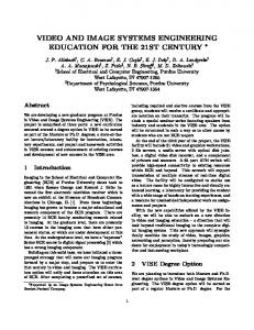
polysilicon electrode
polysilicon inner body
15 nm nitride
5 µm
Figure 1: Left: SEM of 6.2 GHz polysilicon bar resonator (4.3 x 40 x 2 μm). Right: SEM of resonator cross section, showing 15 nm nitride film between polysilicon inner and outer regions.
708
Transducers 2009, Denver, CO, USA, June 21-25, 2009
shown in (a), a Poly0 layer was first deposited and patterned to provide routing to both the resonator and grounding. (b) A sacrificial oxide was deposited and patterned for routing and anchors, (c) followed by deposition of 2 µm of Poly1. The Poly1 layer was patterned with a hard oxide mask to define the inner resonator shape and the position of the dielectric transducers. A 15 nm conformal film of nitride was deposited to form the dielectric transducer, (d) and patterned to define routing and anchors for the outer polysilicon layer. (e) A 2 µm film of Poly2 was then deposited (f) and planarized with Chemical Mechanical Polishing (CMP). The Poly2 layer was then patterned to define the final resonator shape. (g) The resonators were released in a wet etch, followed by metallization. A dielectric thickness of 15 nm was chosen for ease of fabrication and high yield. Scaling the dielectric thickness improves RX following eqn.1. Capacitive electromechanical resonators can be used as passive mixers due to their nonlinear electrostatic actuation. The resonator can thus be characterized by measuring the conversion loss of the mixer. A scalar mixing measurement (Fig. 3) using an Agilent PNA was performed to obtain the frequency response of the resonator. A scalar mixer calibration technique traditionally used to characterize RF mixers was implemented to measure the performance of the high frequency resonators. This method circumvents capacitive losses and parasitic transmission-line resonances in the probe-pads and routing of the 3-port MEMS device and provides an accurate measurement of mechanical Q at frequencies well above 1 GHz.
Internal Dielectric Transduction The underlying difference between ‘internal’ [1,2] and ‘external’ [3] dielectric transduction determines their capabilities at higher frequencies. Both mechanisms employ dielectric drive and sense transducers. External transduction assumes free boundary conditions (zero stress) at the dielectric interface, driving at a frequency corresponding to a resonant mode with maximum displacement at the dielectric, and necessitating maximum acoustic mismatch between the dielectric and resonator bulk. On the other hand, internal transduction incorporates the dielectric film into the resonant mode shape. This generally involves the assumption of a close acoustic match between the bulk resonator and dielectric film. In practice, a mismatch in acoustic impedance between the dielectric and resonator material results in a shift of the resonant frequency, and can easily be compensated by altering the dimensions of the resonator. Theory A longitudinal-mode bar resonator is driven and sensed electrostatically with thin vertical dielectric layers embedded inside the resonator body. The center of the resonator body is biased at VDC, while an ac excitation voltage vin is applied across one dielectric film to excite acoustic vibrations. At resonance, elastic waves modulate the thickness of a second dielectric film in the resonator, generating an output current iout at the other end of the bar. The motional impedance R X ≡ vin iout for the nth harmonic of the resonator is given by [4] nπ Yρ g4 (1) RX = 2 2 2 8QAε f VDC cos (kn d )sin 2 (kn g 2 )
where Y and ρ are the Young’s modulus and mass density of the resonator, respectively. Here, ε f is the dielectric permittivity, g is the dielectric thickness, d is the distance of the dielectric from the center of the bar, A is the transduction area, and k n = nπ L is the acoustic wave number corresponding to the nth harmonic. The increased wave number kn at higher frequencies means that as the acoustic halfwavelength approaches g, the sin2 term in eqn.1 approaches unity, reducing RX with increasing frequency. Furthermore, eqn.1 shows that the position of the dielectric can be exploited to design resonators which preferentially excite higher harmonics [5]. FABRICATION AND MEASUREMENT Fig.1 shows an SEM of a 6.2GHz polysilicon bar resonator. A cross-sectional SEM of the dielectric shows non-porous film quality. The resonators were fabricated in a surface micromachining process illustrated in Fig.2. As
Figure 2: Surface micromachining of dielectrically transduced resonators. The longitudinal resonators are comprised of polysilicon with 15nm silicon nitride transducers.
709
DC supply
LO signal generator
Parametric Network Analyzer
RF input Bias-T
LO + DC
is much higher than that of the 3rd, providing selective 9th harmonic excitation. The RX asymptote for the 9th harmonic at position 2 enables 3rd harmonic excitation with no resonance at the 9th. Finally, the dielectric can be placed at displacement nodes common to both harmonics, as shown at position 3. In this case, both 3rd and 9th harmonics are excited at maximum efficiency. This demonstration of selective mode excitation provides flexibility of design in internal dielectrically transduced resonators. In addition to the study of dielectric position, frequency scaling trends extracted from multiple resonators with optimal dielectric positioning are shown in Fig.5 and 6. The frequency response of 3rd and 9th harmonics of two resonators provides frequency scaling information from 1.55 GHz to 6.20 GHz. The resonant modes across multiple resonators exhibit high f·Q products characteristic of internal dielectrically transduced resonators. The 3rd harmonic resonance 4.7 GHz exhibits an f·Q product of 3.1·1013, the highest f·Q product in polysilicon reported to date. The 9th harmonic at 6.2 GHz is the record high acoustic resonance in silicon to date. The motional impedance of eqn.1 is a function of both harmonic n and quality factor Q. To directly compare resonance with varying harmonics and Q, RX must be normalized as shown in Fig.6. The nominal Q0 for normalization is chosen at 5000. In accordance with eqn.1, the measured internal dielectric transduction efficiency improves with increasing frequency. This result verifies the ability of internal dielectric transduced resonators to scale favorably to even higher frequencies.
RF - LO DUT
Figure 3: Scalar mixer measurement of the 3-port MEMS resonators. The resonator (DUT) acts as a mixer for the input RF and LO signals. The resonance is detected at RF-LO.
EXPERIMENTAL RESULTS The measured motional impedance of the 3rd and 9th harmonics of 8 resonators with varying dielectric position is shown in Fig.4. Since the dielectric transducers are incorporated into the resonant mode, they can be placed anywhere in the resonator body. As dictated in eqn.1, RX follows an inverse cos2 behavior with dielectric position along the bar, and demonstrates minima when the dielectric is placed at a displacement node. Measuring the 3rd and 9th harmonics of longitudinal resonance across 8 different resonators with identical overall dimensions, we can map the RX dependence on dielectric position. As seen in Fig.4, as the dielectric approaches the center of the resonator, transduction efficiency of the 3rd harmonic diminishes to the point where a signal cannot be detected. Meanwhile, the 9th harmonic follows a second minimum in RX towards the center of the bar. With the dielectric at position 1, the transduction efficiency for the 9th harmonic
1
2
no signal
2
3
1
3 |2d/L|
Figure 4: Motional impedance vs. position of dielectric transducer in 3rd and 9th harmonics of 8 different resonators. Selective positioning of dielectric can excite 1 only 9th harmonic at 4.72 GHz, 2 only 3rd harmonic at 1.55 GHz, and 3 both 3rd and 9th harmonics.
710
ability to scale resonators to high frequency without compromising f·Q product. Moreover, the resonator quality factor is limited primarily by anchor losses, and can be improved using thinner routing beams. To maintain high quality factors in integrated applications, the resonators can be encapsulated as described in [6]. These results demonstrate the capacity of internal dielectric transduction to achieve high-Q, high frequency silicon resonators for RF communications and computation.
SC21
In vacuum VDC = 9V RF,LO = 6dBm
Q = 4431
Q = 4880
Q = 6684
Q = 4277
ACKNOWLEDGEMENTS: This work was funded by the National Defense Science & Engineering Grant, Lockheed Martin, and Army Research Labs. The authors thank Dr. Hitoshi Tamada, General Manager of Sony Nanotechnology Development Department, for his continuous encouragement of the international collaboration.
Frequency (GHz)
Figure 5: Measured frequency response of 3rd and 9th harmonics of two bar resonators. The 9th harmonic at 6.2 GHz marks the highest frequency measured in silicon to date.
REFERENCES
Rx normalized to harmonic and Q:
R X = R X ,meas ⋅
[1] D. Weinstein, S.A. Bhave, “Internal dielectric transduction of a 4.5 GHz silicon bar resonator,” IEEE International Electron Devices Meeting (IEDM 2007), pp. 415-418 (2007). [2] M. Ziaei-Moayyed, D. Elata, J. Hsieh, J.-W.P. Chen, E.P. Quevy, R.T. Howe, “Fully differential internal electrostatic transduction of a Lame-mode resonator,” IEEE International Conference on Microelectro mechanical Systems (MEMS 2009), pp.931-934 (2009). [3] Y.-W. Lin, S.-S. Li, Y. Xie, Z. Ren, C.T.-C. Nguyen, “Vibrating micromechanical resonators with solid dielectric capacitive transducer gaps,” IEEE International Frequency Control Symposium 2005, pp.128-134 (2005). [4] D. Weinstein, S.A. Bhave, “Internal dielectric transduction: optimal position and frequency scaling,” IEEE Trans. on Ultrasonics, Ferroelectrics, and Frequency Control, 54(12), 2696-98 (2007). [5] A. Prak, M. Elwenspoek, J.H.J.Fluitman, “Selective mode excitation and detection of micromachined resonators,” Journal of Microelectromechanical Systems 1(4), pp.179-186 (1992). [6] K.-L. Chen, H. Chandrahalim, A.B. Graham, S.A. Bhave, R.T. Howe, T.W. Kenny, “Epitaxial silicon microshell vacuum-encapsulated CMOS-compatible 200 MHz bulk-mode resonator,” IEEE International Conference on Microelectromechanical Systems (MEMS 2009), pp.23-26 (2009).
1 Q meas ⋅ n Q0
f·Q = 3.1·1013 f·Q = 2.7·1013
Figure 6: Motional impedance scaling with resonant frequency. Comparison of resonators with varying harmonics n and quality factors (Q) necessitates normalization of Rx as shown (normalization factor Q0 = 5000). As predicted by theory, Rx improves with increasing frequency.
CONCLUSION We have demonstrated selective excitation of targeted harmonics in polysilicon dielectrically transduced bar resonators by varying dielectric position in the resonator body. We also showed frequency scaling behavior, with improved transduction efficiency at higher frequency. RF resonators up to 6.2 GHz were demonstrated, with f·Q products up to 3.1·1013, the highest reported to date in polysilicon. The high quality factors measured in these internal dielectrically transduced resonators indicates the
CONTACT * D. Weinstein, tel: +1.510.432.8309;
[email protected]
711