David Hampton and Mark S. Whorton. Dr. R. David Hampton. MAE Department. University of Alabama in Huntsville. Huntsville, AL 35899. (256) 890-5083 ...
IMTC
Frequency-Weighting for H2 Control A Consideration
Filter
of Microgravity
of the "Implicit 17,.David
Isolation
them with
with
the requisite
position,
relative
velocity,
filters
can be applied
norm
controllers
however,
since
there
applied
weighting
effects
paper
f'dters,
in
microgravity
Index control,
Terms:
and
state-space
a rational
vibration
isolation
Continuous
linear systems,
the
optimal
time
been
and
among
weight
for intelligent to the
optimal
These
Hz or mixed-
any
practice, frequency
implicit
frequency-
filter
assignment.
of frequency-weighting
among
states
relative design
In
states,
frequency-weighting
coupling
using
characteristics.
states.
assignment
for use
frequency-weighting
the various
other
to provide
planned
modeled
to develop
performance
system
systems
appropriately
in order
relationship
kinematic
isolation
In theory,
models,
approach
of
an active
The isolation
states.
will implicitly
be considered,
presence
have
stability
is a kinematic
must
(ISS)
acceleration
desired
need
environment.
Station
to one state
suggests the
experiments
to these
with
weighting
This
Space
Problem
(256) 544-1435 (Office) (256) 518-9673 (Home) (256) 544-5416 (Fax) (256) 707-3666 (Pager) whortms_,berea, msfc.nasa.gov
microgravity
the International
Weighting"
Dr. Mark S. Whorton NASA Marshall Space Hight Center Huntsville, AL 35812
(256) 890-5083 (Office) (256) 864-2822 (Home) (256) 890-6758 flax) rhanmton@,rnae.uattedu
space-science
Systems:
and Mark S. Whorton
Dr. R. David Hampton MAE Department University of Alabama in Huntsville Huntsville, AL 35899
Abstract--Many
Selection,
Frequency
Hampton
9184
that
exists
design in
the
problem.
systems,
control
control
systems,
feedback
systems,
linear-quadratic
IMTC
9184
I. INTRODUCTION The microgravity difficulty
vibration
and importance
experiments,
unacceptably
disturbances
problem has received
arc by now well known.
and fluid physics science experience
isolation
considerable
high background acceleration
10 Hz) arc a natural accompaniment
about
1 Hz);
power transmission,
processes
Station (ISS),
will
The low-frequency
of space flight with large,
and even
disturbance attenuation [5], especially
were a sufficiently
it could not isolate against direct disturbances to the experiment.
(e.g., for evacuation,
its
excitations.
Passive isolation alone is incapable of providing the necessary
realizable,
Space
levels if not isolated [1]--[4].
flexible, unloaded structures and random, human-induced
range (below
in recent years;
It is anticipated that a number of materials
planned for study on the International
of greatest concern (below
the low frequency
attention
soft
spring
If the experiment
in
physically is tethered
cooling, or material transport), a passive isolator cannot provide
isolation below the comer frequency imposed by the umbilical stiffness. An active stiffness
isolator
(such as a magnetic
suspension
fares no better in the presence of an umbilical,
system
seeks to lower the comer frequency
positive
stiffness)
umbilical
the rattlespace that region
constraints
[6], [7].
particular
and uncertainties, become
possesses
a low positive
Furthermore,
(viz., to counteract
robustness.
is clearly unacceptable.
if the control the umbilical's
In the face of the usual At very low frequencies,
so that any isolation system must have unit transmissibility
In short, the isolator
frequency-dependent
stiffness
almost no stability
this situation
limiting,
that merely
for the same reasons.
by adding negative
the system will at best possess
nonlinearities
system)
must be active;
complexities
and it must be capable
accompanying
a
tethered
payload
of dealing and
in
with the
a
restrictive
the microgravity
vibration
rattlespaee. Various active isolation isolation
problem.
LEvitation"), flown
with
("Microgravity
The
developed USML-2
systems first
jointly on
Vibration
exist or are under development
in space
was
STABLE
by McDonnell
STS-73 Isolation
Douglas
in October Mount"),
1995
developed
2
to address
("Suppression and Marshall [8].
The
jointly
of Transient Space
second
Flight isolation
by the University
Accelerations Center
(MSFC),
system of British
was
By and MIM
Columbia,
IMTC
MPB Technologies,
and the Canadian
Station in April 1996. 1997 [9].
Boeing's
entire International 1996
[10].
Active
[11].
Glovebox
(MSG).
LIMIT,
systems.
facilitate
Linearized
controller H2
Isolation
system
analytical
development
experiment-level
Technology'),
will isolate
building
microgravity
measurements
system models,
for ARIS.
Extensive
tested
payloads
in September
system
(g-LIMIT:
developed
in the Microgravity
available
for control
exist for MIM
has a state-space
design software
in August
to isolate an
STS-79
on the technology
are typically
model
with NASA
aboard
Mir Space
on STS-85
isolation
using these states,
Each
on the Russian
built under contract
a second-generation
design by H2 synthesis.
controller
0VIIM 2) was successfully
System (ARIS),
and absolute-acceleration
and are under
centralized
ofMIM
and placed into operation
Rack (ISPR), was first tested on-orbit
Microgravity
This compact
Relative-position isolation
Payload
is developing
Integrated
STABLE
version
Rack Isolation
Standard
MSFC
"GLovebox
A second
Space Agency,
form
has been written
9184
for
Science
of these
[12], and g-
appropriate
for
in MATLAB
to
design for MIM and g-LIMIT. II. PROBLEM
The
states
of the
analytical
microgravity
isolation
systems
accelerations.
The
acceleration
models
disturbances
rotational acceleration
or
are
assume
disturbances
models
relative the
(i.e., transmitted
subproblem of a mixed-norm forms in the frequency
state-space
positions
experiment indirectly
(i.e., applied
design approach)
for
the and
platform through
directly).
above
six-degree-of-freedom
velocities,
to be subject
the umbilical) Controller
l
3
absolute to indirect
translational translational
and direct translational
design by H2 synthesis
uses a quadratic performance
domain:
and
(6DOF)
and
(or as a
index that has the following
IMTC
where is the frequency-weighted
state vector, and
is the frequency-weighted
control vector.
9184
X y (s) = Wx(s) X (s)
(3)
Uf (s) = W, (s) U(s)
(4)
In particular, 'w_(s) Xt (s) ]
(5)
XiCs) = W2(s)X,(s)_ ; W3(s)X3 (s)J where is the relative
position vector,
is the relative
velocity vector, and
X t (s) = X(s) - D(s)
(6)
X z (s) = s[X(s)-
(7)
X3(s) = m*s2X(s) _ s2X(s) $+0)
represents
the absolute acceleration
closed-loop
acceleration
accommodate resonances,
rattlespace
weighting
filters
to reject
filter
However,
X2(s),
the cost functional)
control
low-frequency
below frequencies
coupling
The
intermediate-range
W,(s)(i = 1, 2,3).
acceleration
ofunmodeled
however,
integrator)
due to the sXl(s),
to a weight
kinematic a frequency
of Iw_(s)on
coupling
large
relative
velocity.
(to
to dampen
is an "implicit the choices
choices
umbilical position
on relative
of these
design W_(s)
stiffiaesses
at low
Xl(s)and
relative
position
Alternatively,
of
frequency
states with some filter
relative
weight of Wl(s)
disturbances
by judicious
there
effective
between
to shape the
system dynamics.
the states, that clouds
to induce
seeks
disturbances,
can be accomplished
In practice, among
engineer acceleration
one might wish to weight relative-position
or an
which equals
large 0_,.
system
(8)
k
so as to pass
of the closed-loop
For example,
a low-pass
frequencies. velocity
constraints),
due to the kinematic filters.
(perhaps
transmissibility
this shaping
frequency-weighting weighting,"
for sufficiently
and to "turn off" the controller
In principle,
O(s)]
such
is equivalent
a weighting
(in
is
$
equivalent
acceleration
to combined
disturbance
weights
s2D(s).
of _W_(s)
There
on absolute
are analogous
acazeleration
implicit
s2X(s)and
effects
of -_21Wi(s) on indirect
due to design
weights
on each
IMTC 9184
other state. weighting states.
In short,
the effective
frequency
weighting
W, (s) and of any implicit frequency
weightings
The net effect of these direct and implicit
without
a rational
weighting
procedure
selections.
In order
The integrand
frequency
to use the cost functional
IlL
is the sum of the direct
due to the effects of kinematic
one can be leR essentially
must first place it into a more suitable
A. Cost-Functional
on X, (s)
weightings
frequency
coupling
can be less than fully intuitive;
with a trial-and-error
approach
to choose
frequency
appropriate
to frequency weights
form. DESIGN
FILTER
of the cost functional
SELECTION
J can be expressed
as
l(s) = I x (s) + I v (s),
(9)
Ix = X*fX f = X_W1°W1X,+ X_W;W2X2 + X;W;W3X_
(1O)
and
= u}u : .
Since H2 or mixed-norm of a control penalty cloud
design mc_&ods require solving
I u couples
intuition
loop tmnsmissibilities "firewall"
in design
filter selection.
can be all but obscured
by assuming
integrand
(M.R.E.),
The relationships
that the control
among
the presence
in a manner
state weightings
that can
and closed-
(such as the one at hand).
This algebraic
is "cheap," an assumption
which permits
l(s) _ I x (s).
relative-velocity-,
and with the substitutions the cost-functional
a matrix Riocati equation
in some problems
1u . Under this assumption,
In terms of relative-position-,
(I I)
the state- and control vectors (through this M.R.E.)
can be partially removed
neglecting
one
Form
where
greatly
among
(12)
and (for low enough frequencies)
Q_ := W_*WI,(i = I,2, 3),
acceleration
states, (13)
is
Zx(,>=(X-D)'Q,(X-D)+Is(X-D)I'Q,I4X-D)I (,4) Let "Txo" and "1 "represent,
respectively,
matrix.
of Txv D forX, the integrand
With the substitution
the closed-loop
transfer
function
from D to X, and the identity
can be written as follows:
IMTC 9184
Theusefulness of theabovetwo formsfor I x in general,
has a uniform
designer's
choice
of control.
frequency-weighting Gaussian,
filters.
and independent
frequency-weighting assumption, brackets
above
spectrum. These
Further,
facts
make
If the acceleration
evident
when one considers
the power spectrum (14)
particularly
disturbance
that neither
of X varies as a function unattractive
s2D
X nor D,
is assumed
for
use
of the
in selecting
to be zero-mean
white
of the control vector, the above form for 1x (jo_) is seen to be more useful for
filter selection
the magnitude
acceleration Wa (s)can
power
becomes
than a form which contains X explicitly.
of s2D does not vary with frequency
require
consideration,
disturbance
is assumed,
be incorporated
in assigning more
oJ, only the terms
frequency-related
realistically,
easily into the square-bracketed
Since, with the white-noise
to be filtered
penalties white
within
with
noise,
the square
Ix(jOo).
ff the
the coloring
filters
portion of (16), by replacing
Q; (i = 1, 2, 3) with
Wd (s)Q_ (s)W_Cs). B. F'dter Selection
Considerations
One can now, with some degree of insight, T,x.,2D(=Txv). transfer
attempt to shape the indirect-acceleration
In doing so, using (16), one must consider
functions in TxD; (2) the alternative possibilities
equivalently,
the _'s);
(1) the desired approximate
for the design frequency-weights
transmissibility shapes (the
of the Qi's, or,
and (3) the effect of the kinematic frequency factors oo-4 and o: z , along with any
disturbance-coloring filters
Wa(s).
Considerations willincludethefollowing: (I) An acceptable closed-looptraasmissibility Txvwillhave unitmagnitude up to some comer fi_equency (e.g.,0.01 Hz), to pass low-frequencydisturbancesthatcannot be attenuatedwithout exceeding
6
IMTC
rattlespace
constraints.
open-loop exciting
It will then drop off in the intermediate
transmissibility high-frequency
curve
dampen
filters
frequency
frequency
relationships these
dependent
factors
fashion.
weightings"
effective
system
s(X-
mass
roll off so that control
factors
X - D dominates
D) should
possible,
J, to
be significant,
intermediate)
will not be required
to
frequencies
for acceleration-disturbance
action
oJ-: (so designated
effectively
off those
In effect,
from the expression
trade the
frequency
directly
equivalent
effects
relative
on the cost functional,
design "machinery."
factors
against
(s2D)
above
some
one
weights
(as previously
they arise from
of the design another,
additional
weight
it might be possible
choice perhaps
in the choice
frequency
that a frequency
velocity
here, because
represent
and would therefore
(However,
the "equivalent"
weights
in the design
for Ix(joJ)
to a weight of 1W_ (s)on s
exactly,
and
must be considered
that do not appear
the choices
o74
among the states)
equivalent
controller
the
range.
kinematic
example,
frequencies,
(and also, to the extent
to increase
State costs should
(3) The "kinematic"
weights;
rejoin
off (e.g., at 100 Hz) to avoid
so that at low frequencies
At intermediate
And at higher
be dominant,
attenuation.
should be selected
to track the stator.
out resonances.
s2Xshould
is to be turned
and finally
system modes.
(2) The frequency-weighting force the flotor
when the controller
frequencies,
9184
place
"implicit
themselves.
only to implement
frequency Observe,
Both choices
equivalent
frequency
in a frequency-
of W_(s)on relative
noted).
the
demands
for
position
would
is
have
on the H2
one or the other of
being unrealizable.)
C. F'dter Choices By building on the above considerations, filters velocity consider
W_(s)for states,
the microgravity and constant
band-pass
filters,
vibration
weighting with poles
it can be shown that a rational choice of frequency-weighting isolation
problem
of all other states. located
would
be band-pass
(Other choices
filtering
are possible.)
at oh and w 2 (co I < to2), to be applied
7
of relative To see this
to the
relative
IMTC
velocities. affects
Assume
that the first and third legs of the filters have 20 dB/deeade
This filter choice
slopes.
lx(jCO) as follows:
1) For low frequencies
(oJ
s = jco
1
will dominate
frequencies
(18)
lx(jCo).
(oh < oJ < oh ), relative
velocity
gains
In this case, s(X-D)
).
if
(19,
(20)
Ix (S). [s(X-V)]°Q 2[s(X - D)]. is significantly
adding damping to the system. frequencies,
In particular,
in significance.
and Q3 in this range,
,x(S)_(s2D)'[_l'xD-I)l-_sQ2)_l'xrj-I)](_2D
Since
(17)
_
l x(/O_)._ (X - D)"QI(X- D) ,
so that relative positions 2)
9184
the controller
weighted
in this region,
there
will be relative
velocity
If the bandpass filter poles bracket any open-loop
feedback,
system
natural
will tend to dampen out those system resonances.
3) Forh/gh frequencies (oJ>>a,2), lx(_)_(s21_'[fxDQsTxD_14Q_1._Q2](s2Z_ 1 • [L
UL_UJJ)
(21)
I s=j
(22)
so thatthecontribution of s2X to lx(JaO willbe significant. Since sZX and Q2 both rolloffat 40 dB per decade,and since QIand Q3 both have zeroslope,allterms of Ix f./a0willhave an 80-dBper-decaderoll-off. This means thatatveryhigh frequencies controlactionwillnot be required: the controller will"turnoff."Note thatifan additional high-frequency poleisadded to Q_ and to Q2 the high-frequency
integrand reduces to
8
IMTC 9184 (23)
Acceleration, then,will dominate In summary, expected
then the use of band-pass
to produce
controllers
H2
Use of these filters leads to
H2
relative
velocity
relative
orientation,
and relative
angular
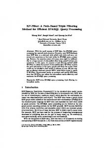
shows the predicted transmissibilities accelerations
directed
frequency-weighting
RESULTING
controllers
figures present typical transmissibility position,
cost.
that address the concerns
IV.
relative
the high-frequency
filters on relative presented
states
in Section
III-B.
that, in fact, yield desirable transmissibilities.
and absolute
acceleration
vibration
acceleration
isolation
measurements
states are reconstructed
to indirect
can be
CONTROLLERS
plots for a microgravity
velocity
previously,
velocity
system that provides
to an H2 controller.
in a Luenberger
disturbances,
along the same axis of an experiment-platform
The following
observer.)
(The Fig. 1
with both input and output
accelerometer.
(The plots are very
similar for the other orthogonal axes.)
ld
OL & CL BODE PLOTS, SUPERIMPOSED
10o
10_
_
10=
"x
16'
..
¢: _,
OL & CL BODE PLOTS, SUPERIMPOSED
,e
//
104
#
C
/ /
f
/
I0 4
lo"/... 10a 104
10"
10"2 10° Frequency (Hz)
10z
104
10'° 10
104
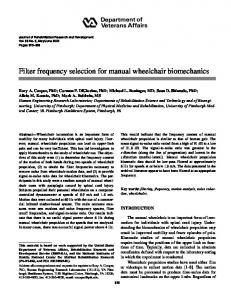
Fa_qu_¢ (Sz) Figure 1. Indirect-Disturbance
Attenuation Figure 2. Direct-Disturbance
Fig. 2 shows the predicted transmissibilities and in the same direction.
to direct translational
disturbances,
{The lower curve in each figure is the closed-loop
9
Attenuation
for the same controller
curve.)
Note that both types
IMTC 9184 of disturbance experience significantattenuation in the0.01Hz to 10Hz fi'equencyrange.As by
the
first
attenuation
figure,
the
indirect
in the range below 0.01 Hz, as required V.
The foregoing weighting I)
treatment
A POSSIBLE
suggests
Develop
a state-space
relative
model
and outputs.
positions,
simply
transmitted
without
constraints.
APPROACIt
general
for the open-loop
(In the microgravity
design
system,
approach,
portion,
approach
for designing
frequency-
with all
inputs
(controls
and
example above, the outputs were
accelerations).
lx(jOJ),
assumes
complete
vibration-isolation
and absolute
state-energy
this means that the present
DESIGN
are
linked states:
relative velocities,
Consider the weighted
disturbances
by rattlespace
the following
filters in the face ofkinematically
disturbances)
2)
(umbilical-induced)
indicated
"cheap
of the quadratic cost functional control.")
Express
lx(jaO
J.
formally
On effect, [i.e., as in
(16)] in terms of the following: a)
a vector consisting positions position
X(s),
of a single,
or absolute
or acceleration
"base"
type of inertial
velocities
disturbances
x_(s),
or absolute
kinematic
quantity
accelerations
[e.g., either absolute
sax(s)---or
B(s) or saD(s), respectivelymbut
even absolute
not a combination
of the
above]; b)
the undetermined
c)
closed-loop
d)
and kinematic
transfer
The base kinematic elements
design frequency-weighting functions
frequency
factors
throughout
whereas
have temporal
velocities
not occur together
(i.e., powers of a_).
coordinates
time be consistent
W_(s)];
[e.g., T:a_(S)];
type may include,
(such as position
filters [e.g., the filters
simultaneously
in one vector,
and orientation angles).
this base vector.
For example,
units of inverse
both translational
It is required
since positions
only that the units of have no temporal
time, these two types of kinematic
in the chosen base vector.
10
and rotational
quantities
units, should
IMTC 9184 3) Choosea desiredapproximate shape closed-loop
transfer
this selection
will subdivide
the microgravity corner
functions
problem
frequency,
frequency [Note:
4)
addressed
weighting
filters.
or kinematic
judiciously, frequency
above,
"turn-off"
CLTF's
the filters
expression regions
plots)
for lx(jO_).
of interest.
transmissibility
attenuation
for each of the
For example,
is desired
is desired
Typically
below
in an
in
some
intermediate
at higher frequencies. CLTF's
are, in fact, achievable.
However,
the
frequency
such that
seeks to cause
factors to aid in the selection
lxO'to ) weights
the desired
appropriately
of the frequency-
the most
region
of interest.
By adjusting
terms
of lx(jto)to
dominate
significant
these
weights
in the appropriate
regions.
The suggested
CONCLUDING
REMARKS
approach, while not a simple, artless procedure,
a degree
of physical
kinematic
coupling
intuition
into the
among the states.
frequency-weighting
Note that this approach
positions
( x - d ) and relative
velocities
approach
can help to inform
the filter-selection
resorting
Bode
can provide a starting point for filter design selection.]
in each frequency
VL
frequency
frequency
unit acceleration
is desired
and the kinematic
quantities,
the designer
into various
that not all desirable
desired,
Choose
in the above
acceleration-disturbance
It should be obvious
CLTF's
appearing
the problem
region, and controller
Use the desired
states
(CLTF's)
maximum
choice of reasonable,
(e.g., as portrayed by asymptotic
weightings
and penetrating
to a mere trial-and-error
does permit the designer to incorporate selection
approach,
when
faced
with
retains its utility with states such as relative
( _ - d ), which include internally
the plant disturbances
task, to aid in threading
the "firewalr'
task, even
of the M.R.E.
the entanglements
This can relieve
and can lead to a considerable
savings
(d).
The
of intrinsic
the designer
of
of time and effort in
the design process. The
method
selections
was
applied
to a 6DOF
microgravity
were shown to produce an effective
H2
vibration
controller.
11
isolation
problem.
Resulting
filter
IMTC
As a final note, for some problems above),
it is possible
matrix(S_)and
(such as the microgravity
to re-express the integrand
a quadratic
in a complementary
readily from (16), by using the substitution TxD appear
as functions
lx(s)as
can then be treated conveniently
the sum of a quadratic
sensitivity-function
SxD =I-TxD
of the i state weighting
vibration isolation
matrix
as a mixed sensitivity
_ (s).
(TaD).
The problem
This can be seen
the weights
on S.m and
of state weight-selection
This will be the subject
problem.
addressed
in a sensitivity-function
• In such reformulations
matrices
problem
9184
of a future
paper. REFERENCES
[1] E. S. Nelson, "An Examination Processes," [2]
NASA TM-103775,
S. DelBasso,
"rhe
AIAA-96-0402, [3]
"System
Space Station
for
the
Microgravity
International
Number SSP41000,
R. DeLombard,
G. S. Bushnell,
C. M. Grodsinsky Microgravity
on Space Station and Its Effects on Materials
Environment,"
The Boeing
Company,
Jan. 1996.
Environment Countermeasures [5]
g-Jitter
Apr. 1991.
International
Specification
Specification [4]
of Anticipated
Space
Station,"
NASA
Johnson
Space
Center,
Rev. D, Nov. 1, 1995. D. Edberg, A. M. Karchmer,
Panel Discussion,"
and G. V. Brown,
Space Experiments,"
B. V. Tryggvason,
AIAA-97-0351,
"Nonintrusive
NASA
and
Inertial
Lewis Research
"Microgravity
Jan. 1997. Vibration
Center, NASA
Isolation
Technology
TM-102386,
for
AIAA-90-
0741, Jan. 1990. [6]
C. Knospe and P. Allaire, "Limitations J.. Spacecraft
[7]
on Vibration Isolation
for Microgravity
and Rockets, vol. 27, no. 6, pp. 642-646, Nov.--Dec.
C. Knospe and P. Allaire, "Limits Experiments,",/..
Spacecraft
on the Isolation
of Stochastic
1990. Vibration for Microgravity
and Rockets, vol. 28, no. 2, pp. 229-237,
12
Space Experiments,"
Mar.--Apr.
1991.
Space
IMTC
[8]
[9]
D. Edbcrg, R. Gouchcr, D. Schcnck, G. Nurrc, M. Whorton, Y. Kim, and D. Alhorn, STABLE
Microgravity
56%581,
1996.
B. Tryggvason, Microgravity
W. Stewart, J. dc Carufcl, Vibration Isolation
Space Agency, [10] G. Bushnell,
AIAA-99-0578, "STS-79
No. SK683-61855-1, [11] M. S. Whorton, NASA Marshall [12] R. D. Hampton, Microgravity
Vibration Isolation
Flight Expcrimcnt," Guidance
and L. Vczina, "Acceleration
and
"Results
Control,
9184
of the
vol. 92, pp.
Levels and Opcration
Mount (MIM) on the Shuttle and the Mir Space Station,"
of the
Canadian
Jan. 1999.
Final Report, RME-1313/ARIS,"
The Boeing
Company,
Boeing
Document
Dec. 1996.
"g-LIMIT:
A Vibration Isolation
System for the Microgravity
Space Flight Center, AIAA-99-0577, B. V. Tryggvason,
Vibration
prcscntexl at the MAG
Isolation
'97 Industrial
L DcCarufcl,
Mount:
Glovcbox,"
Jan. 1999. M. A. Townsend,
A Dynamic
Model
Conf. and Exhib., Aug. 1997.
13
Science
and W. O. Wagar,
for Optimal
Controller
"The
Design,"
IMTC
Figure
Captions:
Figure
1. Indirect-Disturbance
Figure 2.
Direct-Disturbance
Attenuation Attenuation
Final rev. 3/12/00.
14
9184
IMTC 9184
OL & CL BODE
PLOTS,
SUPERIMPOSED
10 2
10 0
10 .2
t--
10 .`=
10 "_
I
10 "s 10 "s
10 4
10 .2
10 °
Frequency
(Hz)
Figure 1. Indirect-Disturbance
]5
10 2
Attenuation
10 4
IMTC
OL & CL BODE PLOTS,
2
SUPERIMPOSED
10
o
10
-2
10
¢-
lo_
/
10
J
-10
10
I
•.6
10
i
4
10
-2
I
0
10
10
Frequency
I
2
10
(Hz)
Figure 2. Direct-Disturbance Attenuation
16
4
10
9184
IMTC
IL David Hampton
17
9184
IMTC
9184
R. David Hampton was born in Annapolis, Maryland, on January 31, 1953. He graduated from the U. S. Naval Academy in 1974, with a Bachelor of Science in mechanical engineering. In 1975 he completed the Master of Engineering in nuclear engineering at the University of Virginia. After several years in the U.S. Nuclear Submarine Force, he returned to the University of Virginia, where he completed a Ph.D. in Mechanical and Aerospace Engineering in 1993. His research interests include the dynamic modeling of multiple-rigid-body systems, using the method of Thomas Kane; and optimal controller design for microgravity vibration isolation systems, for the International Space Station. Dr. Hampton has published several papers on the modeling and control of dynamic systems.
Dr. Mark S. Whorton is an aerospace engineer at NASA/Marshall Space Flight Center in the Precision Pointing Systems Branch of the Control Systems Division. Dr. Whorton received a Ph.D. in Aerospace Engineering from The Georgia Institute of Technology in 1997 and B.S. and M.S. degrees in Aerospace Engineering from The University of Alabama in 1987 and 1989. Dr. Whorton's research interests are in the areas of microgravity vibration isolation systems and robust control for flexible space structures. He is the Principle Investigator of g-LIMIT, a microgravity vibration isolation system for the International Space Station Microgravity Science Glovebox. He was Controls and Analysis Lead for the STABLE project.
18