Trans. Tianjin Univ. 2015, 21: 064-068 DOI 10.1007/s12209-015-2370-7
Friction Stir Welding Effect on Transverse Rigidity and Sound Transmission Characteristics of AZ31B Magnesium Alloy * Luo Zhi(罗
智)1,Hao Zhiyong(郝志勇)1,Ni Dingrui(倪丁瑞)2,Zheng Xu(郑
旭)1
(1. Department of Energy Engineering, Zhejiang University, Hangzhou 310027, China; 2. Shenyang National Laboratory for Materials Science, Institute of Metal Research, Chinese Academy of Sciences, Shenyang 110016, China) © Tianjin University and Springer-Verlag Berlin Heidelberg 2015
Abstract:AZ31B magnesium alloy was subjected to friction stir welding with various welding parameters. The equivalent Young’s moduli of the friction stir welded samples and the base material were obtained by the three-point method, and their transverse rigidities were obtained as well. Furthermore, the sound transmission characteristics of those samples were experimentally studied by four-microphone impedance tube method. The experimental results indicate that the transverse rigidities of the friction stir welded samples were only 79%, 83% and 92% of those of the base material, respectively. The sound transmission losses of the processed samples were also lower, which was largely due to the reduction of transverse rigidities induced by the decrease of equivalent Young’s moduli. Keywords:AZ31B magnesium alloy; friction stir welding; transverse rigidity; sound transmission loss
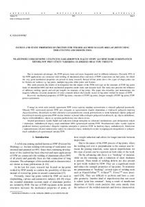
Magnesium alloy is expected to have widespread applications in the fields of communication, automobile and aerospace industry for its excellent physical and mechanical properties, such as low density, high stiffness, high strength to weight ratio, good sound shielding and damping characteristics[1-3]. Refs. [4-6] showed that magnesium alloys may have a promising future as potential degradable implant materials[7]. Welding technology is indispensable for the application of magnesium alloy. However, porosity, coarse microstructure, severe deformation and high residual stress are also introduced to the joints[8]. As a solid state process, friction stir welding (FSW) is not only energy - efficient, but also environment friendly [9]. Before welding, a specially designed rotating tool consisting of a shoulder and a pin is inserted into the edges of the sheets to be welded with a proper tilt angle, until the shoulder gets in contact with the top surface of the sheets, then the rotating tool is moved along the welding line[9-12]. The combined effect of tool rotation and translation involves heat generation, and induces a strong plastic deformation of the work piece, promoting its
complex mixing across the joint[13]. Many problems associated with conventional fusion welding processes can be avoided by FSW. Researchers have studied the microstructure, hardness, texture, fracture and strength of friction stir welded (FSWed) magnesium alloys[14-16]. However, there is few literature on the transverse rigidity (TR) or the sound transmission characteristics. In this paper, AZ31B magnesium alloy was FSWed with different rotation rates and transverse speeds. The TRs were experimentally studied by three-point method. In addition, the sound transmission characteristics were investigated by four-microphone impedance tube method. The same experiments were also conducted on base material (BM) for comparison.
1
Preparation of samples
Along the rolling direction, 2-mm-thick commercial AZ31B rolled plates were FSWed. A steel tool with a shoulder of 12 mm in diameter and a cylindrical threaded pin of 6 mm in diameter was adopted. The welded parameters are listed in Tab.1 as below.
Accepted date: 2014-05-14. *Supported by the National Technology Research and Development Program in the 12th Five-Year Plan of China (No. 2011BAE22B05), CanadaChina-USA Collaborative Research and Development Project (No. 2011DFA50900). Luo Zhi, born in 1983, male, doctorate student. Correspondence to Hao Zhiyong, E-mail:
[email protected].
Luo Zhi et al: Friction Stir Welding Effect on Transverse Rigidity and Sound Transmission Characteristics of AZ31B Magnesium Alloy Tab. 1
Welded parameters of FSWed samples Transverse speed
Rotation rate
Sample
n/(r·min )
v/(mm·min 1)
3 000
2 000
-1
FSW1
-
FSW2
800
200
FSW3
3 000
200
samples were intact and the load can be considered as a static excitation. The equivalent Young’s modulus E and flexural stiffness CR [18] can be written as 3R 2 B ( ) S0 (1 2 ) S p (1) E 2πh3 CR
3R 2 S p
(2) Circular samples with radius of 75 mm were cut off 2πh3 from the welded plates, and the welded line coincided where h is the thickness of samples; is Poisson ratio; with the diameter of those samples. The schematic of and B( ) is a function of , i.e., FSWed AZ31B magnesium alloy sample is shown in Fig. 1. 4 π [2 ln 3 (1 )(π 3 3)] B ( ) (1 )(3 ) 27 ( 1) 2 2(3 )(1 )
SZ——stir zone; TMAZ——thermo-mechanically affected zone; HAZ——heat affected zone
Fig. 1 Schematic of FSWed AZ31B magnesium alloy sample
2
(3)
R is the radius of supporting circle, as shown in Fig. 2(a); S p is the modified slope of load-displacement curves, i.e., S0 Sp (4) 4.1R /(2 R ) 0.59(1 e ) 1
where S0 is the slope of load-displacement curves. Fig. 3 shows the equivalent Young’s moduli of BM and FSWed samples.
TR experiment
The TR experiment was performed by the threepoint method[17,18], as shown in Fig. 2.
Fig. 3 Equivalent Young’s moduli of BM and AZ31B magnesium alloy with different FSW parameters
(a) Schematic of three-point method
Fig. 2
(b) Experimental set-up
TR experiment
All the experiments were performed with an electromechanical testing machine Zwick-Roell Z010. The experimental data were recorded by Textexpert 8.1, Zwick-Roell. The circular samples were placed upon the supports. The head of indenter and the supports were designed to be spherical, so the samples were less likely to be destroyed. Meanwhile, the speed of indenter was set to be 0.08 mm/s, which was small enough. As a result, the
The equivalent Young’s modulus of BM is 44.2 GPa, while the equivalent Young’s moduli of FSW1, FSW2 and FSW3 are 95%, 86% and 81% of that of BM, respectively. Singh et al[19] found that the reductions of the Young’s modulus of FSWed aluminium 7136-T76 samples are probably caused by the microstructural pores, microstructural cracks or some other defects formed along the weld line. During FSW, there is always a gap between two BMs regardless of the pressure of clamping fixture, so the pore is produced near the welding line. If the welding rate is too fast, the pore cannot be filled in time and a defect will occur in the weld[20]. In addition, higher cooling speed causes higher stress concentration in the interface, which will result in welding cracks during cooling[21]. Moreover, HAZ usually con—65—
Transactions of Tianjin University
Vol.21 No.1 2015
tains a large amount of coarsened grains with relatively lower yield strength than that in TMAZ and in the nugget, which is believed to be the weakest place for the crack initiation during the experiments of fatigue performance and tensile strength[22]. However, as shown in Fig. 1, the radius of FSWed samples is 75 mm, so it is hard to determine the positions of those possible defects. The TRs of tested samples are shown in Fig. 4.
Fig. 5
Set-up of sound transmission loss experiment
As shown in Fig. 5, the white noise signal generated by generator is amplified by the power amplifier and emitted through the speaker to form a plane wave field in the impedance tube. The plane sound wave propagates toward and impinges on the sample. The reflected plane sound wave is produced with the sample, while the sound transmitted propagates toward the terminal, approximating anechoic termination that was made of loosely packed sound-absorbing material. The re-reflected wave is neglected, because it is very weak[24]. As shown in Fig. Fig. 4 TRs of tested samples 5, there are two microphones in the upstream and downIt is obvious that the TRs of all the FSWed plates stream of the impedance tube, respectively. The sound are lower than that of BM. The TR of BM is 51.83 GPa, pressure at microphones 1—4 are as follows: while the TRs of FSW1, FSW2 and FSW3 are 92%, 83% p1 ( A jkx B jkx )e jt (5a) and 79% of that of BM, respectively. As shown in Fig. 3, p2 ( A jkx B jkx )e jt (5b) the equivalent Young’s moduli of FSWed samples are lower than that of BM, which is the main reason for the p3 (C jkx D jkx )e jt (5c) reduction of TRs of the FSWed samples. The thickness p4 (C jkx4 D jkx4 )e jt (5d) reduction of SZ is also a possible reason for the reduction of TRs, because the work pieces were pressed by the where k is the wave number in the ambient fluid; is the circular frequency; j 1 ; x1 — x4 are the coordishoulder during welding. The ratio of rotation rate to traverse speed n / v is an nates of microphones 1—4, respectively; A — D are the important parameter, because it represents heat input in complex amplitudes of the four waves, and they can be the FSW process. The values of n / v of FSW1, FSW2 derived by the combination of Eqs. 5(a)—5(d), e.g., 1
and FSW3 are 1.5, 4.0 and 15.0, respectively. The increased heat input results in material softening in SZ, and TMAZ is also possibly affected. Furthermore, the increased ratio of n / v results in the formation of a larger weld nugget because of an increase in heat input and an easier material flow[23], and this is the reason for the reduction of TRs.
3
—66—
2
2
3
3
A
j( p1e jkx2 p2 e jkx1 ) 2sin k ( x1 x2 )
(6a)
C
j( p3 e jkx4 p4 e jkx3 ) 2sin k ( x3 x4 )
(6b)
Then the STL can be given by C STL 20lg A
Experiment of sound transmission char4 acteristics
Four-microphone impedance tube method was employed to study the sound transmission loss (STL) of FSWed samples, and the STL of BM was also obtained for comparison. Fig. 5 shows the schematic of the experiment.
1
(7)
Results and discussion
The STLs of tested samples are shown in Fig. 6. The STL of BM is higher than those of all the FSWed samples, while FSW3 has the lowest STL among all the other FSWed samples. However, the STLs of all the samples do not have many differences in the range of 400—1 000
Luo Zhi et al: Friction Stir Welding Effect on Transverse Rigidity and Sound Transmission Characteristics of AZ31B Magnesium Alloy
Hz. The differences are obvious in the range of 1 000— 1 300 Hz. At the anti-resonant frequency of FSW3, i.e., 1 300 Hz, the STL of BM is 4.68 dB, 15.8 dB and 28.75 dB higher than that of FSW1, FSW2 and FSW3, respectively.
tion of TRs, the STL was also reduced. At the antiresonant frequency of FSW3, the STL of BM was 4.68 dB, 15.8 dB and 28.75 dB higher than that of FSW1, FSW2 and FSW3, respectively. References [1] Kulekci M K. Magnesium and its alloys applications in automotive industry[J]. The International Journal of Advanced Manufacturing Technology, 2008, 39 (9/10): 851-865. [2] Friedrich H, Schumann S. Research for a “new age of magnesium” in the automotive industry[J]. Journal of Materials Processing Technology, 2001, 117 (3): 276-281.
Fig. 6
STLs of tested samples
As discussed in Section 3, BM has a higher TR than those of the FSWed samples. The frequency ranging from 400 Hz to the anti-resonant frequency is the stiffness control region of the curve of STL[25], so the STL of BM is higher than those of the FSWed samples. On the other hand, the samples with higher TRs have higher natural frequencies than those with lower TRs. Therefore, as frequency increases, the samples with lower TRs reach their anti-resonant frequencies before those with higher TRs. So the STL characteristics of the tested samples will reverse when the frequency is higher than the anti-resonant frequency of BM or lower than 2 000 Hz. The STL of FSW3 is higher than those of all the other FSWed samples, and STL of BM is the lowest of all the tested samples. The FSW effect on the damping of BM should be studied further, because the damping loss factor is possibly influenced by the grain size, recrystallization effect and any other microstructural changes as well.
[3] Tang Y M, Zhao X H, Jiang K S et al. The influences of duty cycle on the bonding strength of AZ31B magnesium alloy by microarc oxidation treatment[J]. Surface and Coatings Technology, 2010, 205 (6): 1789-1792. [4] Gu X N, Zheng Y F, Cheng Y et al. In vitro corrosion and biocompatibility of binary magnesium alloys[J]. Biomaterials, 2009, 30 (4): 484-498. [5] Hänzi A C, Gerber I, Schinhammer M et al. On the in vitro and in vivo degradation performance and biological response of new biodegradable Mg-Y-Zn alloys[J]. Acta Biomaterialia, 2010, 6 (5): 1824-1833. [6] Zhang S X, Zhang X N, Zhao C L et al. Research on an Mg-Zn alloy as a degradable biomaterial[J]. Acta Biomaterialia, 2010, 6 (2): 626-640. [7] Wang Y M, Guo J W, Shao Z K et al. A metasilicate-based ceramic coating formed on magnesium alloy by microarc oxidation and its corrosion in simulated body fluid[J]. Surface & Coatings Technology, 2013, 219: 8-14. [8] Zhou L, Nakata K, Liao J et al. Microstructural characteristics
5
Conclusions
and
mechanical
properties
of
non-
combustive Mg-9Al-Zn-Ca magnesium alloy friction stir welded joints[J]. Materials and Design, 2012,42: 505-512.
AZ31B magnesium alloy was FSWed with different welding parameters. The TRs and STLs of those welded samples were tested by three-point method and fourmicrophone impedance tube method, respectively. It is observed that the equivalent Young’s moduli of FSW1, FSW2 and FSW3 were only 95%, 86% and 81% of that of BM, while the TRs were only 92%, 83%, and 79% of that of BM, respectively. The reduction of TRs of FSWed samples was mainly induced by the reduction of their equivalent Young’s moduli, which possibly resulted from the defects formed during welding. Because of the reduc-
[9] Thomas W M, Nicholas E D, Needham J C et al. FrictionStir Butt Welding: UK, 9125978. 8 [P]. 1991-12. [10] Mishra R S, Ma Z Y. Friction stir welding and processing[J]. Materials Science and Engineering R, 2005, 50 (1/2): 1-78. [11] Nandan R, DebRoy T, Bhadeshia H K D H. Recent advances in friction-stir welding — Process, weldment structure and properties[J]. Progress in Materials Science, 2008, 53 (6): 980-1023. [12] Simar A, Bréchet Y, de Meester B et al. Integrated modeling of friction stir welding of 6xxx series Al alloys:
—67—
Transactions of Tianjin University
Vol.21 No.1 2015
Process, microstructure and properties[J]. Progress in
and Technology of Welding and Joining, 2010, 15(2): 142-
Materials Science, 2012, 57 (1): 95-183.
148.
[13] Commin L, Dumont M, Masse J E et al. Friction stir
[20] Gharacheh M A, Kokabi A H, Daneshi G H et al. The
welding of AZ31 magnesium alloy rolled sheets: Influence
influence of the ratio of “rotational speed/traverse speed”
of processing parameters[J]. Acta Materialia, 2009, 57
(w/v) on mechanical properties of AZ31 friction stir
(2): 326-334.
welds[J]. International Journal of Machine Tools and
[14] Woo W, Choo H, Prime M B et al. Microstructure, texture
Manufacture, 2006, 46(15):1983-1987.
and residual stress in a friction-stir-processed AZ31B
[21] Zhang H, Lin S B, Wu L et al. Defects formation proce-
magnesium alloy[J]. Acta Materialia, 2008, 56 (8): 1701-
dure and mathematic model for defect free friction stir
1711.
welding of magnesium alloy[J]. Materials and Design,
[15] Esparza J A, Davis W C, Trillo E A et al. Friction-stir welding of magnesium alloy AZ31B[J]. Journal of Materials Science Letters, 2002, 21(12): 917-920. [16] Xin R L, Liu D J, Li B et al. Mechanisms of fracture and
2006, 27(9): 805-809. [22] Chen Y C, Nakata K. Friction stir lap joining aluminum and magnesium alloys[J]. Scripta Materialia, 2008, 58(6): 433-436.
inhomogeneous deformation on transverse tensile test of
[23] Chen C M, Kovacevic R. Finite element modeling of fric-
friction-stir-processed AZ31 Mg alloy[J]. Materials
tion stir welding—Thermal and thermomechanical analy-
Science and Engineering: A, 2013, 565: 333-341.
sis[J]. International Journal of Machine Tools and Manu-
[17] Bassali W A. The transverse flexure of thin elastic plates supported at several points[J]. Proceedings of the
facture, 2003, 43(13): 1319-1326. [24] Yacoubou S, Raymond P. A general wave decomposition
Cambridge Philosophic Society, 1957, 53: 728-743.
formula for the measurement of normal incidence sound
[18] Nunes J P, Pouzada A S, Bernardo C A. The use of a three-
transmission loss in impedance tube[J]. The Journal of the
point support flexural test to predict the stiffness of anisotropic composite plates in bending[J]. Polymer Testing, 2002, 21 (1): 27-33. [19] Singh K V, Hamilton C, Dymek S. Developing predictive tools for friction stir weld quality assessment[J]. Science
Acoustical Society of America, 2009, 125 (4): 2083-2090. [25] Lee C M, Xu Y. A modified transfer matrix method for prediction of transmission loss of multilayer acoustic materials[J]. Journal of Sound and Vibration, 2009, 326 (1/2): 290-301. (Editor: Wu Liyou)
—68—