From Activity Diagrams to Class Diagrams João-Paulo Barros1, Luis Gomes2 1 Instituto Politécnico de Beja ,Escola Superior de Tecnologia e Gestão, Área Departamental de Engenharia 7800-050 Beja, Portugal,
[email protected] 2 Universidade Nova de Lisboa, Faculdade de Ciências e Tecnologia, Department of Electrical Engineering, 2825-114 Monte de Caparica, Portugal,
[email protected]
Abstract. A translation from activity diagrams to class diagrams, with executable code, is presented. The translation is amenable to be made with or without automating tools. An illustrative application example is also briefly presented: Activity diagrams are used in the modelling and implementation of graphical user interfaces, more precisely in the controller part of the Model-View-Controller pattern.
1
Introduction
It is well know the difficulty in maintaining consistency across different views of the same system. The use of the Unified Modelling Language (UML), with their multiple diagrams, can easily give origin to inconsistencies. The UML is more easily perceived as a union of modelling languages than as unification. As most systems revolve around the class diagram, its generation is usually given high priority. Nevertheless, many times, and particularly in event driven systems, a behavioural model is a much more easy and intuitive starting point. Among the behavioural models, the activity diagram is usually not given much attention. This is unfair as the activity diagram is actually very versatile and can be easily used by users with very different backgrounds, namely in, procedural programming languages, flowcharts, state machines, Petri nets and workflow systems. Note that this list includes almost all kinds of designers with some previous experience in the modelling of dynamic systems. This paper presents an easily applicable translation of activity diagrams to class diagrams. This can be applied to any kind of system. One case study is briefly presented for modelling of the controller part of a Model-View-Controller pattern through the use of an activity diagram.
2
Activity Diagrams
As stated in the UML specification [1], an activity diagram is a variation of a state machine. Depending on the background of the user, an activity diagram can seem like a flowchart, a Petri net or some kind of workflow modelling notation. It allows a very
readable modelling of concurrency and of all elementary programming concepts, namely: sequence, branch, loop, fork and join [2]. Activity diagrams are usually associated to a class and, as such, they model the operations flow inside the class. This flow can depend on internal or external events. Nevertheless, the activity diagram also allows a hierarchical decomposition, through the use of subactivity states [1], and so it can model several classes related by class aggregation. Through the use of external events we can even synchronise several activity diagrams.
3
Translation of Activity Diagrams to Class Diagrams
The proposed translation has the following objectives: 1. To be sufficiently simple so as to be routinely and consistently used, even without supporting tools 2. To be sufficiently rigorous so as to amenable to automatic translation by supporting tools The emphasis on this paper is on the manual translation of activity diagrams to class diagrams. The result of this translation process will be presented by the description of the resulting class diagrams representation with an associated code skeleton. The simplicity of the generated translation, namely its external interface, allows an easy integration with code generated from other models by other methods. Proposed translation Activity diagrams
General purpose UML Tool Activity diagrams
Meta model
Meta model
(b) Class diagrams with embedded code
Meta model
Translation component
Class diagrams with embedded code
Meta model Code (a)
Code (b)
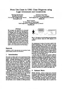
Fig. 1.Proposed translation (a) and ultimate goal (b)
Figure 1(a) shows the referred process where UML meta models are implicitly considered for the translation support (although not generated as they are not amenable for manual editing). The ultimate goal of the present proposals is to support the development of a software component, which will implement the proposed translation process. This component, based on UML meta models, will be amenable to be used inside a autonomous translation tool or integrated with a general purpose UML based development tool. This is illustrated in Figure 1(b). In the next sections, we present the translation details.
3.1
General Procedures
When translating activity diagrams to class diagrams each activity diagram will map to one class in the class diagram. Activity diagram in subactivity states are translated to aggregated classes. This is in accordance with the subactivity specified semantics which states that single activity graph may be invoked by many subactivity states. All activity diagram elements are translated to class elements in the following way: • Each event maps to an event object. Each event object has a state (active or inactive), a list of associated transitions and a method that calls all the associated transition methods. All event objects are made elements of an event vector which is a class attribute. • Each action state maps to an action state object. All action state objects are made elements of an action state vector, which is a class attribute. • Transitions, decisions, merges, forks and joins, map to class methods as presented in the following sections. • Subactivity states map to attributes. Each of these attributes belongs to a class translated from the activity diagram associated to the subactivity state. The action state objects have four methods and one state attribute: IsActive(); SetActive(); SetInactive(); Action(); state.
The first method is a Boolean function that returns the object state (active or inactive). The second and third ones change the state of the object and the fourth one executes the associated action specified in the action state.
a)
AS1action()
st1
AS2action()
b)
AS1action()
st1 ev
AS2action()
Boolean st1() if (cas[1].isActive()) as[1].action(); as[1].setActive(); as[2].setActive(); return TRUE; else return FALSE;
Fig. 2 - Transition translation. One implicit event (a) and one explicitly specified event (b), between two action states give origin to the same transition method.
Each transition is mapped to a Boolean method that returns true if the transition can fire and false otherwise (Figure 2). Here the term transition is considered in a much more broader sense than in the activity diagrams specification, as all the set of all arcs, control icons, decisions and merges between two or more action states are considered part of a transition. In other words, all inscriptions, arcs and nodes between action states are considered part of the same transition and are translated to only one method. We will call this broader concept of transition, super-transition so as to distinguish it from the transitions in the activity diagrams definition [1]. As the transition method is called by the activating event (ev in Figure 2), the transition can fire depending of its previous states as well as of eventual guards (Figure 2). If input states to the super-transition are active the method does the following: executes the action associated with the input action state (AS1action() in
Figure 2); inactivates the input actions states, activates the output action states; returns true to signal success. Note that the testing of the action states activation is made based on a copy of the action states objects (as will be detailed in §4). The translation of both super-transitions is the same. In case (a) the implicit event calls the method, in case (b) the event ev calls the method. The implicit event is always active so as to support this behaviour. The name st1 is only for illustrative purposes as it is not part of the activity diagrams, instead it is generated as part of the translation process. The situation where an input event occurs but some or all associated transitions are not enabled can have two disjoint interpretations: it is an exceptional but allowed occurrence; it exposes a design error that should be detected during test or verification phase. If that is the case, the action states activity or inactivity act like pre-conditions that if not met will imply a design error. It is also interesting to consider the possibility of event methods with parameters, which are passed to transition methods.
3.2
Translation of Decisions and Merges
As already stated, decisions and merges are considered part of super-transitions. They typically have several possible inputs and/or outputs. The mapping follows the same basic structure of the simple transitions and adds decision structures to support the multiple possible flows. Figure 3 presents an illustrative example.
AS1action() st1 ev
a > 0 AS3action() else
st2
Boolean st1() if (cas[1].isActive()) as[1].action(); as[1].setInactive(); if (a > 0) as[3].setActive(); else as[2].setActive(); return TRUE; else return FALSE;
Boolean st3() if (cas[4].isActive()) as[4].action(); as[4].setInactive(); as[2].setActive(); oev.setActive(); return TRUE; else return FALSE;
AS2action()
AS4action() st3 oev
Boolean st2() for(c = 2; c