The recursive formulation allows to express the multi-way parti- tioning problem as .... directly impacts power consumption assuming equal switching activities on ...
45.5
From Architecture to Layout: Partitioned Memory Synthesis for Embedded Systems-on-Chip L. Benini �
L. Macchiarulo z
A. Macii z
E. Macii z
M. Poncino z
�
z
Universit�a di Bologna DEIS Bologna, ITALY 40136
Politecnico di Torino DAI Torino, ITALY 10129 Abstract
We propose an integrated front-end/back-end ow for the automatic generation of a multi-bank memory architecture for embedded systems. The ow is based on an algorithm for the automatic partitioning of on-chip SRAM. Starting from the dynamic execution pro le of an embedded application running on a given processor core, we synthesize a multi-banked SRAM architecture optimally tted to the execution pro le. The partitioning algorithm is integrated with the physical design phase into a complete ow that allows the back-annotation of layout information to drive the partitioning process. Results, collected on a set of embedded applications for the ARM processor, have shown average energy savings around 34%.
1 Introduction
A key challenge in low power design for Systems-on-Chip (SoC) containing embedded cores and memories is to reduce the power consumed in accessing memory [1, 2, 3, 4]. Data memory accesses are critical for power in data-dominated embedded applications (e.g., MPEG decoding, speech processing, etc.), and they are harder to deal with than instruction accesses, because they tend to be more irregular. Nevertheless, the critical relevance of data memory energy reduction has been stressed by many authors [2, 3], and a number of system-level data memory optimization techniques have been proposed. One of the most e�ective solutions is memory partitioning. The rationale in this approach is to sub-divide a large memory into many smaller memories that can be accessed independently. Energy-per-access is reduced because on every access only a single small memory consumes power, while all the others remain quiescent. Memory designers and computer architects have long ago acknowledged the importance of partitioning, and many circuit design techniques [5, 6, 7], as well as architectural optimizations [8, 9, 10, 11, 12] have been proposed to partition (i.e., sub-bank) memories and improve energy e�ciency. The full potential of memory partitioning can be exploited by focusing jointly on how to partition the memory space and how to distribute memory accesses in the partitioned memory architecture. Permission to make digital or hard copies of all or part of this work for personal or classroom use is granted without fee provided that copies are not made or distributed for pro t or commercial advantage and that copies bear this notice and the full citation on the rst page. To copy otherwise, or republish, to post on servers or to redistribute to lists, requires prior speci c permission and/or a fee. DAC 2001, June 18-22, 2001, Las Vegas, Nevada, USA. Copyright 2001 ACM 1-58113-297-2/01/0006...$5.00.
784
For embedded systems, it is possible to tailor a memory partition to a given target application. This objective can be achieved by analyzing data accesses with either data ow analysis [2, 3], or execution pro ling [13]. A key point in application-speci c memory partitioning techniques is how to take into account the overhead that comes with a partitioned memory: (i) Power and area of the control logic for memory selection and addressing; (ii) Area growth caused by the instantiation of multiple memory banks as opposed to a monolithic memory; (iii) Timing bottlenecks and additional power caused by bus multiplexing. Most of the overhead becomes apparent only at the physical design level, when a partitioned memory architecture is placed and routed. Current automatic memory partitioning techniques [2, 3, 13] do not fully address this issue. This paper proposes an integrated optimization approach that starts from an embedded application targeted for a processor family, and outputs a complete layout, fully placed and routed, of a power-optimal partitioned memory, tailored for the chosen embedded application. The layout includes memory macros, core, addressing and memory selection logic, control signals and system buses. Our optimization algorithm takes layout-related overhead into account both during top-down optimization and bottom-up validation. The rst objective is achieved thanks to a preliminary analysis, that can be run once and for all for a given technology, and that leads to a precise pre-characterization of the expected partitioning overhead to be used by the memory partitioning algorithm. Overhead estimation is exploited by the partitioning algorithm to speed-up its search for a poweroptimal partition. The second objective is achieved by developing a seamless ow that integrates high-level memory partitioning, logic synthesis, placement and routing, parasitic extraction and back annotation, timing, area and power analysis. Results show that the architecture-to-layout approach provides: (i) Dramatic power reductions, since it allows us to tighten the safety margins during optimization; (ii) Precise control of side constraints (timing, area) during power optimization; (iii) Onepass optimization, without the need of iterations in the timeconsuming physical design step. The partitioned memory architectures obtained with the proposed approach result in energy savings of 34% on average (54% maximum), estimated on actual layouts.
2 Memory Partitioning Algorithm
In [13], an algorithm for the automatic partitioning of the memory space of an embedded application into multiple memory banks was proposed. We have enhanced the search engine de-
Concerning cycle time, the address decoder that activates the various memory banks increases the cycle time of the system; on the other hand, the cycle time imposed by the memories can be reduced because smaller memories are used. Concerning area, partitioning into multiple banks intuitively increases the total area. However, the actual overhead can be much smaller than expected because smaller blocks may be placed more easily. � Design ow integration issues: The implementation of the algorithm within a realistic design ow requires the adoption of some approximations to trade-o� execution times of the partitioning algorithm with the optimality of the produced solution. For example, although the algorithm is able to generate partitions of any size, their actual size is bound to the rules of a real-life automatic memory generator. Addressing all the issues listed above is key for enabling a complete design path, from architecture to layout. Among the above issues, the accurate estimation of the partitioning overhead is de nitely the most critical. The solution we propose is based on the idea of linking together the partitioning tool (the front-end) with physical-design tools (i.e., back-end) and thus of supplying the partitioning algorithm with realistic overhead data calculated after layout. Details on the front-end/back-end integration
ow are provided in the next section.
veloped in that work to allow a tighter integration in the architecture-to-layout ow. For a better understanding of the modi cations required by the integration with the back-end, we will brie y outline its main features. The algorithm is formulated as an optimization problem consisting of the computation of a set of memory cuts, up-to a maximum of Max blocks, on an abstract view (an array of M locations) of the data memory to be partitioned. The optimum cut set is computed using a recursive, branch-and-bound algorithm driven by a cost function that models the overall memory energy used by the target application during its execution. The recursive formulation allows to express the multi-way partitioning problem as a set of bi-partitioning instances. At a given recursion depth, l, it is assumed that the rst l;1 cuts have been already computed; the last cut is obtained by bi-partitioning the remaining block of memory. An e�cient bi-partitioning algorithm is thus central to the overall partitioning process. Because of the size of the overall search space, e�ective bounds are needed to make the exploration feasible. The algorithm uses two bounds to prune the search space. The rst one is imposed by the physical interpretation of the partitioning process; that is, the feasibility of a partition is subject to the fact that the energy overhead of an extra bank is properly amortized. This fact is modeled as an array � = [0; �1 ; : : : ; �Max-1 ]; �i expresses the energy overhead imposed for moving from i ; 1 to i memory partitions (�0 is referred to the case of the monolithic memory). This implies that a bipartition at a given recursion depth l is rejected if this does not improve the current minimum of at least �l . The second bound exploits a peculiar property of the energy cost function used to drive the partitioning process. This cost function is obtained by multiplying two monotonically increasing functions of memory size: The energy for a read/write memory access and the total cumulative read/write access counts. Therefore, by construction, the energy cost function is also monotonically increasing with respect to memory size. This implies that, as soon as the � constraint is violated, say, at a given iteration i, further iterations on values k > i can be avoided because the energy consumed in those memory blocks will be larger. The algorithm of [13] solves the partitioning problem from an abstract point of view. However, practical application of the algorithm to a realistic memory partitioning framework must take into account several additional factors, possibly trading o� optimality for exibility. The following are important issues that were not considered in the original algorithm: � Accurate estimation of the energy partitioning overhead: In the original algorithm the �s were estimated in a conservative way, under reasonable assumptions on the placement of the memory blocks. The energy partitioning overheads should be computed using information back-annotated from actual layouts; this requires the integration of the memory partitioning program in a complete design ow. Accurate evaluation of hardware overhead is key for an effective use of the partitioning tool, because it allows the exploration of partitioning alternatives at the application level, without the need of interacting with the back-end framework for each partitioning solution. � Cycle time and area constraints: Although energy optimization is the primary target, the optimum partitioning solution should not violate possible user-speci ed cycle time and area constraints. From the algorithmic point of view, constraints are easily taken into account by specifying a set of relative penalties, similarly to the energy overhead �s.
3 Physical Design of Partitioned Memory
Accurately taking into account the partitioning overhead (added logic to compute the real addresses, added loads due to wiring, placement constraints) during optimization and validation is essential for calculating a realistic memory partition. In this section, we discuss the physical design ow that we have developed. The input of the ow is the list of partitions produced by the tool described in Section 2, and its output is a legal layout of placed and routed blocks, that is, the core and memory system, including address decoder and memory selector. A back-end ow manager automatically takes care of all the phases of the physical design, all the way down to detailed routing. The following are the main steps of the ow, that are described in detail in the following subsections: � Decoder generation; � Memory generation; � Block placement; � Block routing; � Power/ Delay/Area estimation. The target technology is a 0:25�m process from ST Microelectronics, with six levels of metal (only the rst two levels were used for signal routing between blocks). Memory blocks are synthesized using ST's embedded SRAM generators, that provide accurate timing, area and power information for the various memory cuts. The generators allow the user to specify ne details of the internal memory organization (such as bu�er parametric sizing, various degrees of output multiplexing, etc.). Since we target power minimization, the internal structure of the memory banks has been speci ed so as to minimize energyper-access during read and write cycles. The processor that interfaces with the customized memory system is an ARM9 core [14]. The control and addressing logic are synthesized in standard cell style onto the 0:25�m low-power HCMOS library from ST Microelectronics.
785
3.1 Decoder Generation
columns. This choice, however, could be suboptimal in terms of delay and/or area. Two features of the generated memories are particularly attractive for the proposed ow. First, the functional signals (control, data and address buses) are to be accessed on the same side of the memory: This allows easier oorplanning (as shown in next section) and simpli es thus the physical design phase. Second, the memories can be turned o� rapidly, so that it is possible to activate and deactivate a memory block at every clock cycle without impairing the performance of the whole system.
The knowledge of the cut points for the addresses is used to generate a synthesizable Verilog description of a block (the decoder, hereafter) that interfaces with the CPU to translate its addresses and control signals into the multiple control and address signals needed to drive the various memory banks. The decoder takes the address lines of the core as inputs, and produces two output signals: � Memory select: According to the interval of the virtual address issued by the core, it selects and activates the memory block that physically maps that address. � Physical address: The virtual address has to be re-scaled to the address w.r.t. the selected memory bank. For example, if the second bank maps the virtual addresses starting from the virtual (CPU) address of 1FFF to address 2FFF, when the issued address is between those two limits, the physical address has to be equal to virtual address{1FFF The Verilog description is synthesized using Synopsys Design Compiler, that maps it on the standard cell library. The synthesis is timing- driven to ensure that the nal implementation will not su�er from performance degradation. The technology mapped decoder is then passed to a commercial place and route tool (Cadence Silicon Ensemble), together with the description of the standard cell library, to obtain a standard cell implementation. The result of this phase is an independent block which has to be placed and routed together with all the other blocks of the design. This \hierarchical" solution has been chosen, instead of routing the standard cell netlist together with the memory blocks, for two reasons: power distribution uses metal-2 lines inside the standard cell structure, while power distribution in the overall system uses levels 3 and 4 of metal; this would cause con icts with standard cell power routing. This approach is consistent with common practice P&R tools that usually deal separately with block and cell routing, by cutting out an area explicitly for block design out of the standard cell area. Second, the area of the decoder with respect to the CPU core and memories is very small. Therefore, having the decoder enclosed in a small atomic block helps the task of the global placer and router, because it will tend to place the decoder close to the address pins of the core representing its primary inputs.
3.3 Block Placement
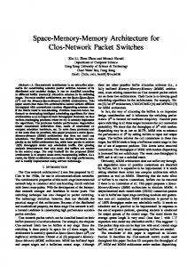
After the memory cuts are generated and the decoder synthesized, it is possible to place them on the die. We explored two di�erent choices for the placement phase: (i) A fully automated strategy, with no insight on the functionality of the blocks, that relies on the block-placer contained in Silicon Ensemble to enforce minimal wire length; (ii) A directed oorplanning strategy, which uses the knowledge of the position of the pins and the functionality of the blocks to ease the routing phase. Out of the many choices for regular placement, we explored that of a bus-channel arrangement, in which the blocks are placed as in Figure 1. mreq A D
CPU Core A1
CS 1
A2
CS 2
A3 CS 3
Memory3
Memory 1
Memory2
Figure 1: Floorplan for Non-Automatic Placement.
In both routing styles the system has to be described in a Verilog le, and the physical view of the blocks is given in a LEF le format. Those les are obtained from the previous two phases for the decoder and the memories, while the processor core is a xed block of the design. After the entire design description is input, the placement operation can proceed. In the case of automated placement, Silicon Ensemble is invoked to perform a legal placement of the blocks. In order to ease routability of the design, block halos are imposed, and no timing driven constraint added. Therefore the P&R suite tries to minimize the basic cost function of total wire length, which directly impacts power consumption; assuming equal switching activities on the buses, wiring power is basically dependent on the total length. Automatic placement typically tries to perform a strict bin-packing of the various blocks; this typically reduces the overall area, but it might complicate the routing phase. In the case of directed placement, all memories are placed in such a way that all their pins lay on the same straight line, so that the decoder can easily feed them from above. This arrangement is made possible by the positioning of the pins of the generated memory cuts. This arrangement is typically not very e�cient from the point of view of area, especially in the case
3.2 Memory Generation
The partitioning tool generates memory cuts that are consistent with the rules of the memory generator, that is, they are automatically translated into actual valid memory blocks. Clearly, a memory generator is required, in order to obtain the physical views required by the back-end ow. The proprietary tool by ST Microelectronics used in our ow yields multiple views of a memory bank: A data-sheet description, a functional and a timing view (both in Verilog), a frame view with blockage information for oorplanning and a physical view for placement and routing. The parameters used to generate memory cuts are the number of words, the word width, and the number of output MUXes. These three quantities are obviously not independent. In our case, the word width is xed to 32 bits; however, for a given number of words, di�erent memory con gurations can be generated, corresponding to di�erent memories with di�erent features in terms of shapes of the memory (di�erent aspect ratios), delays and power dissipation. As the main focus of this work is power reduction, we always choose the least power expensive cut, that turns out to be the memory with the least number of
786
of highly asymmetrical partitions; on the other hand, ease of routing and predictability are a plus of this method.
The contribution of data lines is larger than that of address lines, because there are more data wires than address, they are longer, and they generally have higher switching activity (data tend to exhibit random behavior). Decoder power dissipation: This component is the hardest to estimate before the end of the ow; fortunately, it has a marginal impact on the overall power consumption. Decoder power roughly consists of two contributions: The power dissipated inside the decoder, and the power dissipated in memory addresses and select wires. The former is a function of the complexity of the decoder logic, and is positively correlated with the number of partitions. The latter, by far the most important, is still related to the wire length. Power estimation of the decoder has been obtained by using the traced switching activity on the CPU addresses as input switching activity, and running power simulation on the mapped netlist, loaded by the real capacitances of the wires.
3.4 Routing
The routing phase is completely automated; wire length is the cost metric used to drive routing. The model used for the power dissipated by the wires is basically proportional to their length, besides switching activity (which is not related to the physical design). Also, the power dissipated in the decoder is largely dependent on its output load, which is primarily given by memory address bus capacitance. Therefore, a standard routing tool, using total wire length as cost function, is well suited for our purposes. Only the two lowest metal layers are used to perform routing. This typically guarantees a good solution in terms of wiring delays and homogeneity of routing, at the possible expense of some minor area loss. The choice is also dictated by the decision to leave the topmost levels free for global power distribution nets. Even if routing options for the automatic and xed case are exactly the same, the di�erent placement style in uences this phase as well. In particular, the automatic placement can make it di�cult for the tool to route speci c nets, therefore increasing the probability of introducing geometric violations. Even when this is not the case, automatically placed blocks have a bigger spread in their wire lengths, that can adversely in uence timing performance of the system. In both cases routing is followed by an automatic search and repair phase that solves all violation problems, leaving a legal placed and routed design whose power, area and timing performances can be accurately estimated.
3.6 Delay and Area Estimation
Partitioning also a�ects other design parameters of the system, namely, delay and area. Concerning timing, determining whether, and how much, partitioning a�ects timing or not depends on whether the decoder and the extra wiring are on the critical path. This, in turn, is dependent on the details of the communication protocol between the core and the memory. In our case, where an ARM core is used, the protocol requires a delay of one clock cycle between the issuing of the address and the reading of the data-bus [14]. It is thus su�cient that the time needed for the memory to retrieve the information, plus the additional delays in the wiring and the decoder, remains smaller than the clock cycle, in the worst case, to ensure a correct behavior with no performance degradation. If this is the case, the partitioning program does not need to take into account any delay penalty, and power savings can be obtained at no performance loss. In order to evaluate the system timing, we start from a maximum operating frequency of 150 MHz (high enough for most embedded applications, and towards the high end of the ARM low-power core performance), and assign a delay budget to the decoder plus the wiring; if the delay is smaller than this allowed budget, the system can work at its maximum cycle time. The evaluation of accurate timing gures needs an extraction of the parasitics of the interconnect. These parameters are fed back to the decoder's synthesized netlist, so that the real decoder loads are taken into account. The RC parameters allow estimation of the interconnect delay itself. The sums of these two contributions are the delays for each address and selection signals, whose maximum value is compared to the delay budget to check for proper behavior at maximum frequency. Concerning area, our gures do not include the size of the core, that is considered as a xed block. Area is computed as the di�erence between the area of the overall system and the core area. This choice is acceptable for the controlled placement, it may be a bit inaccurate for the automatic placement, because the actual size of the core may a�ect the routing area.
3.5 Power Estimation
After the routing phase, we have a complete physical design of the interconnect, together with accurate information about memories, core and decoder placements; it is now possible to evaluate the power consumption of the resulting architecture. Dissipated power can be divided into three contributions: Memory power dissipation: This is the most important contribution to the total power. It is obtained as the power per access (determined from the datasheet of the memory cuts), weighted by the relative activity of the accessed addresses w.r.t. the total addressed space (extracted from the memory trace):
XM ( i i + i i=1
a R
i)
b W
where the ai and bi are the number of read and write accesses on the i-th memory, and Ri (Wi ) denotes the energy for a read (write) operations in the i-th memory. We assume that there are M memory blocks. The above formula computes memory dissipation as if at least one memory is accessed per clock cycle, either with a read or a write operation. Even if this assumption is somewhat ideal, it gives correct gures of energy, when applied to the entire execution trace. Interconnect power dissipation: This is the second contribution in order of importance, that is primarily responsible for the power overhead due to memory partitioning. It can be computed as: #addr #data SWaddri Caddri + SWdatai Cdatai i=1 i=1 where Caddri and Cdatai represent the capacitances of the address and data bus lines, respectively, and the SWaddri and SWdatai the relative switching activities.
X
4 Experimental Results 4.1 Partitioning Overhead Characterization
X
The most intuitive way of characterizing the energy overhead introduced by the partitioned memory is to take a set of sample runs of the partitioning algorithm (obtained with some initial reasonable overhead values) and to apply the ow of Section 3 to each partition. The overhead values evaluated on this sample
787
4.2 Energy Optimization
are back-annotated into the partitioning tool, and the process is iterated until convergence on the overhead values has been reached. An alternative solution consists of performing statistical characterization, based on a set of synthetic partitions (i.e., arti cially generated) from which the overhead values are extracted. To this purpose, we rst need to determine which parameters de ne the dimension of the exploration space. The values of the �s are used to model only the additional energy caused by extra wiring and the decoder, while memory energy is already taken into account in the partitioning algorithm. We might thus expect that the value of the �s only depend on the number of blocks of the partition. In general, however, also the actual sizes of the blocks of the partition may a�ect the �s. For instance, a quasi-balanced bi-partition (e.g., (50%; 50%)) may have a di�erent overhead than a very unbalanced one (e.g., (10%; 90%)) because of the di�erent loads seen at the bus outputs. In our experiments, we have characterized the values of the �s for the cases of two, three, and four partitions. For each case, we have chosen a number of di�erent combinations of memory block sizes, and averaged the values of � obtained for the di�erent con gurations. Partitions
2 3 4
Benchmark Manual Automatic 44.93 57.34 63.45 77.04 { {
The memory partitioning tool that includes the back-end ow of Section 3 has been validated on a set of C programs that represent typical embedded applications, and that are distributed along with Ptolemy [15], a simulation framework for HW/SW descriptions. ARMulator [16], a software emulator for core processors of the ARM family, has then been used to trace data memory accesses. Benchmark Adaptfilter Butterfly Chaos Dft iirDemo integrator interp loop scramble upsample
Avg.
Address Space
3085 2095 4473 6584 3838 4153 4120 8196 1814 8239
Partitions
[1232 1584 288] [1216 896] [1584 2736 160] [3200 144 3264] [1376 2208 272] [1504 2464 192] [1440 2464 224] [2400 5632 192] [ 976 848] [2448 5632 176]
Savings [%] Automatic Manual
22.02 9.80 39.50 48.79 29.03 37.26 35.92 53.50 7.43 53.23 33.65
27.55 11.38 38.69 44.55 33.34 36.41 35.56 53.88 8.58 54.00 34.39
Table 2: Energy Savings. The algorithm of [13], fed with the energy overheads determined with \synthetic" characterization, has been used to generate the partitions. The execution traces have then been pro led to extract the relevant information required by the back-end ow: � Switching activity values on the individual bits of both data and address buses. � Switching activity at the output of the decoder function; this values also depends on the set of resulting memory cuts, which determines the toggle count of the decoder's outputs. � Total number of read/write accesses for each block of the partition. The partitions obtained from the partitioning tool are then used to drive the physical design ow, as described in Section 3.
Synthetic Manual Automatic 42.25 43.03 62.42 85.61 88.54 102.98
Table 1: Synthetic vs. Application-Dependent Overheads. Table 1 reports the data of the comparison between the energy overhead values obtained with the two characterization strategies discussed above. Column Benchmarks refers to the values of � obtained by the partitioning algorithm on a set of embedded applications; Column Synthetic refers to values of � obtained from synthetic partitions. For each characterization type, two values are reported: Column Automatic refers to a fully automatic run of the place and route tool, whereas column Manual refers to a partially manual layout, where some blocks have been pre-placed. The values in the table are expressed in �W=M Hz. For the case of manual layout, the results show very good match between the overhead values obtained from both synthetic and application-dependent partitions. This fact con rms that the � s are basically insensitive to the actual sizes of the memory blocks of the partition, and mainly depend on the number of memory blocks. This has an important consequence, because the application-independent characterization of the �s allows a designer to use the memory partitioning algorithm as a memory optimization tool in the context of system-level design exploration. In other words, the partitioner can be used to accurately estimate the energy savings of di�erent memory architectures without the need of a complete layout of each solution. For the automatic case, the overhead values obtained from synthetic and application-dependent partitions are less correlated than in the case of manual layout; this is due to the inherent approximation of the place and route tool, that is typically more e�ective for cell-based designs than for macro-based ones. Notice also that none of the selected benchmarks resulted in a 4-way partition; this implies that an application-dependent characterization may sometime span only a limited region of the exploration space. In this case, it is then mandatory to resort to synthetic partitions to set up a meaningful sample set for characterization.
Benchmark Adaptfilter Butterfly Chaos Dft iirDemo integrator interp loop scramble upsample
Avg.
Savings [%] Pre-Layout Post-Layout Automatic Manual Automatic Manual
28.62 13.90 39.26 41.87 34.03 36.90 36.25 53.03 11.50 53.09 34.84
29.89 13.94 40.53 48.32 35.30 38.17 37.52 54.30 11.54 54.48 36.39
22.02 9.80 39.50 48.79 29.03 37.26 35.92 53.50 7.43 53.23 33.65
27.55 11.38 38.69 44.55 33.34 36.41 35.56 53.88 8.58 54.00 34.39
Table 3: Energy Savings Before and After Layout. Table 2 shows the power results for the benchmark applications. Column Address Space reports the number of distinct data addresses in the trace; column Partitions gives the list of the memory cuts as returned by the partitioning program. Column Savings shows the energy savings with respect to the case of monolithic memory, as estimated on the actual layouts. The two values shown regard automatic (column Automatic) and manual (column Manual) placement strategies. Savings range from 7% to 54%, with an average of 33.6% for the automatic placement, and 34.4% for the manual placement. We observe that the system is assumed to be clocked at 150MHz. This cycle time (6:66ns) is used as a cycle time constraint during the physical design phase. From the analysis of the cycle operations of the ARM core, the memory blocks and the delays of
788
Benchmark Adaptfilter Butterfly Chaos Dft iirDemo integrator interp loop scramble upsample
Avg.
Automatic [%] Memory Wiring Decoder 85.0 13.7 1.3 93.0 6.4 0.6 92.0 6.4 1.6 86.0 13.0 1.0 93.0 6.3 0.7 93.0 6.1 0.9 86.0 12.6 1.4 92.0 6.9 1.1 92.0 6.6 1.4 91.0 7.2 1.8 90.3 8.5 1.2
Memory 91.0 94.0 91.0 91.0 91.0 94.0 91.0 91.0 91.0 90.0 91.5
Manual [%] Wiring Decoder 7.5 1.5 5.2 0.8 7.6 1.4 7.8 1.2 7.9 1.1 5.1 0.9 7.8 1.2 7.5 1.5 8.0 1.0 8.6 1.4 7.3 1.2
Area Ratio Automatic Manual 1.75 1.95 1.49 1.57 1.41 2.28 1.56 1.83 1.38 1.75 2.12 1.97 2.15 1.91 1.62 1.74 1.49 1.59 1.72 1.75 1.67 1.83
Table 4: Energy Breakdown and Area Overhead of the Partitioned Memories.
References
the wires and the decoder, we have observed that all the designs end up with a cycle time shorter than the initial constraint. For this reason, delay gures are not reported in the table. In Table 3, we compare the estimated energy savings of Table 2 (i.e., estimates after layout), to those provided by the evaluation of the cost function used by the partitioning algorithm (estimates before layout). This experiment is very important to demonstrate the e�ectiveness of the memory partitioning tool as a high-level exploration tool. The di�erence between pre- and post-layout estimates are very small, especially for the case of the manual oorplan; this was somehow expected from the results in Table 1. The experimental data suite is completed in Table 4 with information about the breakdown of the energy consumption of the various components of the system. For all the examples, the memory accounts for the largest fraction of the energy consumption (around 90%), while the decoder has a marginal impact on the total energy (around 1%). The energy breakdown is roughly the same for both the automatic and manual layout cases. The table also includes (columns Area Ratio) results on area overheads, as the ratio of the partitioned memory area over the monolithic memory area. The values are taken as the area of the bounding box of the entire layout.
[1] J. Rabaey, M. Pedram, Low Power Design Methodologies, Kluwer, 1996. [2] F. Catthoor, S. Wuytack, E. De Greef, F. Balasa, L. Nachtergaele, A. Vandecappelle, Custom Memory Management Methodology Exploration for Memory Optimization for Embedded Multimedia System Design, Kluwer, 1998. [3] P. Panda, N. Dutt, Memory Issues in Embedded Systems-onChip Optimization and Exploration, Kluwer, 1999. [4] S. Coumeri, Modeling Memory Organizations for the Synthesis of Low Power System. Doctoral Dissertation, EE and CS Dept. Carnegie Mellon University, May 1999. [5] K. Itoh, K. Sasaki, Y. Nakagome, \Trends in Low-Power RAM Circuit Technologies," Proceedings of the IEEE Vol. 83, No. 4 , pp. 524-543, April 1995. [6] B. Amrutur, M. Horowitz, \Speed and power scaling of SRAM's," Journal of Solid-State Circuits, Vol. 35, No. 2, pp. 175-185, February 2000. [7] N. Kavabe, K. Usami, \Low-Power Technique for On-Chip Memory using Biased Partitioning and Access Concentration," CICC-00, pp. 275-278, May 2000. [8] A. Farrahi, G. Tellez, M. Sarrafzadeh, \Memory Segmentation to Exploit Sleep Mode Operation," DAC-32, pp. 36-41, June 1995. [9] C. Su, A. Despain, \Cache Design Tradeo�s for Power and Performance Optimization: A Case Study," ISLPD-95, pp. 6368, April 1995. [10] U. Ko, P. Balsara, \Energy Optimization of Multilevel Cache Architectures for RISC and CISC Processors," IEEE Trans. on VLSI Systems, Vol. 6, No. 2, pp. 299-308, June 1998. [11] W. Shiue, C. Chakrabarti, \Memory Exploration for Low Power, Embedded Sistems," DAC-35, pp. 140-145, June 1998. [12] S. Coumeri, Modeling Memory for System Synthesis, IEEE Trans. on VLSI, Vol. 8, No. 3, pp. 327-334, June 2000. [13] L. Benini, A. Macii, M. Poncino, \A Recursive Algorithm for Low-Power Memory Partitioning," ISLPED-00, pp. 78{83, July 2000. [14] S. Segars, \The ARM9 Family - High Performance Microprocessors for Embedded Applications," ICCD'98, pp. 230-235, October 1998. [15] J. Davis II, M. Goel, C. Hylands, B. Kienhuis, E. A. Lee, J. Liu, X. Liu, L. Muliadi, S. Neuendor�er, J. Reekie, N. Smyth, J. Tsay and Y. Xiong, \Overview of the Ptolemy Project," ERL Technical Report UCB/ERL No. M99/37, Dept. EECS, University of California, Berkeley, July 1999. [16] ARM Corporation, ARM Software Development Toolkit, Version 2.50, Reference Guide, ARM DUI 0041C, Chapter 12, November 1998.
5 Conclusions
We have proposed an integrated memory energy optimization approach that, starting from an embedded application executed on a core processor, builds a power-optimal memory partition that is directly placed and routed on a target technology, together with its addressing and memory selection logic, control signals and system buses. The key feature of the proposed approach is the use of layoutrelated information during the memory partitioning phase, in the form of pre-characterized energy overheads used to speed up the the search for the optimal partition, as well as during the validation phase, thanks to a ow that links memory partitioning to physical design. The accurate characterization of the energy overheads translates high-level optimization margins into real energy savings; therefore, the memory partitioning tool can be used as a high-level memory optimization tool for the fast exploration of partitioning alternatives. Results show that the architecture-to-layout approach provides signi cant power reductions (34% on average, on the actual layout), and accurate control of side constraints (timing, area) during power optimization.
789