Jun 15, 2011 - model to obtain a (business process driven) software system. We are still far .... their exposed services: scheduling, invoicing, and shipping. To.
Author manuscript, published in "The Scientific Workshop on Service-oriented Enterprise Architecture for Enterprise Engineering (2011)"
From Business Process to Component Architecture: Engineering Business to IT Alignment Karim Dahman, Franc¸ois Charoy, Claude Godart
inria-00597070, version 1 - 15 Jun 2011
Universit´e de Lorraine, UHP - LORIA BP 239 54506 Vandoeuvre-l`es-Nancy Cedex, France {karim.dahman, francois.charoy, claude.godart}@loria.fr
Abstract—Maintaining the alignment between the Business and IT is of high strategic relevance in today’s enterprise roadmap. In this paper, we follow our previous assumption that this alignment will be better maintained if we are able to ensure a clear conceptual alignment between the Business Processes and the Software Architectures. As our aim is to provide an environment that would flawlessly support evolutions of the processes or of the architecture while maintaining this alignment, we build on the formal foundation that we have developed to ensure it and shows how it can be actually developed with current Model Driven Engineering technologies. Index Terms—Unidirectional Model Transformation, BusinessIT Alignment, BPMN, SCA, Conceptual Mapping, ATL
I. I NTRODUCTION For any enterprise that aims to conduct a successful Business, being able to model its architecture is now an important asset. Furthermore, being able to relate this business architecture to its supporting Information Technology (IT) is recognized as a driver for the efficiency of enterprise computing resource management. One of the claimed goal for the integration between the business dimension and the IT dimension is to allow the agility in conducting the business, and adapting it to evolving business demands. The challenges to enforce this alignment from the business strategic perspective to the IT still need to be addressed. New approaches promoted through Service Oriented Computing (SOC), Business Process Management (BPM) and Enterprise Architecture are meant to be efficient enablers of this alignment and of its maintenance. Among these three disciplines, the BPM along with the SOC paradigm have an interesting quality. The BPM provides a direct bridge with almost no transformation between analysis, design, implementation and execution. Moreover, the SOC is supported by the Service Oriented Architecture (SOA [ 1]) architectural foundation, and has emerged as a new computing paradigm for designing, building and using software applications to support business processes. The Business Process Modeling Notation (BPMN 2.0 [2]) standard-related practices try to sustain this bridge by letting business analysts and application architects work on the same readily understandable model to obtain a (business process driven) software system. We are still far from the streamlined experience where we could derive deployable software artifacts with sound architectural foundation from a BPMN collaboration diagram. This is even more true when we need to take into account the deployment topology of heterogeneous, distributed and
continuously changing IT environments to support the process executions. Our goal, however, is to show that it would be possible to automate that business production line from the service-enabled process dependencies into the architectural software settings and its maintenance, while using the industry recognized standards like the BPMN and the Service Component Architecture (SCA 1.1 [3]). In a previous work [4], we have shown that its was possible to leverage the Model Driven Engineering (MDE) to generate SCA models from a subset of the BPMN models. The contribution of this paper is to demonstrate how these theoretical results can be implemented using current model transformation technologies. For this purpose, we have developed an ATLAS Transformation Language (ATL [5]) transformation chain that is able to generate canonical SCA artifacts from a BPMN collaboration model. We have also identified how this technology will be an issue for our future development to maintain the Business Processes/SOA Assets alignment as it does not support incremental transformations. This is an important problem regarding the goal that we are pursuing: being able to keep the consistency and to maintain the alignment of the processes with the software architectures in every directions (i.e., round tripping), thus supporting agility from the realistic business settings with complex IT environments. The next section of this paper is a short reminder of our previous work. Section III describes the theoretical result for the implementation of our ATL transformation chain in the Eclipse development environment [6]. In Section IV, we situate our work through the related research and discuss the limit that we have encountered during this work. The last part conclude that work with a brief evaluation of other alternatives. II. BACKGROUND AND F ORMAL F OUNDATIONS Typically, the Business Process Modeling combines graphical and textual annotations to specify the business process models that are decoupled from their supporting technical and software architectures. Several languages can be used to specify the business service interactions at different levels of abstraction [7]. Specially, the BPMN collaboration models express and put in logical relation the exchanges between the internal processes of service-enabled business networks. They aim at coordinating an explicit exchange of information through automated service interactions under the control of a single endpoint, called orchestration process [1]. In the
Source Core BPMN Collaboration Model Dealing Network
Scheduler
Shipping
Schedule
Receive Product Scheduling
Retailer Shipment
Request Product Scheduling
Order
Request Shipping Schedule
Receive Shipping Schedule
Send Shipping Schedule
Receive Order
Invoice
Send Invoice
Initiate Price Calculations
Complete Price Calculations
Process Invoice
Ordering Invoicing Invoicer
Customer
Partitioned Core BPMN Collaboration Model
Schedule
Dealing Network Scheduling Start
Request Product Scheduling
Receive Product Scheduling
Request Shipping Schedule
Receive Shipping Schedule
Shipment
Shipping Start
Scheduling End
Send Shipping Schedule
Scheduling End
Shipping End
Shipping Intermediate
Order
Scheduling Start
Receive Order
Shipping Start
Shipping End
Invoice Start
Invoicing End
Complete Price Calculations
Shipping Intermediate
Invoice Start
Send Invoice
Process Invoice
Invoicing End
Initiate Price Calculations Target Canonical SCA Assembly Model
Dealing Network Retailer
Scheduler
Shipper
Invoicer
Customer
A. The BPMN and SCA Model Syntaxes
Retailer Schedule Shipment
Order Invoice
BPMN Collaboration Graphical Constructs Pool
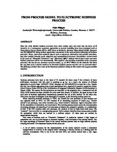
At the BPMN level, the processes are focused on the composition of services in a business driven-fashion, i.e., the orchestration process, and in that sense the business services become process activities. Moreover, the processes become composite business services that orchestrates other services and the business service networks are modeled as BPMN collaborations. A collaboration refers to the interactions between a collection of participants which represent the business entities or roles. They form a business service network and define the business process logic of each partner pertaining to a domain being modeled. The BPMN refers to a service orchestration as a participant’s private process. Consider, the wellknown BPMN dealing network example [2] depicted in Figure 1. In this business service network, a retailer provides an ordering service to a customer partner. In order to provide this service, the retailer establishes business links with other partners (e.g., scheduler, invoicer, and a shipper), and orchestrates
Shipper
Scheduling
Invoice
inria-00597070, version 1 - 15 Jun 2011
SOC those processes are mapped into models that describe services in a uniform and technology-independent way. At this lower abstraction level, i.e., the IT level, they describe the configuration of the so-called SCA assembly models which are organized in a SOA. The SCA assemblies modularize and compose service-enabled business functions in a manner that is decoupled from their application code. The SCA provides an Architecture Description Language (ADL) that offers means to define platform independent component kit architectures and a path from the business goals to the program code (e.g., executable process languages). With a graphical notation support, it describes composites of components, their connections and other related artifacts which specify how the component functions are externally consumed and/or offered. The SOC extends the Component Based Development paradigm which states that applications expose their functionality as services in a uniform and technology-independent way such that they can be provided and invoked over looselycoupled architectures. Consequently, the service-enabled business functions can be implemented as components with remotely published interfaces in a network. Our previous work has introduced a MDE approach for the automated generation of (target) canonical SCA assembly models from (source) core BPMN collaboration models, and specified relations among their metamodels as conceptual mappings [ 4]. In our semantics, models are conform to a metamodel. As a part of this view, the models are viewed as assorted collections of typed objects with attributes, and typed links among the objects. The mapping between the heterogeneous BPMN and SCA models are viewed as rules that establish relations between the model types. We refer to the program executions that implement conceptual mappings as transformations. Figure 1 depicts an example of a model transformation which will be used through the reminder of this paper. It illustrates few situations that occur when the “task-driven process logic” has to be transformed into the “component composition logic”. In the next section, we present the syntax of those models.
StartEvent EndEvent SendTask ReceiveTask Conversation
Fig. 1.
SequenceFlow
Process
Participant
Fork/Join Parallel ConversationLink Gateway
SCA Assembly Graphical Constructs Promotion Composite Component Implementation Service or Reference Callback Reference
Service
Wire
BPMN-to-SCA transformation example and languages constructs.
their exposed services: scheduling, invoicing, and shipping. To sustain the separation of concerns in the service “orchestration logic” [8], the retailer participant’s private process is modeled with different sub-roles (e.g., order, schedule, invoice and shipment). Those roles contain tasks which invoke or provide operations for a single external service provider (i.e., relative
to the retailer). The collaboration specifies the behavioral and architectural views of the business structures and their participant roles. The business links between participants are modeled as conversations that capture the service contracts. Formally, we define those models as below.
inria-00597070, version 1 - 15 Jun 2011
Definition 1 (Source Core BPMN Collaboration Model): A source core BPMN collaboration model is a tuple s = (P, R, A, A� , A� , E, F , conv, H, L) where P is a set of participants which can be partitioned to disjoint sets of sub-roles R and interaction tasks A which can be partitioned into disjoint sets of send tasks A � , receive tasks A� , E ⊆ P × P is a participant association relation, F ⊆ A × A is the sequence flow relation between the tasks, conv : ∪p∈P Ap → ∪p∈P Ap is an injective function which maps interaction tasks, H = {(a, a � ) ∈ Ap × Ap� | ∃p,p� ∈P conv(a) = a� } is the conversation relation, and L ⊆ R × A is a process relation. Likewise, when mapped to the SCA space, the services become components. The processes are executed by servicecomponents that contain the effective implementation artifacts. The inter-component interactions are conceptually similar to the inter-process invocations. Consequently, the conversations between processes can map to the connectors between components. It must to be noticed, that we intentionally hide definition of the rest of BPMN constructs shown in Figure 1 (e.g., events, sequence flows and gateways), since those types have not conceptually equivalent counterpart types in SCA as explained in Section II-B. In order to generate sound component compositions we have introduced in [ 4] a technique that emphasizes the separation of service modeling concerns between the BPMN design space and the SCA level. This technique, which we called orchestration process partitioning, is intended for avoiding the straight mapping of the inter-task dependencies to the component connectors. As shown in Figure 1, it transforms the inter-task control flow of a single orchestration process with different roles, e.g., retailer, into a new collaboration between separated processes, with singular roles. Also, it decomposes monolithic “taskdriven logic” into functionally equivalent decoupled logics. Each resulting participant, e.g., order, schedule, invoice and shipment, contains its own private process with additional synchronization tasks. Due to the lack of space, we do not give details of the partitioning algorithm. Those processes directly interact with each other with additional conversation. Formally, for any p ∈ P, the subset of interaction tasks A p that have conversations with the same external participant (i.e., service denoted p �� ∈ P) is denoted Ap��p�� = {a ∈ A�p ∪ A�p | ∃a�� ∈ Ap�� aHa�� }. By applying the orchestration partitioning algorithm to its process, i.e., denoted L p ⊆ Rp × Ap , we obtain a set of participants P � where P � = Rp and ∀p� ∈P � | ∃p�� ∈P Ap� = Ap��p�� ∧ Rp� = {p� }. Each obtained participant, i.e., “process partition” denoted p � , includes only a subset of the tasks that invoke (resp., provide) operations on a same service provider, i.e. denoted p �� (resp., consumer). Those partitions represent
“proxy” orchestrations that are related to each external service. They are fine-grained internal services composing the initial service (i.e., relative to the initial participant p) and they are matched up with p through participant associations, i.e., E ⊆ ∪p∈P × ∪p� ∈P � . In this case, we refer to the initial participant as an associated participant. The orchestration partitioning ensures a more manageable component architecture and adds a clear architectural view about how fine-grained services are composed, that the BPMN per se fails to capture. In the SCA, the assembly models logically modularize and compose components in a manner that is decoupled from their code. A component can be a composite (i.e., an assembly of components glued together using some “composition logic”) or atomic when it is considered without its inside structure. The components expose their provided ports, i.e., called services, and require (i.e., or discover) other services by means of references. They are configured to interact with the other components through the connectors, i.e., called wires. Also, the callbacks can be defined for services and references when the components play per se both the service consumer and provider roles. Finally, each component contains the implementation with an appropriate technology of the process specified by the mapped participant’s orchestration. We define those models to be used for the further formal foundations of the model transformation which are given in the next section. Definition 2 (Target Canonical SCA Assembly Model): A target canonical SCA assembly model, i.e., assimilated to a composite, is a tuple t = (B, M, N , C, O, Q, K, G, J , I, R, V, W) where B is a set of sub-composites which can be partitioned to disjoint sets of composite services M and composite references N , C is a set of components which can be partitioned into disjoint sets of component services O and component references Q, K is a set of callbacks, G ⊆ (M ∪ N ) × K is the composite callback relation, J ⊆ (O ∪ Q) × K is the component callback relation, I is the of implementations, R ⊆ (M × O) ∪ (N × Q) is the promotion relation, V ⊆ C × B is the implementation as composite relation, and W ⊆ (M ∪ Q) × (N ∪ O) is the wire relation. B. The BPMN to SCA Conceptual Mapping Before we delve into the formal details, a look at the general model transformation problem is needed. Given two metamodels S and T , the model-to-model transformation, denoted transmap : S → T , is a partial function that takes a source model s in S and produces a target model t in T . The source-to-target types correspondences are defined by a partial function, denoted map, which is based on the semantics of the source core BPMN collaboration and the target SCA assembly types. This means that only the source model objects with types that has proper conceptual mapping into target types are transformed. For example, only the tasks that specify service interactions (i.e., send or receive) are transformed. The other constructs such as gateways and events are not relevant for sketching the component assembly, but,
inria-00597070, version 1 - 15 Jun 2011
define functional aspects of the component implementation. Moreover, we define an index function as follows: ∀ p,p� ∈P | � ∃a∈Ap ,a� ∈Ap� , aHa� , index(a) = initialp if �a�� ∈Ap | a�� ∈ � prev ∗ (a) and index(a) = f inal p if �a�� ∈Ap | a�� ∈ next∗ (a). This function is used to differentiate the tasks in the service interaction patterns [9] in the following definition. The functions denoted prev ∗ (a) = {a� ∈ Ap | a� Fp∗ a} and next∗ (a) = {a� ∈ Ap | aFp∗ a� } give the set of all direct and transitive predecessors and successors of a task a, where Fp∗ is the reflexive transitive closure of F p . A static analysis of the process flow is considered to distinguish tasks in conversations. We formally define the mapping below. Definition 3 (Collaboration to Composite Mapping): Let s = (A, R, P, A� , A� , E, F , conv, H, L) be a well-formed and well-behaved source core BPMN collaboration model (i.e., given in Definition 1). s can be conceptually mapped to onto a target canonical SCA assembly model, i.e., assimilated to a composite map(s) =�(B, M, N , C, O, Q, K, G, J , I, U, V, W) where � • B = p∈P {p | ∃p� ∈P pEp }, i.e., associated participant to composite, � � � • M = p∈P {a ∈ Ap | ∃p� ,p�� ∈P pEp ∧ index(a) = p�� initial� }, i.e., initial receive task to composite service, � � • N = p∈P {a ∈ Ap | ∃p� ,p�� ∈P pEp ∧ index(a) = �� initialp },�i.e., initial send task to composite reference, � � • C = P \ p∈P {p | ∃p ∈P pEp }, i.e., participant to component, � � � • O = p∈P {a ∈ Ap | �p� ∈P pEp ∧ ∃p�� ∈P index(a) = p�� initial }, i.e., initial receive task to component service, � � � • Q = p∈P {a ∈ Ap | �p� ∈P pEp ∧ ∃p�� ∈P index(a) = p�� initial }, i.e., initial send task to component reference,� � � ∗ � • K = p∈P {a ∈ Ap ∪ Ap | ∃p� ∈P,a� ∈Ap a ∈ next (a ) ∧ � � index(a� ) = initialp ∧ index(a) = f inalp }, i.e., final receive�task or final send task to callback, � � � � • G = p∈P {(a, a ) ∈ Ap × Ap | ∃p� ,p�� ∈P pEp ∧ ∗ � p�� � a ∈ prev (a ) ∧ index(a) = initial ∧ index(a ) = �� f inalp }, i.e., associated receive task relation to composite�callback relation, � � � � • J = p∈P {(a, a ) ∈ Ap × Ap | �p� ∈P pEp ∧ ∃p�� ∈P �� a ∈ prev ∗ (a� ) ∧ index(a) = initialp ∧ index(a� ) = �� f inalp }, i.e., associated send task relation to component callback relation, � � � • I = p∈P {p | �p ∈P pEp ∧ ∃a∈Ap ,r∈Rp rLa}, i.e., process � to implementation, � � � � � • U = p∈P {(a, a ) ∈ (Ap × Ap� )∪(Ap × Ap� ) | ∃p� ,p�� ∈P �� � p�� � pEp ∧ index(a) = initial ∧ index(a ) = initialp }, i.e., associated task relation to promotion relation, � � • V = {(p, p ) ∈ P × P | ∃p� ∈P pEp� }, i.e., particip∈P pant association to implementation as composite, � � • W = {(a, a ) ∈ A�p × A�p� | ∃p� ∈P index(a) = p∈P p� initial ∧ index(a� ) = initialp ∧ aHa� }, i.e., conversation to wire.
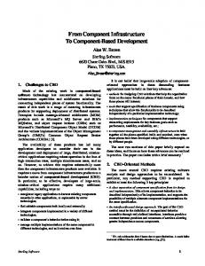
Note that we assume the well-formedness of the source models and its well behavedeness. It means they are consistent with the structural and the behavioral requirements of service interaction specification, e.g., defined in [9]. For the minimal correctness requirements on the structure of the processes we follow [10], e.g., there is a single start event, there is one or more end events, and every process task is on a path from the start event to an end event. Due to lack of space, we refer to [11] for detailed structural requirements on the SCA models. Since the BPNM participants map into SCA components, then, after the orchestration partitioning, the obtained participant associations between the new participants map into the implementations as composites. For example, Figure 1 shows the mapping of participants resulting from the retailer’s process partitioning. The associated participant is mapped to a component. The collaboration obtained after the partitioning maps into the retailer composite which is attached to the implementation of the initial retailer component. Recursively, each obtained sub-participant, e.g., order, schedule, invoice and shipment, is mapped onto a component, and it is placed within the implementing composite. The process of each subparticipant maps to a single component implementation. This allows different technologies to be used for each process implementation. It has to be noticed that we do not make recommendations on the technology usage. III. BPMN TO SCA M ODEL T RANSFORMATION In the previous section, we have introduced the conceptual mapping for the transformation of canonical SCA assembly models from core BPMN collaboration models. This section performs a more through investigation on the implementation of the transformation code. In order to implement the transformation of the model artifacts, we use the ATL transformation chain which is depicted in Figure 2. The ATL is integrated in the Eclipse development environment and can handle models based on the core Eclipse Modeling Framework (Ecore [ 6]). It also provides support for models using EMF-based UML profiles. In our proof-of-concept prototype, the BPMN and SCA metamodels are created using the Ecore. The BPMN diagrams and the SCA definitions metamodels are specified in the eXtensible Markup Language Metadata Interchange (XMI). Transformation Chain Ecore BPMN Metamodel Source Model BPMN XMI File
Partitionned Model
Orchestration Partitioning
Simplified BPMN Metamodel * * Collaboration Definition * Participant SendTask ReceiveTask 0..1
Process
Fig. 2.
*
FlowElement
Legend: Conforms To Transformed In
SCA Metamodel
Target Model SCA XMI Files
BPMN-To-SCA
Simplified SCA Metamodel Composite * * Component
*
ComponentService
ComponentReference
BPMN-to-SCA transformation ATL chain overview.
Rather than using intermediate model facilities [12], we
inria-00597070, version 1 - 15 Jun 2011
advocate a direct transformation chain that starts off from a BPMN XMI file containing the source core BPMN collaboration model. Then, its orchestrations are partitioned. Subsequently, this model is transformed into a target canonical SCA assembly model resulting in XML files which contain the Service Component Definition Language (SCDL [3]) of the mapped composites, i.e., the particular ADL of the SCA. An ATL-code is composed of rules describing how to generate the objects of the target models. It is compiled into the ATL bytecode and then executed by the ATL virtual machine [ 5]. As a simple running example, consider the following BPMNtoSCA ATL program, i.e., the module. module BPMNtoSCA; create OUT : SCA from IN : BPMN; helper context BPMN!Definitions def : CollaborationHasParticipants() : Boolean = if (self.getCollaboration(). participants.oclIsUndefined()) then false else true endif; helper context BPMN!Definitions def : getDefinitions() : BPMN!Definitions = self; helper context BPMN!Definitions def : getCollaboration() : BPMN!Collaboration = (self.rootElements -> select (e | e.oclIsTypeOf( BPMN!Collaboration))).asSequence().first(); rule CollaborationtoComposite { from d: BPMN!Definitions, s: BPMN!Collaboration to t: SCA!Composite(name collect(e | thisModule.ReceiveTaskToService(e)))} lazy rule SendTaskToReference { from sen: BPMN!SendTask to ref: SCA!ComponentReference(name