From CAD to geons : a simplified data representation for rapid indexing of large CAD models database Normand Grégoirea∗ , Richard Lepagea, Tanneguy Redarceb a
Laboratoire d'Imagerie, de Vision et d'Intelligence Artificielle, École de Technologie Supérieure, Montreal, Quebec H3C 1K3, Canada b
Laboratoire d'Automatique Industrielle, Institut National des Sciences Appliquées, Villeurbanne 69621, France ABSTRACT Automated inspection of manufactured parts is a challenging problem and a crucial issue for any production process. When concerned with dimensional tolerancing, CAD models are a highly desirable reference, as they describe precisely the parts under inspection. However, the time needed to identify the right model in a large CAD database is far too long for on-line inspection because of the huge amount of data to be analyzed. In this paper, we propose to use a vision-based representation for the parts which is much less accurate than CAD descriptions, but offers very low storage requirements, thus speeding up the identification stage. We discuss the inspection system proposed and report our preliminary results in converting CAD models to their simplified representation. Keywords: Automated visual inspection, geons, form feature recognition
1. INTRODUCTION Since a decade, the problem of on-line automated inspection has gained increasing attention from computer vision researchers. While fabrication and assembly are now strongly automated in computer integrated manufacturing environments, dimensional inspection has always stayed a step behind. Some difficulties in automating this part of the process involve robustness, speed and accuracy. The need for an accurate description of objects has brought practitioners to use CAD models as reference for many inspection systems. When the part under inspection is unknown, the sensed data is typically processed to yield higher level descriptions, used in the matching stage against indexes derived from the CAD database. These indexes can be based directly on the geometry and topology of objects, for instance edge types and dimensions, relationship between faces, etc., or be more complex features, such as shape descriptors, etc. The choice of indexes for a specific system is strongly related to the type of input data, which in turn depends on the inspection needs : validating the outline of objects can be done with intensity images, so that indexes will likely be edge-based, while checking for surface defects requires 3D images, and suggests surface-based representations. 1.1 Recognition By Components In this project, we propose to use geons for indexing the database, and more generally for identifying the inspected objects. Geons were introduced by Biederman1 in his theory of Recognition By Components (RBC), where he tried to explain how a scene is analyzed at first glance by the human visual system. As the name implies, RBC posits that we mentally split the objects in our field of view into their natural components, namely geons ; this coarse assembly of primitive volumes would then be used for early identification. This simple and attractive concept has led some vision researchers to further investigate the usability of RBC in the context of 3D object recognition2-3. Even if geons could have any 3D shape, they are usually restricted for convenience to generalized cylinders (GC), which still allow to describe a large number of objects, natural or manufactured. *
Correspondence : e-mail:
[email protected] ; tel: (514) 396-8800, # 7674 ; fax: (514) 396-8595
224
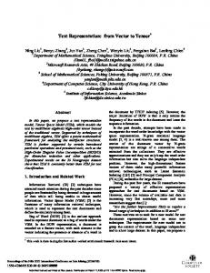
curved reflective SYMMETRY asymmetric
increasing and decreasing
AXIS straight constant
reflective and rotational straight EDGES
DIMENSION increasing
curved
Fig. 1. Original geon attributes.
As shown in Fig. 1, Biederman defined originally four qualitative attributes to classify a geon, based on the characteristics of the axis and the cross-section of the GC. A complete object will be represented with a structural graph, where each node corresponds to one of its geons, and where the arcs between the nodes indicate adjacency of geons. Geon-based representation has the advantage of being invariant to scale, rotation and translation. Since geons are qualitative entities, they are mostly aimed to describe families of objects, rather than a specific one. This is a weakness of the geon approach, as it can't be used alone for discriminating objects that would only differ in scale, and thus share the very same qualitative description. If a generic description is too vague for any task that requires some accuracy, such as metrology, it could be well suited on the other hand as an indexing key in a large database. As a matter of fact, Biederman calculates that more than 154 million qualitative different objects can be derived from all combinations possible of three geons.
2. INSPECTION SYSTEM PROPOSED A simplified block diagram of our inspection system is shown in Fig. 2. Its distinctive feature over other inspection systems is that it uses two different sensors, that is a conventionnal CCD camera and a laser range finder ; the former is used solely for identification purposes, while the latter is needed to get accurate 3D points of objects. A monocular intensity image of the object is first input to an image processing module, that will try to identify as much geons as possible. Since the object is viewed under a single observation angle, it is unlikely that all geons will always be visible ; however, as suggested by RBC, the key idea is to properly identify a few geons, assuming the viewing angle is not degenerate. In such a case, more than one view would be needed to get a better knowledge of the object. The geons found in the image are next fed to the matching module, with their connectivity. This module then proceeds to find the best match between that description and all models stored in the database using geons as search index. Considering that some geons previously identified might actually be wrong due to a erroneous computation of their attributes, and that some other geons could be missing, matching should be based on a pattern recognition strategy able to find the closest description available in the database. We currently work on neural networks as indexing mechanism, for their robustness to incomplete or noisy input, and their processing speed. When the object is identified, a mobile active range finder scans its surfaces under the control of an acquisition module. The aim of this module is twofold : first, to scan the object completely (except maybe for its bottom surface) and second, to scan it evenly. The whole scan path cannot always be the same if we want to inspect as much faces of an object as possible ; however, since the part under inspection is supposed to be known at this stage, it should be feasible to automatically compute a scan path optimized for this object. The acquisition control module will then check that as many faces as possible are scanned, and keep the laser beam perpendicular to each surface. Once the object has been scanned and its CAD reference is known, the system can finally proceed to inspection, which is done through registration between 3D points and the CAD description, as explained in Boulanger et al.4. The inspection module will retrieve the CAD description in the database from an index provided by the matching module.
225
2D geon extraction
matching
geon descriptions
2D
database
3D object
acquisition control
inspection
3D geon extraction
CAD descriptions
action
CAD model
Fig. 2. Overview of the inspection system.
The database of models is built off-line, and stores each model in two different ways : first, as a conventional CAD description used only in the inspection process, and second as a geon description used for identifying the object. One of these is an accurate description of the object, while the other is its coarse representation. Although it may look as describing twice every model would increase much the size of the database, this is not the case as the size of a geon description is far smaller than any CAD description. A last module is needed to convert CAD models to geon descriptions ; this module will be discussed next, along with some adjustments made to RBC so to use it with the class of manufactured objects aimed by this project.
3. EXTRACTING GEONS FROM CAD MODELS 3.1 Adjustments to RBC As mentionned before, RBC was primarly intended to explain some mechanisms of human vision ; it assumes that objects in a scene are made of well defined geons, which is not always the case for real-world industrial parts. One of the first problem encountered when trying to describe manufactured objects with a geon approach is the presence of holes and depressions, that are not accounted for in RBC since all geons are presumed to be solid. However, these entities are common in manufacturing, and represent an important key for discriminating objects. A first hand solution for describing holes would be to define them implicitely, by their surrounding geons ; however, trying to define an immaterial entity only with solid bodies often leads to unpractical solutions, and most important, doesn't provide a ready-to-use indexing key since the entity is still hidden in the description. For the purpose of this project, we added a new attribute indicating the material type of a geon, so that solid and hollow volumes of an object are respectively called positive and negative geons. Introducing this class of immaterial geons is new to the domain : negative geons were never considered formally by geonicists, even though the search for negative features has solid grounds in mechanical engineering. The type of objects usually recognized with geon-based approaches explain why this concept of negative features never passed from one field to the other. Our experiments also showed that the edge type attribute as defined by Biederman is too restrictive for describing some industrial parts. As illustrated in Fig. 3, using only straight and curved edge types for qualifying the generating edges of a GC would sometimes result with an oversegmentation of the object. For the case shown, three geons are found under this edge type constraint, while the whole object is indeed made of a single GC. We used a third attribute value to avoid that kind of degeneracy, that is an hybrid edge type, which simply indicates a combination of straight and curved generating edges. This new attribute value has a practical justification for the inspection system, since an image analysis program will more likely find one GC rather than three GC's in a real intensity image of this object.
226
Fig. 3.
Oversegmentation of an object due to a restrictive edge type attribute.
We also simplified the dimension attribute that indicates the behaviour of the sweep function. As pointed out by Bergevin3, a geon of increasing and decreasing cross-sectional size can be interpreted as two single geons of increasing size joined at their ends. This attribute value is of weak practical interest when the objects are modeled with regular primitives (planes, cylinders, cones, etc., as opposed to NURBS), since the joining edge of the two geons will always be present on the image, if this part of the object is visible. We then consider only two values for the dimension attribute, that is constant or variable dimension. The codification of connectivity as suggested in RBC was typical of human perception with values such as above, below, etc., and loosely defined, its main concern being to locate two connected geons in common terms. We had to reject this scheme as did most, if not all, of our predecessors in the field. We propose to codify connectivity relatively to the connecting faces of the geons : if T stands for a terminal face and L for a lateral face of a geon, respectively an ending face and a side face of the GC, then there would be three basic types of connection, namely TT, LL and TL, as shown in Fig. 4.
TT
TL
LL
X
Fig. 4. Connectivity values based on the connecting faces of the geons. This tagging scheme is insensitive to the angle between the sweep axis of the geons, even if those shown are parallel or perpendicular.
A common approach in the field is to use the relative position of the sweep axis of the geons to qualify their connectivity. Although the axis is a natural reference for locating geons, it also involves a high computational cost in image analysis when geons are skewed. Our proposal has the advantage of a greater simplicity, without however being totally fool-proof in its actual form : if for instance the case marked X in Fig. 4 could be tagged as a TT junction for a hole in a block, this generalization is less obvious when talking about a blind hole. Some other configurations of geons might as well be of type TTL or TLL, for instance if a geon connects right on an edge of its neighbour. 3.2 General steps for extracting geons The process for analyzing CAD data in search of geons is much like form feature recognition, which is studied since more than a decade in the context of Computer Assisted Process Planning (CAPP). As most of the previous work in that domain, we start from B-rep data, which describes an object as an assembly of faces with their specific attributes, and that are bounded by sequences of edges called loops. Converting such a description into a geon-based representation is actually an attempt to add a family of volumetric primitives to the conventional description. Although a Constructive Solid Geometry (CSG) scheme might appear at first glance as a better choice for input data, we preferred traditional B-rep for its widespread availability in industrial environments. The algorithm is based on an hypothesize-and-test strategy, and involves the following steps : 1. 2.
3.
4.
5.
Build first an appropriate data structure from the CAD description of the model. We use the so-called half-edge data structure which has proven to be valuable for CAD analysis5. Look for a potential geon among the data. This is where the computer activates hypotheses of geons, guided on geometric or topologic clues. Merely exploring neighbours of a randomly chosen first face would have a high computational cost for the variety of geometries that can occur, and is very difficult to analyze since the volume is not known yet. Explore around the entities that activated the initial hypothesis in order to extract all possible faces and edges that could belong to the geon. This search is mostly heuristic-driven as it is extremely difficult to devise a set of constraints that can deal with any possible case. Compute the attributes of the geon. The primary goal of this stage is actually to confirm the hypothesis, which is done by identifying the geon itself. If this process fails, most likely because the hypothesis was not properly built, then whether refine the hypothesis and continue at step 3, or reject it and go back to step 2. If the hypothesis was confirmed, memorize the geon and its descendants, and remove them from the model. This last operation is done to progressively reduce the complexity and size of the remaining data.
227
6.
7. 8.
9.
Complete the model. Removing recognized entities from the model produce many temporary inconsistencies such as unbounded edges, open loops, etc., so that a completion step is needed to recover geometric consistency, by adding new faces, closing loops, and so on. From a more general point of view, the completion step corresponds to an evolution of the model toward a simpler form. Return to step 2 as long as there are entities left. Otherwise, validate the individual geons, that is check if some of them are not part of a larger one. A drawback of a local analysis is that it won't recognize a large geon split into separate volumes, which requires then some global analysis to take place after. Compute the connectivity of the geons, and write the geon description in the database.
3.3 Methodology A CAD description is basically an enumeration of faces, edges and vertices that should be searched and analyzed methodically ; because of the huge amount of particular cases found in manufactured objects, we need to devise a global strategy able to identify geons at a reasonable computational cost. At the highest level, analysis will rely on the faces of the model as these entities are just under the volumes in the hierarchy of primitives. The general principle is to pair the good faces together, so that they fit one of the 72 geons defined by our set of attributes. Lower entities, e.g. edges and vertices, will be mostly used to reduce the complexity of geometrical computations since they represent the critical points of the faces, but in a lower dimension. Among the possible strategies, template matching would be a highly ineffective and costly method as it would require to search for each of the 72 geons, whether in the geometrical domain or in another one, such as graphs or syntactic chains. Apart from the important number of primitives to codify and search for, this method would often fail, because the assembly of several geons modifies or eliminates many shared entities that actually define the primitive. Previous works in form feature recognition clearly showed the difficulty of codifying the sufficient conditions of existence of a primitive juxtaposed to other ones6-7. At this point, we feel that the only primitive that can be searched for in the data is the generalized cylinder, which is the smallest common denominator between all geons. Hypotheses will be activated if there is some confidence to find a GC at a given location of the model, and will be confirmed later on if the selected entities satisfy the constraints of a GC. Among the different entities that define a GC, the generating loop and face are probably the safest to use to activate an hypothesis, as they define the startpoint of a geon ; neighbouring faces or edges can then be explored and eventually be added to the hypothesis if they fit some criteria. Similarly to most of the previous work with GC's, we assume our GC's to be homogeneous, that is to have a constant shape along the sweep axis. This assumption excludes sculptured surfaces in the model. We implemented so far one method of analysis, based on the inner loops found in the model. Inner loops are sequences of edges located on a single face, inside of its outer boundary. We observe for the object of Fig. 5 that inner loops are the place where a supporting geon will meet with one or more supported geons, positive if they are protrusions or connectors, and negative in the case of holes or depressions. This method is somewhat similar to the one proposed by Gavankar and Henderson8, where the object was first converted to a surface graph, and then scanned for cut-vertices, i.e. nodes that would split the graph in two distinctive parts if removed ; such nodes correspond indeed to the faces that have inner loops. The main difference with our approach is that we operate directly in the geometrical domain instead of the graph domain. It should be clear that our proposition is not intended to extract all geons of an object, nor that it would find any geon in a given model. Even though this algorithm adresses only one geometric situation, it is worthwhile to implement as protrusions and depressions are very common features of manufactured objects. Fig. 5. Inner loops (in bold) of an object.
228
4. RESULTS AND DISCUSSION Loops are readily available in a B-rep description since the spatial extent of a surface is a necessary information for any solid modeler. However, there usually won't be anything in the data that will identify the inner loops, as opposed to the outer loops. Since all surfaces have an outer loop of edges to prevent them from extending to infinity, inner loops can only belong to faces that have more than one loop. One should not conclude at this point that if the outer loop of a face is identified, all of its other loops are necessarily the inner ones : for instance, two disjoint faces lying on the same infinite plane will often be represented as a single face with two (outer) loops. Even though this kind of representation scheme is inconsistent to common sense, where distinct physical faces should be assigned distinct identities, it is totally correct in a mathematical sense. So the main idea is to look for the faces that have more than one loop, and then check which of these loops are the inner ones, if any ; each inner loop found should then activate a new hypothesis of geon. As inner loops are contained inside their outer loop, we identify inner loops with an inclusion test performed between each pair of loops of a face, and memorize the results in what we called the inclusion matrix. Cross-checks between columns and lines of the inclusion matrix will indicate which loops are which, and will reveal eventual cases of doubly included loops, which would make of the innermost loop an outer one. As most inclusion test algorithms are designed for 2D analysis of point sets, we analyze the relative position of loops in their parametric space (u, v) instead of the 3D space (x, y, z), which avoids projections of non-planar faces onto a reference plane. Fig. 6 illustrates a few cases of the inclusion matrix, along with a simplified view of the loops each one represents. C
A
A A
B
C B
B
A
B
C
A
0
0
0
B
0
0
C
1
0
A
C
A
B
C
A
0
1
1
0
B
0
0
0
C
0
0
B
C
A
B
C
A
B
C
A
0
0
0
A
0
1
1
0
B
0
0
0
B
0
0
0
0
C
0
0
0
C
0
1
0
Fig. 6. Inclusion matrices.
As mentionned earlier, the procedure will explore around each inner loop found in order to extract the faces likely to belong to the geon. An obvious heuristic is to include any face whose outer loop has a common edge with the inner loop. If this rule of thumb is true most of times, there are objects for which some neighbouring faces connected to the inner loop are not part of the hypothetic geon. It should be noted also that some hypotheses might appear twice, for instance in the case of passages : as shown for the object of Fig. 7, a passage is a through hole that is usually bounded at each end by an inner loop. Since both loops will activate a distinct hypothesis for the same geon, the algorithm should reject one of them.
(a)
(b)
(c)
Fig. 7. Example results. (a) Original object. (b) Geons found (in bold) with inner loops. (c) Remaining data.
229
This algorithm is a root-last process, where the supported geons are progressively removed from the initial object as they are recognized, with the supporting geon being left for the end. This approach contrasts with root-first algorithms, where the computer needs to known beforehand the stock's size and shape, and then proceeds to feature recognition by a subtractive principle. In our case, nothing else than the CAD description of the actual object is provided to the system. Another interesting point of using inner loops for searching GC's is that this method is likely to retrieve geons of any shape, no matter the shape's complexity. For instance, a template matching approach would hardly find the passage in the long arm of the object of Fig. 7 (a), unless the computer would have been programmed to look for that specific shape. Our approach has the advantage of searching for only one generic primitive, whose instantiation is classified afterwards. Once the extraction phase is over, the hypothesis is tested by computing the attributes of the geon, with the inner loop presumed to be its the generating loop. This assumption is generally true, but has to be reconsidered sometimes, such as for the object of Fig. 7. In this case, the small arm connects to the large cylinder through an inner loop, that is not however the generating loop of the arm. The edge type attribute is evaluated by direct inspection of the edges of the inner loop, while the materiality of the geon can be determined by computing the convexity of the same edges with a triple product :
(n* 1
*
× n2 )
⋅ V* 00
⇒ convex edge ⇒ concave edge
(1)
where V is the edge vector oriented toward the positive path of the edge, and n1 and n2 are the normals to the surfaces for which the edge is respectively forward and backward oriented. It could be proved that an inner loop of strictly convex edges defines a negative geon, while the same loop will define a positive geon if all of its edges are concave. Axis curvature can be determined by inspecting the lateral edges of the geon, which are the edges that join the two ending loops of the geon. These loops are necessarily part of a valid hypothesis, as one is the activating condition and the other one the terminating condition of the hypothesis. Axis curvature is similar to the curvature of the lateral edges. Similarly, the dimension attribute of the geon is computed by comparing its two end loops. Since our domain is constrained to regular primitives, the sweep function can only be constant, or monotonically increasing or decreasing. That property avoids checking the dimension of the cross-sectional size all along the sweep axis. Computing the symmetry of the generating loops requires a little bit more calculation. We proceed by finding all possible symmetry axes, which by definition can only pass through the center of gravity of the generating loop, and then check if this loop is indeed symmetrical relative to one of theses axes. A problem that can occur is when the inner loop joins a group of geons with the supporting geon, as illustrated in Fig. 8. In this case, the algorithm is unlikely to correctly identify any geon, since they share some common faces that should be split prior to identification. Our program will then cut the model on the inner loop, thus separating the supporting and supported geons. Even though no geon is recognized at this stage, this procedure will simplify further analysis, since the initial object is now made of two simpler objects. This is an obvious breath-first search strategy, where the main problem is reduced to smaller subproblems when no immediate solution can be found. Hybrid loops are another particular case that is worth mentionning. Less frequent with manufactured objects, these are inner loops made of both convex and concave edges. Like the case discussed before, these loops join a supporting geon with a group of supported geons, some of them being positive geons, and some other being negative geons. This kind of loop cannot be taken as a whole, but has to be analyzed locally. Fig. 8. Inner loop that joins a group of supported geons with a supporting geon.
230
5. CONCLUSIONS We have presented in this paper geons as a possible indexing key for a CAD database, and proposed an inspection system where it could be used. We didn't emphasized on the inspection system, as it is still being researched and that no global results are available yet. We've shown a possible strategy for extracting geons from a CAD model based on inner loops. This method is not intended to extract all geons of a given model ; however, it is likely to find many geons, since inner loops are a common feature with manufactured objects.
REFERENCES 1. 2. 3. 4.
5. 6. 7. 8.
I. Biederman, “Recognition by components : a theory of human image understanding”, Psychological Review, 94, pp. 115-147, 1987. S. Dickinson, A. Pentland and A. Rosenfeld, “3D shape recovery using distributed aspect matching”, IEEE Trans. on Pattern Analysis and Machine Intelligence, 14(2), pp. 174-198, 1992. R. Bergevin and M. Levine, “Generic object recognition : Building and matching coarse descriptions from line drawings”, IEEE Trans. on Pattern Analysis and Machine Intelligence, 15(1), pp. 19-36, 1993. P. Boulanger, V, Moron, and H. T. Redarce, “High-speed and non-contact validation of rapid prototyping parts”, SPIE's Int. Symp. on Intelligent Systems and Advanced Manufacturing. : Rapid Product Development Technologies, SPIE vol. 2910, pp. 46-60, 1996. J. Shah, and M. Mäntylä, Parametric and feature-based CAD/CAM, John Wiley & Sons, New York, 1995. J. Shah, “Assessment of features technology”, Computer-Aided Design, 23(5), pp. 331-343, 1991. M. Wu, and C. Liu, “Analysis on machined feature recognition techniques based on B-rep”, Computer-Aided Design, 28(8), pp. 603-616, 1996. P. Gavankar, and M. Henderson, “Graph-based extraction of protrusions and depressions from boundary representations”, Computer-Aided Design, 22(7), pp. 442-450, 1990.
231