From Conceptual Models to Simulation Models - Semantic Scholar
Recommend Documents
Model Driven Development of Agent-Based Simulations. Takashi Iba â 1 ... become serious too much up to now, because ...... 59â68 (IOS Press). [Kleppe et al.
approach (Scheer, 2000) can be used to express business processes. ..... service (Bechtel and Jayaram, 1997, Christopher, 1998, Hewitt, 1994). Vendor ...
addition to software specifications, business models, domain models and ... The photography agency is dedicated to the management of photo reports and their.
evaporative pumping associated with the Mid. Devonian ...... stones at depth and significant cooling as the ...... systems (e.g. Sears & Lucia 1980; Simms 1984;.
undertaking research into the conceptual foundations of software engineering methods within the .... that go well beyond any âmind-freeâ external reality (Lakoff, 1988). Indeed, ..... pany to provide a trouble ticketing system (TTS). This system
learning tool for Thai dance body motion. In Design, User. Experience, and Usability. Health, Learning, Playing,. Cultural, and Cross-Cultural User Experience ...
Currently, a few hun- dred groups worldwide use the system, a number of such e orts have resulted ... FS97] M. Fowler and K. Scott. UML Destilled: Applying the ...
We show that we can effectively fit complex animation models to noisy image data .... faces and bodies to noisy image data with very limited manual intervention.
Sep 30, 1999 - women were less likely than Hindu women to adopt contraception (OR = 0.5; ... At this rate of growth, the next decade could see UP's popu-.
FROM DATA TO SIMULATION MODELS: COMPONENT-BASED. MODEL GENERATION WITH A DATA-DRIVEN APPROACH. Yilin Huang. Mamadou D. Seck.
Jul 17, 2009 - September 2008, one from MSNBC, and the other from the Australian ... the mean time lag between the MSNBC and ABC news feeds was 150.
To appear in Information Modelling and Knowledge Bases VI, IOS Press, ... standardisation and data interchange; one of the first coding/classification system ...
resources, thus allowing the belter design of altematives. Some of the ...... Sharpley, A. N.; William J. R EPIC Model Documentation USDA Tech. Bull No 1768 ...
We present an architecture for grid-enabled simulation modeling. ... MoSeS (Modelling and Simulation for e-Social Science) is a research node of the National.
Company. Car repaired. Pay repairs. Maximize estimate. Continue business. D. D. D .... rich set of semantic referential relationships, and a first-class treatment ...
of the total cost of gain in calf and yearling beef cattle finishing ... Shorthorn. 12. 26. 18. 51 are 2 publicly available biological models that can pre- dict animal ...
Oct 20, 2006 - Web Application (UWA) design methodology. UWA models are able to describe the structure of the application contents, the semantic relations ...
and presentation of MD models accomplished with the object-oriented (OO) approach presented in [5] by using a standard format. To accomplish this goal,.
Developing Web Applications from Conceptual. Models. *. Vicente Pelechano, Joan Fons, Manoli Albert, and Oscar Pastor. Departament of Information Systems ...
Oct 20, 2006 - abstracting conceptual user-centered models from existing Web applications to .... process involve the HTML client pages that the application presents to the .... making part of the Collection Center, the diagram also specifies the car
Software performance analysis often begins from scenario definitions, which ... such as service demands by responsib ilities, arrival rates at start points, ..... User: TRS customer ... Figure 5: Ticket Reservation System Use Case Map model.
campo sujo, campo cerrado, cerrado sensu stricto and cerradao [5]. The cerrado communities are related to a general ecosystem, the cerrado sensu lato.
Egon Brunswik's (1956) theoretical insights in eco- .... Brunswik (1956) noted the need for congruence .... baseball outfielders could only be distinguished from.
Feb 7, 2003 - environment where the primary buildings are of the skyscraper style. This paper presents the initial design and implementation towards a ...
From Conceptual Models to Simulation Models - Semantic Scholar
Ascape. Our Solution. (Boxed Economy). Supporting Systems for. Agent-Based Simulation. Figure 1: Level of Abstraction, Languages, and. Supporting Systems.
From Conceptual Models to Simulation Models: Model Driven Development of Agent-Based Simulations Takashi Iba †1 Yoshiaki Matsuzawa †2 Nozomu Aoyama †2 †1 Faculty of Policy Management, Keio University †2 Graduate School of Media and Governance, Keio University
1
2
Introduction
2.1
Every social issue surrounding us today stems from complex factors. Now we need to establish a trans-disciplinary approach so that we can examine the flow of interconnected phenomena. The solution lies with new methodology called agent-based modeling. This concept makes it possible to model our society as a system formed by an interaction between numbers of autonomous agents. In the current state in the study of simulating agent-based economic models, however, there is a problem that needs to be resolved. That is the absence of integrated environment to support a whole research process from conceptual modeling to simulation analysis. The problem did not become serious too much up to now, because the models were small-scale and for experimental use. It becomes, however, indispensable to resolve the existing problem, as the simulations come to be used practically in social science, policy analysis, and business field. In this paper, we propose a new development process, which we call “Model Driven Development”. To realize the process, we also propose tools that help us build the conceptual models and simulation models. Then, the simple trade model is introduced as the example in the last part of the paper.
Background Supporting Systems for Simulation Development
In the last some years, several languages, frameworks and tools for agent-based simulations have been proposed. For example, “Swarm Simulation System”, which seems to be the most famous and to be used, provides the class library for the simulation of complex adaptive systems [Minar et al., 1996]. As well as Swarm, “RePast” provides the class library to make the agent-based model [Collier, 2003]. “Ascape” also provides the framework, and it is said that the amount of the code description can be less than that of Swarm and RePast [Parker, 2001]. These support systems try to solve the problem with a necessary support to the modeler who has a little (or, no) experience of the computer programming. As the solution, those systems assist the modelers to write programs by providing a general library and framework. In fact, these systems are useful for the reduction of programming. They, however, would not support for the modelers to do conceptual modeling. We would like to emphasize that it is important to support modeling as well as to support programming. Thus, we need a new system that helps us build the conceptual models and simulation models. 1
Model Driven Development: A New Paradigm of Software Development
Figure 2: Traditional Process of Software Development
In the field of software engineering, there is a trend toward considering the design models as the development artifacts that contribute directly to software development. “MDA” (Model Driven Architecture) and “Executable UML” (Unified Modeling Language) are proposed for the Model Driven Development [Frankel, 2003, Mellor and Balcer, 2002, Kleppe et al., 2003]. The point is “using modeling languages as programming languages rather than merely as design languages.”[Frankel, 2003]. As a result, “It makes it possible to raise the level of abstraction for software development”[Frankel, 2003] (Figure 1). History tells that the productivity and quality are improved in consequence of raising the level of abstraction. The traditional development process of software models is driven by implementation, it means program coding (Figure 2). In the traditional development process, the transformation from design models to program codes is done by hand. According to the process, the modeler should write a lot of program codes. In this sense, design model is said to be “just paper” [Kleppe et al., 2003] and “blueprint” [Mellor and Balcer, 2002]. On the contrary, the emerging concept of software development process is driven by modeling (Figure 3). We can use more high-level language for development, instead of writing in the lowerlevel language. It means that a modeler describe
the models rather than program codes. Therefore, the modeler can concentrate on modeling without considering the software implementation, because the program code will be an exact translation of the design model. In this sense, the design model is no longer “just paper” and “blueprint”. In this paper, we propose process and tools for Model Driven Development of agent-based social simulations.
3 3.1
Proposed Process based on Model Driven Development Process Overview
The proposed process, which is based on Model Driven Development, consists of three major phases: “Conceptual Modeling Phase”, “Simulation Design Phase”, and “Verification Phase” (Figure 4). In the conceptual modeling phase, the modeler analyzes the target world and describes the conceptual model. He/She defines the model elements, for example agents and information, according to the conceptual model framework “Boxed Economy Foundation Model” (BEFM). The products developed in the phase are “Conceptual-Model Class Diagram”, “Activity Diagram”, and “Communication-Sequence Dia2
The purpose of conceptual modeling phase is to specify what the target system is. The modeler extracts “Agent”, “Behavior”, “Relation”, “Goods”, and “Information” from the target world, and defines them. In addition, he/she describes the activities of agents and the sequence of communications. UML (Unified Modeling Language) is used for describing the model 1 . The products developed in the phase are followings:
Conceptual Modeling
Simulation Design
Verification Iteration
Figure 4: Major Phases in Our Proposed Process
• Conceptual-Model Class Diagram • Activity Diagram • Communication-Sequence Diagram
gram”. In the simulation design phase, the modeler designs and implements the simulation model, which is executable program on the platform “Boxed Economy Simulation Platform”(BESP). The modeler translates the conceptual models into simulation models according to the software framework “Foundation Model Framework” (FMFW). The products are “SimulationModel Class Diagram”, “Statechart Diagram”, “Initial World-Settings”, and the corresponding program codes. In the verification phase, the modeler runs the simulation and inspects whether the simulation program is coded rightly. If necessary, the modeler returns to the first or second phase and modifies the models.
3.2.2
Static View
First step is to specify the characters in the target world. The specification is done based on “Boxed Economy Foundation Model” (BEFM). BEFM can be a frame of reference for recognizing the target world (Figure 5). With using the model framework, the modeler can focus on the part of the target world [Iba et al., 2002, Iba et al., 2002]. The modeler extracts the following characters from the target world, and defines types of them in the conceptual-model class diagram. 1
UML (Unified Modeling Language) is standard language for object-oriented modeling today. See the reference [Rumbaugh et al., 1999] for more details.
3
Agent An autonomous actor who does an activity is represented by Agent type. Each individual and social groups such as corporations, governments, families, schools, regional communities, and countries are described as Agents in the model.
3.2.3
Dynamic View
Next step is to describing the dynamics of the phenomena with two approaches: “Activity Analysis” and “Communication-Sequence Analysis”. By the activity analysis, the modeler describes the procedure of agent’s behaviors in an activity diagram. The activity diagram is very similar to a flowchart. By the communication-sequence analysis, the modeler describes the sequence of the communication among the agents. The agent’s behavior is often done in cooperation with the other behaviors. Thus, the modeler describes the exchange of goods / information in a communication-sequence diagram. The communication-sequence diagram can be used to understand the cooperation of behaviors.
Behavior The behavior of the agent is represented by Behavior type. Various activities such as decision-making, production, trade and communication, are described as Behavior in the model. Different Behaviors can be done at the same time by the Agent. A Behavior has an internal state, and the state can be changed by events. Relation An agent in a model usually has some kind of relationship with other agents rather than being isolated. The relation between agents is represented by Relation type. The relationships, such as friends, spouses, teachers, students, employees, employers, are described as Relation in the model. Relation is an object by which two Agents are connected in a one-way or twoways direction.
3.2.4
Iteration
Now the modeler has finished the first iteration of conceptual modeling phase, but there is an unfinished task. The rest task is to define the goods and information. Since the modeler ought to describe the communication-sequence diagram, it is easy to know what types of goods and information should be defined.
Goods A material/immaterial thing, which is possessed by Agents, is represented by Goods type. For example, automobiles, oil, corn, financial stocks, right of land, books, advertisements, memorandums, water, voices, noises, garbage, and money are described as Goods in the model. Goods often hold Information describing various contents, which we will explain next.
3.3 3.3.1
Simulation Design Phase Purpose and Products
The purpose of simulation design phase is to translate the conceptual models into the simulation models (programs). The modeler makes the simulation model based on the software framework “Foundation Model Framework”(FMFW). FMFW is a concrete software framework of the model framework “BEFM”(Figure 6). UML is also used for describing the model. The products developed in the phase are followings:
Information Information which is held by Goods or Agents is represented by Information type. Information will never exist alone, and will always be held by Goods or Agents. For example, a newspaper can be modeled as an object that the newspaper article (as Information) is printed on paper (as Goods). And a conversation can be modeled as a combination of the contents (as Information) and the voice (as immaterial and transient Goods). Examples of information possessed by Agents are “memory”, “genetic information”, and “name”.
The candidate of the action is the activity in the activity diagram. Then, the modeler may implement the details of the simulation as a program code 2 . The phase is supported a lot by our tools, which we will discuss in the next section. In the phase, the modeler writes the following program codes if necessary:
Modeling Process Conceptual Modeling
Model Framework "Boxed Economy Foundation Model"
Conceptual Model
ऴإӓᨼƠƯȓȇǪȆȸȗ ȬdzȸȀȸǛទλƢǔ
Information *
Relation * Ტ᧙̞Უ *
start
Space
World
Ტᆰ᧓Უ
end
Agent
ᲢǨȸǸǧȳȈᲣ *
* ᲢɭမᲣ
ෞᝲᎍ
ȓȇǪȆȸȗȬdzȸȀȸǛ̅ဇƢǔ
ᲢऴإᲣ
Entity
Ტܱ˳Უ
Goods
ᲢᝠᲣ
*
* Channel ᲢኺែᲣ *
*
̅ဇᙹǛƑǔ
Behavior
ᲢᘍѣᲣ
Clock
ᲢᚘᲣ
Agent
ᝤ٥ࡃ
ȓȇǪȆȸȗȬdzȸȀȸǛᝤ٥Ƣǔ
ࠊئǷǧǢǛᛦ௹Ƣǔ
Supporting for Modeling
higher level of Abstraction
ᛦ௹˟ᅈ
ࠊئǷǧǢƷऴإǛ੩̓Ƣǔ
Simulation Design Simulation Model AGENT_Environment
The modeler describes the types and classes in “Simulation Model Class Diagram”. It is based on the conceptual model class diagram, which has been developed in the conceptual modeling phase. These diagrams are often same or very similar. Some classes, however, are added to the class diagram in the phase. First, it is the class for operating simulation rather than the element of the conceptual model. The example is the behavior that manages the order of activating the other behaviors. Second, it is an implemented class to describe behavior and information. This kind of class diagrams is for understanding the computational model rather than the conceptual model.
Since the other parts of the simulation programs are generated by the tools, the modeler does not have to write any more codes. 3.3.4
Initialization
The modeler describes the initial settings of simulated world. They are the data for building the simulation at the instance level. The modeler describes the following settings: • Agent – number – Behavior – Goods
3.3.3
Dynamic View
– Information
The modeler describes the statechart diagram in order to describe the dynamics of the model. In many cases, much time is spent in designing the statechart diagrams in the development process. The modeler designs the statechart diagrams based on the following diagrams, which are developed in the conceptual modeling phase: Communication-Sequence Diagram and Activity Diagram. As a guideline of finding states of behavior, the point of a leaving arrow in the communication-sequence diagram indicates the beginning point of the state. And the point of a coming arrow indicates the end of the state.
• Relation – source – target – direction 2
Current tools, which we propose in this paper, are not sophisticated enough to transform from design models to program code for a hundred percent. The modeler should write the program code of the action description of agent’s behavior. We, however, try to define patterns of the actions in order to develop more sophisticated tools. Note that the automatic generation of action description is also discussed at the field of UML standardization. See the reference [Mellor and Balcer, 2002].
5
Figure 7: Proposed Process and Tools
3.4 3.4.1
4
Verification Phase Purpose and Products
4.1
The purpose of the verification phase is to run and verify the simulation. The products developed in the phase are followings:
Component Builder
In order to support modeling and designing simulations, we would like to propose “Component Builder” (CB). Component Builder consists of four designers and a composer: Model Designer, Activity Designer, Communication Designer, Behavior Designer and World Composer. They are the tools to generate the program code just by drawing the diagram and setting the parameters with a graphical user interface3 . The correspondence between process and tools is de-
• Verified Simulation Program
3.4.2
Proposed Tools based on Model Driven Development
Running and Verifying the simulation
The modeler runs the simulation, which he/she has been developed, in order to investigate whether the program works or not. In order to get a reliable result, the simulation should be verified. “Verification” is the inspection whether the simulation program is coded rightly from the conceptual model. The modeler investigates the correspondences between the initial settings and the simulation results.
3
The tools and the platform, which we will propose later, provide the setup by which the programming to make the simulation is greatly reduced. As a result, the modeler comes to be able to make the simulation as long as they have the basic skills of programming, they do not have to make the design and the implementation concerning the structure which make the programming more difficult. Moreover, the modeler can make and change their simulation promptly, and then can give priority to the analysis of the consequences.
6
Figure 8: Model Designer
Figure 10: Communication Designer
Figure 9: Activity Designer
Figure 11: Behavior Designer 4.1.3
scribed in Figure 7. 4.1.1
Communication Designer is a supporting tool for modeling the interaction among Agents (Figure 10). The modeler uses the tool for drawing the communication-sequence diagram in the conceptual modeling phase.
Model Designer
Model Designer is a supporting tool for modeling the static view of the simulation (Figure 8). The modeler uses the tool in both phase of conceptual modeling and the simulation design. In the conceptual modeling phase, he/she draw the conceptual-model class diagram. In the simulation design phase, he/she draw the simulationmodel class diagram. The tool can generate the program code automatically. 4.1.2
Communication Designer
4.1.4
Behavior Designer
Behavior Designer is a supporting tool for modeling the dynamic view of the simulation (Figure 11). The modeler uses the tool for drawing the statechart diagram in the simulation design phase. The tool can generate the program code automatically.
Activity Designer 4.1.5
Activity Designer is a supporting tool for modeling the activity of Agents (Figure 9). The modeler uses the tool for drawing the activity diagram in conceptual modeling phase.
World Composer
World Composer is a supporting tool for modeling the initial state of the simulation world (Figure 12). The modeler uses the tool for setting 7
Figure 12: World Composer
Figure 13: Boxed Economy Simulation Platform
the parameters to initialize the simulation in the simulation design phase. The tool can generate the program code automatically.
I want 3. 300 yen, please. Favorite
Money Shop
$
Customer
4.2
Boxed Economy Simulation Platform (BESP)
Baker
Another tool what we would like to propose is “Boxed Economy Simulation Platform” (BESP) [Iba et al., 2002, Iba and Takefuji, 2002]. BESP is a software platform to execute and to analyze the agent-based social simulations4 (Figure 13). BESP is designed to realize an extensible software application with component-based architecture. The user can obtain the simulation environment which suits the needs, only if he/she sets necessary components into the platform. There are two kinds of components built into the platform: that is “model component” and “presentation component”. The model component is a software component that implements the model which the user wants to simulate. The model component is made based on “Boxed Economy Foundation Model”(BEFM) and “Foundation Model Framework”(FMFW). The presentation component is a software component for the user interface to operate and to visualize the simulation. The simulation is executed by setting up the social model as the model components and the user interface as the presentation components in BESP. Model com-
Bread
Figure 14: Illustration of BakerWorld
ponents and presentation components are independent each other, communicating indirectly by sending and receiving the events through BESP. Therefore, the modeler simulates his/her original economic model with existing presentation components even if he/she makes only the model components. In contrast, the developer makes his/her original user interface as presentation components that do not specialize in a specific social model.
5 5.1
An Example: BakerWorld Model Overview
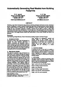
The example which I would like to present here is a simple trade model, “BakerWorld” [Boxed Economy Project, 2003]. The overview of the world is illustrated in Figure 14. There are two types of agents: Baker and Customer, where the baker bakes bread and sells them to the customer. In the following subsections, the diagrams in each phase are shown.
4 Boxed Economy Simulation Platform (BESP) is able to be downloaded freely from our web page (http://www.boxed-economy.org/). Or please contact us by E-mail to [email protected].
8
greeting
saying price
receiving order
demanding payment
Figure 15: Conceptual Model Class Diagram for BakerWorld
5.2
receiving money
Conceptual Modeling Phase
giving bread
In the conceptual modeling phase, we specify the characters in the target world and describe it in the conceptual-model class diagram (Figure 15). The baker is modeled as “BakerAgent”, and the customer is modeled as “CustomerAgent”. BakerAgent has “SalesBehavior”, and CustomerAgent has “ShoppingBehavior”. The relation between them is modeled as “FavoriteShopRelation”. Next step is to describing the activities of agents with activity analysis. The activities of BakerAgent are “greeting”, “saying price”, “receiving order”, “demanding payment”, “receiving money”, and “giving bread” (Figure 16). The activities of CustomerAgent are “saying hello”, “asking price”, “ordering”, “payment money”, and “receiving bread” (Figure 17). Third step is to describe the sequence of the communication among the agents (Figure 18). CustomerAgent sends the message “Hello!” to BakerAgent, then the BakerAgent replies the message “May I help you?”. After that, CustomerAgent asks “How much is it?”, and BakerAgent replies “100 yen”. CustomerAgent says “I want 3”, then BakerAgent calculates the sum and says “300 yen, please”. Finally, they exchange MoneyGoods and BreadGoods. The communication can be described in the communication-sequence diagram (Figure 18). The rest task is to define the goods and information. For Goods, there are BreadGoods and MoneyGoods (Figure 19). For Information,
Figure 16: Activity Diagram of BakerAgent for BakerWorld
saying hello
asking price
ordering
paying money
receiving bread
Figure 17: Activity Diagram of CustomerAgent for BakerWorld
9
Clock
CustomerAgent
BakerAgent
TimeEvent "Hello." "May I help you?"
"How much is it?" "100 yen."
Figure 19: Goods in the Conceptual Model Class Diagram for BakerWorld
"I want 3." Receiving Order "300 yen, please." Money Receiving Money Bread Receiving Bread
Figure 18: Communication-Sequence Diagram for BakerWorld there are PriceInformation and OrderInformation (Figure 20).
5.3
Figure 20: Information in the Conceptual Model Class Diagram for BakerWorld
Simulation Design Phase
In the simulation design phase, we modify the class diagram, which has been developed in the conceptual modeling phase. Then, we describe the statechart diagram of the agent’s behaviors. Figure 21 and 22 show the statechart diagram of ShoppingBehavior and SalesBehavior respectively. In addition, it is necessary to implements some action methods in Behavior classes. For example, the following source code is a method of ShoppingBehavior. protected void sayingHelloAction() { MessageInformation message = new MessageInformation("Hello!"); this.sendInformation(BakerWorldModel. RELATIONTYPE_FavoriteShopRelation, BoxTownModel.BEHAVIORTYPE_SalesBehavior, message); }
Figure 21: Statechart Diagram of ShoppingBehavior for BakerWorld
Next step is describing the initial settings of simulated world. The followings are the data for 10
Figure 23: BakerWorld on BESP social simulations. The tools are opened to public on http://www.boxed-economy.org/. Creating the foundation for the social simulations study is an oversized project for our members to complete. We would like to realize it by collaborating with many researchers in various fields. Please contact us, if you are interested in our challenge.
Figure 22: Statechart Diagram of SalesBehavior for BakerWorld initialization: • Agent – BakerAgent ∗ number = 1 ∗ Behavior = SalesBehavior
References
– CustomerAgent
[Boxed Economy Project, 2003] Boxed Economy Project. Designers Guide to Social Simulations. Fujita Institute of Future Management Research 2 edn. (2003). in Japanese.
∗ number = 1 ∗ Behavior = ShoppingBehavior • Relation
[Collier, 2003] N. Collier (2003). Repast: An extensible framework for agent simulation. The University of Chicago’s Social Science Research , http://repast.sourceforge.net/.
[Frankel, 2003] D. S. Frankel (2003). Model Driven Architecture: Applying MDA to Enterprise Computing (Wiley Publishing).
Verification Phase
[Iba and Takefuji, 2002] T. Iba and Y. Takefuji (2002). Boxed Economy Simulation Platform for Agent-Based Economic and Social Modeling in Computational Analysis of Social and Organizational Systems 2002.
Finally, we run the simulation in order to investigate whether the program works or not. There are two types of agents on the screen: BakerAgent and CustomerAgent (Figure 23). The BakerAgent sells BreadGoods to the CustomerAgent.
6
[Iba et al., 2002] T. Iba, Y. Chubachi, Y. Takabe, K. Kaiho, and Y. Takefuji (2002). Boxed Economy Foundation Model in The AAAI-02 Workshop on Multi-Agent Modeling and Simulation of Economic Systems pp. 78–83.
Conclusion
[Iba et al., 2002] T. Iba, Y. Takabe, Y. Chubachi, J. Tanaka, K. Kamihashi, R. Tsuya, S. Kitano, M. Hirokane, and Y. Matsuzawa (2002). Boxed
In this paper, we proposed the process and tools for Model Driven Development of agent-based 11
Economy Foundation Model: Toward Simulation Platform for Agent-Based Economic Simulations in Exploring New Frontiers on Artificial Intelligence pp. 227–236 (Springer-Verlag). [Iba et al., 2002] T. Iba, Y. Chubachi, Y. Matsuzawa, K. Asaka, and K. Kaiho (2002). Resolving the Existing Problems by Boxed Economy Simulation Platform in Agent-based Approaches in Economic and Social Complex Systems pp. 59–68 (IOS Press). [Kleppe et al., 2003] A. Kleppe, J. Warmer, and W. Bast (2003). MDA Explained: The Model Driven Architecture: Practice and Promise (Addison-Wesley). [Mellor and Balcer, 2002] S. J. Mellor and M. J. Balcer (2002). Executable UML: A Foundation for Model-Driven Architecture (Addison-Wesley). [Minar et al., 1996] N. Minar, R. Burkhart, C. Langton, and M. Askenazi. The swarm simulation system:a toolkit for building multiagent simulations. http://www.santafe. edu/ projects/ swarm/ overview/ overview.html (1996). [Parker, 2001] M. T. Parker (2001). What is ascape and why should you care? Journal of Artificial Societies and Social Simulation 4(1), http://www.soc.surrey.ac. uk/ JASSS/4/1/5.html. [Rumbaugh et al., 1999] J. Rumbaugh, I. Jacobson, and G. Booch (1999). The Unified Modeling Language Reference Manual (Addision Wesley Longman).