Feb 6, 2017 - Swarm robotics investigates how multiple robots, each with limited ability, ... machines are often adopted to design robot controllers in swarm.
From Formalised State Machines to Implementations of Robotic Controllers
arXiv:1702.01783v1 [cs.RO] 6 Feb 2017
Wei Li, Alvaro Miyazawa, Pedro Ribeiro, Ana Cavalcanti, Jim Woodcock and Jon Timmis
Abstract Controllers for autonomous robotic systems can be specified using state machines. However, these are typically developed in an ad hoc manner without formal semantics, which makes it difficult to analyse the controller. Simulations are often used during the development, but a rigorous connection between the designed controller and the implementation is often overlooked. This paper presents a statemachine based notation, RoboChart, together with a tool to automatically create code from the state machines, establishing a rigorous connection between specification and implementation. In RoboChart, a robot’s controller is specified either graphically or using a textual description language. The controller code for simulation is automatically generated through a direct mapping from the specification. We demonstrate our approach using two case studies (self-organized aggregation and swarm taxis) in swarm robotics. The simulations are presented using two different simulators showing the general applicability of our approach.
1 Introduction Safety is a major concern for autonomous robots, and the ability to provide evidence that a robotic system is safe can be demanding. Formal verification is the process of checking whether a design satisfies some requirements (properties) or that an implementation conforms to a design, and it has been used to verify a variety of robotic systems such as service robots [23] and swarming robots [20, 24]. Wei Li and Jon Timmis Department of Electronics, University of York, Heslington, York, YO10 5DD, UK. e-mail: {wei.li,jon.timmis}@york.ac.uk Alvaro Miyazawa, Pedro Ribeiro, Ana Cavalcanti, and Jim Woodcock Department of Computer Science, University of York, Heslington, York, YO10 5GH, UK. email: {alvaro.miyazawa,pedro.ribeiro,ana.cavalcanti,jim.woodcock}@ york.ac.uk
1
2
Authors Suppressed Due to Excessive Length
Swarm robotics investigates how multiple robots, each with limited ability, communicate, coordinate and self-organize to accomplish certain tasks. Swarm robotics has potential in a wide range of real-world applications such as search and rescue, object transportation and environmental monitoring [4]. While using a number of simple robots to collectively perform complex tasks is desirable, designing individual controllers to guarantee the emergence of certain swarm behaviour is challenging. If swarm robotic systems are to transfer from lab-based experiments to real applications, especially those that are safety-critical, the verification of the individual controllers as well as their resulting emergent swarm behaviours needs to be conducted in a rigorous way. Typically, the implementation of a robotic control system is conducted without establishing a strong connection between the controller code and the high-level design specifications. Here we explore the usage of a state-machine based notation, RoboChart [17], for designing robotic controllers. RoboChart has a formal semantics that allows for verification. In this paper, we extend RoboChart to support automatic code generation from the designed controllers to simulations. Finite state machines are often adopted to design robot controllers in swarm robotics [14, 10, 11, 2, 5]. A commonly used state-machine notation is that of UML [1]. RoboChart takes inspiration from UML, and provides facilities to model timed and probabilistic systems, composed of one or more controllers. Formal verification has been investigated in the design of controllers in swarm robotic systems [20, 24, 7, 12, 3]. In [24, 7], the authors used a temporal logic to formally specify and verify the emergent behaviour of a swarm robotic system performing aggregation. In [12], the authors used PRISM, a model checker for probabilistic automata, to formally verify the global behaviour of a foraging case scenario through exhausting all possible swarm behaviours. The analysis results were compared with those reported in [14], which used the test-driven simulation and showed a good correspondence. In these works, finite state-machine controllers were described using natural language, and there was no direct mapping from the high-level specification to low-level controller code. In [15], the authors applied supervisory control theory to control a swarm of robots. Their approach supported automatic code generation. The controllers were specified using standard finite state machines, without any of the extra facilities for architectural modelling available, for example, in UML. Various researchers have also explored the use of model-driven approaches to develop the high-level control of robots [21, 6, 22, 8]. The architecture analysis and design language (AADL) is a unifying component-based framework for modelling software systems with a particular focus on embedded real-time systems [8]. RoboChart could in principle be integrated into the controller component in AADL. In [22], a language was developed to program self-assembling robots. They proposed a role-based language that allowed the programmer to define the behavioural roles of each component independently from the concrete physical structure of the robots. However, in these works, the controllers of robots (e.g. state machine) were not formally specified, which makes it difficult to reason about robotic systems.
From Formalised State Machines to Implementations of Robotic Controllers
3
Graphical Tool
Textual Language code generation
simulators
physical robots
implementation
semantics generation
model checking
theorem proving
formal verification
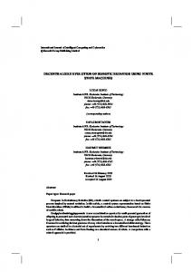
Fig. 1: The RoboChart framework for combining formalised state machines and implementation of robotic controllers.
The main contribution of this paper is to reduce the gap between high-level specification and implementation of robotic controllers. This paper is organized as follows. Section 2 briefly introduces RoboChart. This includes the elements of RoboChart and the approach to automatic code generation for simulation and deployment. Section 3 presents two case studies (self-organized aggregation [10] and swarm taxis [2]) in swarm robotics. The simulations using the automatically generated C++ code are presented. Section 4 concludes the paper and presents future work.
2 RoboChart Figure 1 shows the RoboChart framework to combine formalised state machines and automatic implementation of robotic controllers. Once the controller is developed, code is generated automatically to be used in different simulation platforms or physical robots. Formal semantics are also automatically generated for verification. Details of the formal semantics of RoboChart can be found in [17]. In the following section, we focus on the automatic code generation for simulation and deployment.
2.1 Elements of RoboChart Central to RoboChart is a state-machine notation. RoboChart machines include states and their entry, during and exit operations (actions), as well as transitions possibly triggered by events. The entry operation is executed when the robot enters a state, and followed by the execution of the during operation. When a transition is
4
Authors Suppressed Due to Excessive Length
triggered, the exit operation of the source state is executed. If an action is associated with the transition, it is also executed before the state machine enters the target state. Operations and events of a state machine are described in an interface. A state machine can requires an interface. An operation can either be described without implementation or implemented by the user in a state-machine style. An operation can include a precondition and a postcondition. Variables can be defined in a state machine, an interface or an operation. Different data types (primitive or composite) can be defined. When the behaviour is complex, multiple (potentially interacting) state machines can be used. In addition to state machines, RoboChart also includes elements to organize specifications such as modules and robotic platforms [17]. A module defines a system, including a robotic platform and associated controllers. Each controller can be specified by one or more state machines. RoboChart also includes time constraints. A clock can be defined inside a state machine to record the instant in time #T in which a transition is triggered. For example, the primitive since(T) yields the time elapsed since the most recent time instant #T. If since(T) is used as a condition (guard) on a transition with no events, then the transition will be taken immediately once the guard is true. Unless time is specified, we assume an operation takes no (or a significantly small) time. For full details of RoboChart, refer to [17].
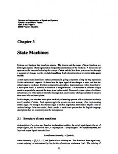
2.2 Simulation and deployment In RoboChart, the robot’s controller is specified either graphically or using a textual description language. The automatically generated controller code can be imported into a wide variety of simulation platforms. We adopt the model-view-controller (MVC) pattern in the design of simulations, where, the terms model and controller are used in a different way from that adopted in RoboChart. Figure 2 maps the RoboChart constructs to an MVC architecture. The model (M) component contains a simulation of the environment and of the RoboChart controller. We can generate a simulation of the RoboChart controller, potentially together with a simulation of the environment1 . The controller component (C) implements the robotic platform, which corresponds to a particular robot in a simulation. Finally, the view component (V) defines the visualisation of the simulation. We now describe how the controllers defined in RoboChart can be mapped into an executable language, specifically C++. Other object-oriented languages can be considered in a similar way, but are currently outside the scope of our work. The simulation of a controller is the simulation of its state machine(s). Each machine is implemented by a class. If the machine requires an interface, that interface is also implemented by a class, which is inherited by the state machine. 1
The specification of environment is still under development. Currently the environmental stimuli are manually defined in the simulation.
From Formalised State Machines to Implementations of Robotic Controllers Environment Controller M
Robotic Platform C
5
Interface V
Fig. 2: RoboChart simulations pattern
RoboChart states clocks interfaces
State machine class attribute of enumerated type attribute of timer class inherit interface class
RoboChart events variables operations
Interface class attribute of enumerated type attribute methods
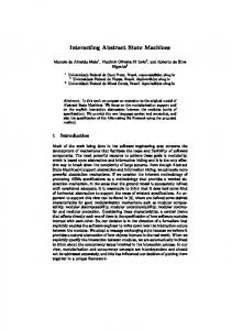
Fig. 3: RoboChart state machine and interface classes
Figure 3 defines how constructs of a state machine and interface are mapped to elements of a class. The variables and events defined in an interface are generated as attributes of the class. The operations (entry, during and exit) that the robot executes in a state give rise to methods. We note that, even if an operation is specified in a state-machine style, it is generated as a method. To update the state machine, some other methods such as MakeTransition are also generated. If a clock is defined in a state machine, a timer class is generated. It has a attribute counter, indicating the elapsed time, and methods such as StartTimer and ResetTimer. The state machine includes an object of the timer class as an attribute. The timer is used as a service of the state machine, which means the state machine can assess the counter. The state of the robot is updated in a cyclic manner, with the length of the cycle linked to the length of time required to capture events. The counter of the timer is updated in each control cycle. A primitive data type is directly mapped into one in C++. For example, the type real corresponds to double in the code. A composite type is generated as a predefined class. For example, vector2d corresponds to a 2D vector class. The data-type system in RoboChart as well as its mapping are still under development.
3 Modelling robotic controllers using RoboChart To demonstrate our approach, we investigate two case studies on canonical problems in swarm robotics: aggregation [10] and swarm taxis (flocking towards a beacon) [2]. In these case studies, the robots are homogeneous. The controller of each robot is defined by a single state machine, and it is executed in the e-puck [18], which is a differential wheeled robot. It has an inter-wheel distance of 5.1 cm. The maximum speed for the left and right wheels of the e-puck is 12.8 cm/s, forward or backward.
6
Authors Suppressed Due to Excessive Length
3.1 Case study one: aggregation 3.1.1 Aggregation behaviour In this behaviour, each robot is equipped with a line-of-sight sensor that detects the type of item in front of it. The range of this sensor is unlimited in simulation. It gives a reading of I = 1 if there is a robot in the line of sight, and I = 0 otherwise. The environment is free of obstacles. The objective for the robots is to aggregate into a single compact cluster as fast as possible. Each robot implements a reactive behaviour by mapping the sensor input (I) onto the outputs, that is, a pair of predefined speeds for the left and right wheels, (v`I , vrI ), v`I , vrI ∈ [−1, 1], where −1 and 1 correspond to the wheel rotating backwards and forwards respectively with maximum speed. The parameters of the aggregation controller were found by performing a grid search over the space of possible combinations [10]. The controller exhibiting the highest performance was: p = (v`0 , vr0 , v`1 , vr1 ) = (−0.7, −1.0, 1.0, −1.0) .
(1)
When I = 0, a robot moves backwards along a clockwise circular trajectory with a linear speed of −10.88 cm/s and an angular speed of −0.75 rad/s. When I = 1, a robot rotates clockwise on the spot with a linear speed of 0 and the maximum angular speed of −5.02 rad/s.
3.1.2 Modelling the aggregation controller in RoboChart Figure 4 shows the diagram of the aggregation controller modelled in RoboChart. An interface, AggregationIface, declares the variables, operations and events. The state machine (AggregationFSM) requires AggregationIface. The state machine has an initial node, i, pointing to the initial state. The aggregation controller includes two states (S1 and S2), two events (seeWall and seeRobot, which correspond to I = 0 and I = 1 respectively), and two operations (MoveClockwise and RotateClockwise). These operations are implemented in a state machine style with only an initial state S and final state F. Different from the AggregationFSM state machine, both operations have a final state. An operation can include precondition that must be satisfied by the caller to guarantee that the functionality of this operation is realised as specified. For example, in the MoveClockwise operation, the precondition requires that its first argument, an angular speed, is negative, and the second, the linear speed, is not zero. In the generated C++ code, this is realized using the assert function. A textual description of the AggregationFSM state machine and the MoveClockwise operation is shown in Figure 5. In the generated C++ code, two classes (AggregationIface and AggregationFSM) are generated. The class AggregationIface includes the attributes of two double variables (linearSpeed and angularSpeed), two methods (MoveClockwise
From Formalised State Machines to Implementations of Robotic Controllers AggregationIface
7
RotateClockwise(i: real): void
linearSpeed: real angularSpeed: real MoveClockwise(i: real, j: real): void RotateClockwise(i: real): void seeWall seeRobot
pre: i