From Functional Requirements through Test Evaluation Design to Automatic Test Data Patterns Retrieval – a Concept for Testing of Software Dedicated for Hybrid Embedded Systems Justyna Zander-Nowicka, Ina Schieferdecker MOTION, Fraunhofer FOKUS Kaiserin-Augusta-Allee 31 10589 Berlin, Germany {zander-nowicka, schieferdecker}@fokus.fraunhofer.de
Abstract - Functional testing of software dedicated for hybrid embedded systems should start at the early development phase and requires analysis of discrete and continuous signals, where timing constraints play a significant role. Test data generation is done manually nowadays, though it should be automated to the highest possible extent; system evaluation is mainly performed by application of reference signals, which however are not present during the design phase yet. Hereby, a concept for testing at the model level is introduced, due to which the transformation from requirements to test evaluation design occurs and finally semi-automatic derivation of test data is possible. There is no need for reference signals utilization, since characterization and extraction of particular signals’ features are provided for the comparison during the final test. Furthermore, patterns of feature generators are built and templates are proposed. Keywords: functional test, test generation, test evaluation, hybrid behavior
1
Testing of Software within Hybrid Embedded Control Systems
Embedded control systems are usually reactive with real-time dynamics, discrete events, and discrete mode changes. They use discrete signals for communication and coordination between system components and continuous signals for monitoring and controlling their environment via sensors and actuators [1]. Software in such systems is gradually becoming of even higher importance than hardware [2] due to the creation of new innovative functions based on software as well as the implementation of formerly mechanically or electronically integrated functions in embedded software.
Abel Marrero Pérez DaimlerChrysler Automotive IT Institute, Berlin University of Technology, Ernst-Reuter-Platz 7, 10587 Berlin, Germany
[email protected] To handle the software complexity of hybrid systems, model-based development is applied nowadays. It allows for models specification, code generation and for their first execution [3]. Such models and their requirements serve subsequently as a basis for testing, which is a central and significant task within software production. In this paper our goal is to support dynamic black-box software testing. Our technique handles discrete and continuous signals, and timing constraints between them. We assume that the requirements are available in forms of a textual specification and an executable model of the System Under Test (SUT). Moreover, we support testing on the Model in the Loop (MIL) Level [4], when neither code, nor hardware exists yet. This allows for resource and cost reduction during the entire software development process. Starting with the requirements and interfaces of the SUT model we build the test evaluation design applying already available templates and patterns. This is a novel approach as we model the test evaluation first – opposite to a common practice. We primarily evaluate the SUT based on the signals’ features, not on the reference signals; however we don’t exclude the latter method completely. Afterward, the test data patterns are retrieved from the test evaluation design automatically. They are refined by setting the appropriate parameters. Finally, the SUT model fed with the previously created test data is executed and the evaluation unit supplies verdicts on the fly. The message of this paper is that the test oracle specification is as much crucial as test data selection within testing process. Test evaluation has not been paid sufficient research attention in the past few years [5] as was paid to test data generation. The point is to achieve both so as to build the entire test case completely and obtain the test results automatically.
This paper is structured as follows: In Section 2 current work in relation to our solution is discussed. In Section 3 details of the proposed approach are discussed. In particular, signals’ features and their generators are characterized. Also templates for the technique application are provided. Section 4 presents the concepts based on an example. Conclusions finish the paper.
2
Related Work
In the following, available methodologies for testing the dynamic functional behavior of embedded systems are reviewed. The tool assessment is based on the test design availability, test data selection, test evaluation algorithms and their automation grade. An approach used mainly for checking temporal safety critical requirements is exposed in Safety Checker Blockset [6] and EmbeddedValidator [7]. It deals with a set of properties being the combination of model's variables that are connected to a proof operator (e.g. “NeverAfter”, “A_implies_B”). A test model typically expresses an unwanted situation (e.g. the cruise control should never be active while the driver is braking). The verification process assesses if this situation is reachable or not and on this base establishes the test outcome. The methodology represents model-checking approach, which we reuse for testing to some extent. The mentioned properties of the model contribute to the concept of signals’ features in our technique. Another approach described in [8] is based on examining the values of different signals flowing in the SUT. The common procedures are checking whether any of the elements of the signal at its input is nonzero or does not exceed specified limits during model execution. If it is the case, an assertion arises. This method covers relatively simple issues, without considering complex properties and dependencies between continuous signals. In the research presented in [9] watchdogs applicability is foreseen and exemplified. The watchdog is used for a single requirement and logs the violation of the respective model property in form of a Boolean output variable. Our evaluation mechanisms (i.e. validation functions) are similar to this approach, although we aim to structure and systematize our solution. Reactis Validator [10] provides a test framework to graphically express assertions that check a SUT for potential errors, and user-defined targets that monitor system behavior in order to detect the presence of certain desirable test cases. If a failure occurs, a test execution sequence is delivered and it leads to the place where it happens. However, no predefined patterns enabling a scalable and systematic test design are available. Our approach provides assertions enriched with preconditions
so as to enable activation of the assertion only when it is expected to be checked and by that to relate the evaluation with the test data. Patterns are also supported by our technique. The Time Partition Testing [11] supports the selection and documentation of test data on the semantic basis of socalled testlets and the syntactic techniques Direct Definition, Time Partitioning and Data Partitioning which are used to build testlets. Testlets facilitate an exact description of test data. Signal evaluation is performed mainly offline. The online evaluation means are limited and are used as watchdogs for extracting any necessary information for making test cases reactive [11]. The offline evaluation is based on the script language Python – with some syntactic extensions for typical test evaluation functions. A library containing complex evaluation functions is available [12]. TPT is platform-independent and can be used at several embedded software development stages, which we do not directly support with our solution. With the help of the next tool - Classification Tree Editor for Embedded Systems (CTE/ES) [3], [13], it is possible to set up value ranges for the individual ports and to combine these ranges in sequences. To represent test scenarios in an abstract way, they are decomposed into individual test steps [13]. Each test step defines the input situation at a certain time. A sequence of such test steps is called test sequence. The method combined with MTest tool [13] enables SUT output signals to be compared with previously obtained reference signals using a reprocessing component and the difference matrix method. We aim to avoid the need for creation and further utilization of reference signals. The verdict concept used for assessing the test outcomes occurs in such standards like UML 2.0 Testing Profile (U2TP) [14] or Testing and Test Control Notation – version 3 (TTCN-3) [15]. In TTCN-3 local verdicts contribute to a global verdict, which is calculated from the local ones based on the overwriting rules. Verdicts are assigned on the fly [15], [1]. Our solution corresponds to such verdict assessment and arbitration concepts. Our approach differs from those discussed before, since we start with the evaluation design instead of the test data selection. This is the condition for obtaining the test data patterns automatically. The test evaluation itself encounters a treatment of continuous and discrete signals on the fly. Since we assume that the reference signals are not available, we have to provide a method for evaluating the particular specific features of signals based on the requirements. Thus, we supply numerous signals’ features. We implement features extractors, comparators and features generators. Parts of this approach are presented in our previous work [16], [5].
Additionally, application of the same graphical modeling language for system and test design is aimed in our solution. This ensures the method to be relatively clear and it doesn’t imply to learn a completely new language. We provide a test framework, reusable test templates, generic validation functions designs and test data generators collected in a library. Our approach shows also some similarities to the previously mentioned methods. Some aspects of the evaluation of continuous signal’s features have been already described in [11] and [17]. Although we produce the test data patterns automatically, their concrete values must be completed. This could be supported by application of Classification Tree Method [3], as well as the management of data variants.
3
Proposed Test Approach
Table 1: Patterns for Extractors of Signal’s Features (excerpt)
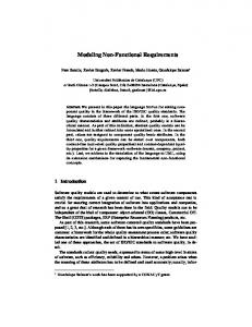
Basically, the support of functional, dynamic testing requires an analysis of the SUT specification, test data selection, an execution or simulation environment and test evaluation. Figure 1 presents a simplified view on the test architecture.
Figure 1: Common Test Harness
The SUT requirements specify its functionality and indicate the test objectives. Together with the interfaces of the SUT model they drive both – test data generation and test evaluation.
3.1
Validation Features
Functions
and
analyzed either using the predefined VFs or by creating new ones on the given templates. Our objective is to evaluate both discrete and continuous signals quality on-line, i.e. during a single model simulation. Similarly to [17] we aim to evaluate the SUT signals by their features. Under feature we understand an identifiable, descriptive property of a signal. We compare the features extracted from a signal with the expected values applying the VFs. We distinguish different feature types considering the feature availability on the one hand and the identification delay on the other hand [5]. However, their classification is out of the scope of this paper. Therefore, in the following we discuss only such features that are available for evaluation at every time step. Hence, the feature extraction computes its actual value at every time step. In Table 1 we present an excerpt from the list of the identified signals’ features due to the space limitation.
Signals’
We claim that at least a semi-automatic derivation of test evaluation design is possible. To achieve that, we propose an evaluation mechanism in the form of validation functions that are retrieved from the SUT requirements and SUT interfaces [16]. We define patterns of validation functions (VFs) that are able to continuously update the verdicts for a test case already during SUT execution. VFs are defined to be independent of the currently applied test data. They can set the verdict for all possible test data vectors and activate themselves (i.e. their assertions) only if the predefined conditions are fulfilled. The scalability of the test evaluation process is supported by a library/patterns extension mechanism. Systems may be
Signal evaluation – abstract view - Signal’s features time-independent 1. Signal value 2. Basic mathematical operations, e.g. zero detection 3. Detect increase 4. Detect decrease 5. Detect constant 6. Signal continuity 7. Derivative continuity 8. Linearity (with respect to the first value) 9. Functional relation y = f (x) (i.e. signal1 = f(signal2)) 10. Maximum to date 11. Minimum to date
3.2
From Requirements to Test Evaluation
Let us introduce the process of VFs creation. Having a single informal requirement, we organize a VF following a generic conditional rule:
IF
preconditions set
THEN assertions set
Preconditions set consists of a number of SUT signals’ feature extractors related to each other by temporal, logical or quantitative dependencies (e.g. FeatureA AND after(time1) FeatureB OR NOT(FeatureC)); a comparator for every single feature or dependency; and a unit for preconditions synchronization (PS). Assertions set looks similar, however includes a unit for preconditions and assertions synchronization (PAS), respectively. The details concerning synchronization problems are described in [5]. Hence, an abstract template for a validation function (shown in Figure 2) consists of a preconditions block which activates the assertions block, where the comparison of actual and expected signal values happens. The
activation and by that the actual evaluation proceeds only if the preconditions are fulfilled.
Figure 2: Structure of a VF – a Template1
The easiest assertions blocks checking time independent features are built following the schema shown in Figure 3.
Figure 3: Assertions Block – a Template1
They include a signal’s feature extraction part, a block comparing the actual values with the expected ones and PAS synchronizer. Optionally some signal deviations within a permitted tolerance range are allowed. We distinguish further schemas of preconditions and assertions blocks for triggered features discussed by [5] in details; however they are beyond the scope of this paper.
3.3
From Test Evaluation Design to Test Data Patterns – an Automatic Transformation
As we mentioned before the test data patterns can be retrieved from the test evaluation design automatically. During the test evaluation SUT input and output signals’ features are extracted. Hence, knowing the features appearing in the preconditions of a VF, we are able to reconstruct the test data from them. The preconditions typically depend on the SUT inputs; however they may be related to the SUT outputs at some points. Every time a feature extractor occurs for the assertion activation, a corresponding feature generator may be applied for the test data creation. In Table 2, test data generators for each feature appearing in Table 1 are presented.
duration time is default 6. Any continuous curve in the permitted range of values, where duration time is default 7. Any continuous curve in the permitted range of values, where duration time is default 8. Any linear function in the permitted range of values, e.g. described by the equation signal1=a*time+b, where duration time is default 9. Any function in the permitted range of values described by a concrete signal1 = f(signal2), where duration time is default 10. and 11. Any curve coming through a given max/min value in the permitted range of values, where duration time is default
Let us summarize the approach based on the simple, relatively abstract example in Figure 4. Assuming that a transformation from functional requirements into their conditional representation is already done, two VFs nested in the test evaluation unit are designed (see the right part of Figure 4). The preconditions encapsulate information about the test data demanded to activate the appropriate assertions. Applying the transformation according to the mapping rule that for each single precondition a corresponding signal generator is used, we obtain the test data patterns. The next step is to constrain the data with time. Either default or parameterized duration time of a single test case may be applied. We use a temporal constraint – after(time1) in the example below. Finally, further parameters (e.g. signal value, permitted value range) depending on the feature from which the corresponding signal is generated, are set. This is supported by the values contained in the precondition’s parameters. Hence, the test signals sequences are obtained. In Figure 4 the preconditions correspond to their test data. If the transformation is complete, the generated signals activate every single assertion one after another following the predefined time intervals.
Table 2: Patterns for Generators of Signal’s Features (excerpt) Test data patterns generation – abstract view - Signal’s features time-independent 1. Any curve coming through a given value within the permitted range of values, where duration time is default 2. Any curve described by a basic mathematical operation within the permitted range of values, where duration time is default, e.g. sinus crossing zero value within the permitted range of values, where duration time is default 3. and 4. Any increasing/decreasing function with a default/given slope and characteristics in the permitted range of values, where duration time is default 5. Any constant in the permitted range of values, where 1
The templates are designed in Matlab/Simulink/Stateflow [18]
Figure 4: Test Definition – Abstract View
In Figure 5 a similar situation as in Figure 4 is presented, but on the lower level of abstraction (i.e. using concrete signals). In VF1 all the values above the dotted line within the signal u1(t) activate the flag assertion. Thus, u1(t) is generated applying a corresponding pattern (first pattern from Table 1) and it is available within time ∈ (0, t1). Afterward, u1(t) remains unchanged and u2(t) increases within time ∈ (t1, t2) so as to enable the flag assertion in
VF2. In this example, no dependencies between features exist. Thus, the process of the test generation is completed.
Figure 5: Test Definition – Concrete View
Additional problems that may appear at the moment of data creation are caused by the dependencies (i.e. temporal, SUT inputs/outputs or another feature influences) between signals, which constrain the test data generators additionally. For some cases signal’s initialization and/or stabilization phase might be eligible so as not to let the previous test case influence the next one. Thus, in Figure 6 a template for test data generation is presented. For each data set determined by a single preconditions set, a block is provided, where features generation happens. Additionally, SUT output signals may be checked, if necessary. The features generation is activated by a Stateflow diagram sequencing the features in time according to the default temporal constraints (e.g. after(time1)). A switch is needed for each SUT input to handle the dependencies between generated signals. Initialization & Stabilization block enables to reset the obtained signal so that there are no influences of one test case on another.
Matlab/Simulink/Stateflow [18] environment to show the feasibility of our solution. It provides a simulation engine, which allows for the execution of tests, thus their dynamic analysis. It supports hybrid systems development and lets us use the same development language for both – system design and test design – so as to integrate testing and system modeling [16]. It also enables easier coverage of change requests throughout the development phases due to the advanced interface to the requirements. In this paper, a simplified component – Pedal Interpretation (Figure 7) of an Adaptive Cruise Controller developed by DaimlerChrysler AG is used for illustration purposes. This subsystem can be employed as pre-processing component for various vehicle control systems. The pedal interpretation interprets the current, normalized positions of acceleration and brake pedal (phi_Acc, phi_Brake) by using the actual vehicle speed (v_act) as desired torques for driving and brake (T_des_Drive, T_des_Brake) [3]. Furthermore, two flags (AccPedal, BrakePedal) are calculated, which indicate whether the pedals are pressed or not. Some excerpts of these functional requirements are given in Table 3. Table 3: Requirements for PedalInterpretation [3] (excerpt)
ID
Description
02
Interpretation of pedal positions Normalized pedal positions for the accelerator and brake pedal should be interpreted as desired torques. This should take both comfort and consumption aspects into account. 02.1 Interpretation of brake pedal position Normalized brake pedal position should be interpreted as desired brake torque T_des_Brake [Nm]. The desired brake torque is determined when actual pedal position is set to maximal brake torque T_max_Brake. 02.2 Interpretation of accelerator pedal position Normalized accelerator pedal position should be interpreted as desired driving torque T_des_Drive [Nm]. The desired driving torque is scaled in the non-negative range in such a way that the higher the velocity is given, the lower driving torque is obtained.* * A direct interpretation of pedal position as motor torque would cause the undesired jump of engine torque while changing the gear maintaining the same pedal position.
Figure 6: Test Data Generator – a Template
A similar approach applies for sequencing the test cases on the higher hierarchy level while dealing with a number of requirements. We call this process – test control and we consider it to be beyond the scope of this paper. A collection of VFs for different requirements and their corresponding test data generators nested in a well-defined architecture form a formal test specification for the SUT. Either without any further effort or with an additional refinement, the test specification can be utilized to evaluate the SUT behavior online during the test execution.
4
An Example Test Specification
This section demonstrates the use of the presented concepts for an example system. We selected the
Figure 7: PedalInterpretation Interfaces Table 4: SUT Inputs of PedalInterpretation Component VELOCITY PEDAL PEDAL (V) ACCELERATION BRAKE (PHI_ACC) (PHI_BRAKE)
m/s
%
%
NAME OF SUT INPUT Permitted values range Unit
Let us analyze requirement 02.2 for simplification. It is interpreted as such conditional rules: -
IF phi_Acc increases AND v is constant THEN T_des_Drive increases. IF phi_Acc decreases AND v is constant THEN T_des_Drive decreases. IF phi_Acc is constant AND v is constant THEN T_des_Drive is constant. IF phi_Acc is constant AND v increases AND T_des_Drive is non-negative THEN T_des_Drive does not increase.
The VFs for the formalized IF-THEN rules are designed as shown in Figure 8. Apart from the actual feature check, we deal here with preconditions that must be assured so as to activate the proper assertion. A similar cause-effect analysis resulting in scenario patterns is discussed in [19]. Note that only simplified excerpts of VF blocks are presented in the following. For further details please refer to [16].
Signal switches are used for connection of different features with each other according to their dependencies as well as for completing the rest of unconstrained SUT inputs with user-defined, deterministic data, when necessary. Considering the first VF and the first test data set from Figures 8 and 9 respectively, the following applies: If the velocity is constant and an increase in the acceleration pedal position is detected then the assertion is activated. As shown in Figure 10 – for the detection of a constant appearing in the preconditions, a constant signal is generated; its value is constrained only by the velocity limits , in this case it is set on 20 by a test engineer. For the increase detection, an increasing ramp limited in the range of the pedal position is utilized. Finally, userdefined data are assigned to the brake pedal position (e.g. peaks) since it was not constrained by the preconditions, what eventually enables to run this test.
Figure 10: Test Data for one selected Precondition Set Figure 8: Evaluation of Requirement 02.2
Let us focus on the test data patterns retrieval from the test evaluation design for this concrete example. Using the preconditions from Figure 8 and the template for test data generation from Figure 6, we obtain the design given in Figure 9 automatically. However, the retrieved test data patterns must be refined with the concrete values by a test engineer manually. It is possible due to the application of parameters available for every single test data pattern.
Figure 9: Derived Data Generators for Testing Requirement 02.2
The number of preconditions blocks in Figure 9 suits the number of VFs appearing in Figure 8. Sequencing of the features generation is performed in the Stateflow diagram.
If the desired torque increases as expected, pass verdict is delivered, otherwise fail appears. All the considered concepts of VFs and test data generators are provided in a Simulink library [18] that we created for testing purpose. Simulink libraries are collections of blocks that can be used in models. Blocks copied from a library remain linked to their originals such that changes in the originals automatically propagate to the copies in a model. Libraries ensure that the models automatically include the most recent versions of previously defined blocks and give fast access to the commonly used functions. The testing blockset contains VFs (i.e. feature extractors, comparators), data generators, templates and other elements needed to generate Simulink/Stateflow test models. Additionally, transformation functions are available. They are responsible for enriching the SUT with test evaluation templates, for detecting particular signal’s feature extractors in preconditions present in VFs and for retrieving the concrete test data based on this detection.
5
Summary
In this paper an approach to functional software testing on the model level is discussed. The innovation of this work results mainly from favoring the test evaluation design, which actually represents an abstract test specification. The preconditions within VFs are used for
the automatic generation of test data patterns. For these purposes, signals’ features are identified, patterns for test data generators and features extractors are provided, and templates for the entire test design are discussed. Transformations are supported so as to obtain a part of the test model automatically. The paper demonstrates the feasibility of the technique by providing an example. The presented VFs are created for component tests, however they may be re-used without any changes also for integration or system tests as similar issues must be evaluated on the higher integration levels.
[7] Bienmüller T., Brockmeyer U., Sandmann G.: Automatic Validation of Simulink/Stateflow Models, Formal Verification of Safety-Critical Requirements, Stuttgart, 2004
The next steps of our research relate to the variants management, optimization or grouping of the retrieved signals within the test data generation algorithm. We support only positive tests by now, thus the reciprocals of the generated data would be suitable candidates for further investigation.
[10] Cleaveland R., Hansel D., Sims S., Smolka S.: Reactis Validator, Embedded Software Design Automation, Reactive Systems, Inc., http://www.reactivesystems.com/tester.msp
The transformation of requirements into conditional rules may be complex for some cases. Thus, we will explore the specification driven tests and their relation to VFs modeling and test data generation. Additionally, we will investigate different types of signals’ features, their dependencies and influences in terms of test data retrieval. Finally, dependencies between test data and test cases (i.e. the influence of previous SUT state on the current test case execution, initialization and stabilization phases), the concept of online test reactiveness and test control will be subsequently within our research interest.
6
References
[1] Schieferdecker I., Bringmann E., Grossmann J.: Continuous TTCN-3: Testing of Embedded Control Systems, SEAS 2006, China, ISBN:1-59593-402-2 [2] Schäuffele J., Zurawka T.: Automotive Software Engineering, Vieweg, ISBN 3528110406, October 2006 [3] Conrad M.: Modell-basierter Test eingebetteter Software im Automobil: Auswahl und Beschreibung von Testszenarien. Dissertation, Deutscher Universitätsverlag, Wiesbaden (D), 2004 [4] Zander J., Dai Z. R., Schieferdecker I., Din G.: From U2TP Models to Executable Tests with TTCN-3 - An Approach to Model Driven Testing, TestCom 2005, Canada, ISBN: 3-540-26054-4
[8] Mathworks, Simulink Verification and Validation2, www.mathworks.com/products/simverification/ [9] Conrad M., Hötzer D.: Selective Integration of Formal Methods in the Development of Electronic Control Units, 144-Electronic Edition, ICFEM, 1998
[11] Lehmann E.: Time Partition Testing, Systematischer Test des kontinuierlichen Verhaltens von eingebetteten Systemen, Promotion, Technischen Universität Berlin, November 2003 [12] Lehmann E., Klaproth Ch., Krämer A., Ruhe J.: Time Partition Testing Manual, Version 0.9.9c, August 2004 [13] dSpace, MTest, www.dspace.de/ww/de/gmb/home/products/sw/expsoft/mt est.cfm [14] OMG: UML 2.0 Testing Profile. Version 1.0 formal/05-07-07. Object Management Group (OMG), 2005 [15] ETSI ES 201 873-1 V3.1.1: The Testing and Test Control Notation version 3; Part 1: TTCN-3 Core Language, 2005 [16] Zander-Nowicka J., Schieferdecker I., Marrero Pérez A.: Automotive Validation Functions for On-line Test Evaluation of Hybrid Real-time Systems, IEEE 41st Anniversary of the Systems Readiness Technology Conference (AutoTestCon 2006), IEEE Catalog Number: 06CH37750C, ISBN 1-4244-0052-X, ISSN 1088-7725 [17] Gips C., Wiesbrock H.-W.: Notation und Verfahren zur automatischen Überprüfung von temporalen Signalabhängigkeiten und -merkmalen für modellbasiert entwickelte Software, In: M. Conrad, H. Giese, B. Rumpe, B. Schätz (Eds.): MBEES - Model Based Engineering of Embedded Systems III, 2007, Dagstuhl-Workshop, TU Braunschweig Report TUBS-SSE 2007-01
[5] Marrero Pérez A.: Simulink Test Design for Hybrid Embedded Systems, Diploma Thesis, Technical University Berlin, 2007
[18] Mathworks, Matlab/Simulink/Stateflow, www.mathworks.com/products/matlab/
[6] Safety Checker Blockset, TNI-Software, www.tnisoftware.com/en/produits/safetycheckerblockset/index.php
[19] Tsai W.-T., Yu L., Zhu F., Paul R.: Rapid embedded system testing using verification patterns, In Software, IEEE Volume 22, Issue 4, July-Aug. 2005 Pages: 68–75