Semi-Automated Hw/Sw Co-design for Embedded Systems: from MARTE Models to SystemC Simulators Luis Gabriel Murillo, Marcello Mura and Mauro Prevostini ALaRI Institute, Faculty of Informatics University of Lugano Lugano, Switzerland Email:{murillol,muram}@alari.ch,
[email protected]
Abstract— Although MDE and Hw/Sw Co-design are widely used to address the design complexity problem, the lack of design procedures and methodologies joining both concepts restrains their usage as complementary techniques, thus preventing the implementation of faster and more robust design cycles. In this paper we present a practical semi-automated design flow where both methodologies are merged and exploited to enable a fast design process targeting highly complex Real-Time Embedded Systems, executing several tasks on SoC and MPSoC devices, while allowing the usage of Design Space Exploration, Schedulability Analysis and Estimation techniques.
I. I NTRODUCTION While fabrication technologies for integrated circuits evolve towards deep sub-micron levels, the semiconductor industry faces new design and development challenges mainly as a consequence of technology scaling and the increase in transistors number. This has a strong impact on system complexity that conflicts with the necessity for quick development of applications. Lately there has been a trend towards packaging more components in a single chip (i.e. SoC, NoC, and MPSoC devices) so to deal with power consumption and interconnect delay issues. The increased complexity impacts on design, development and management of new solutions, increasing both production costs and time to market. Therefore the creation and development of methodologies and techniques to support the design of complex systems and speed up related processes became a research field of main importance. Hardware-Software Codesing is a well-established methodology in the Embedded System community when dealing with complex systems. In particular it allows distributing activities of the system between Hardware Components (various information processing devices), and Software Components (code executed on those processing units). This methodology presents a step-based design flow for the design and refinement of complex systems. The starting point is the behavioral specification, then a sequence of different optimizations and refinements is performed in order to achieve the best possible final implementation. Evaluations are carried out using functions of merit based on design criteria (e.g. performance, power, area or combinations of them), on solutions still fulfilling the main functional and non functional requirements.
On the other hand, the Model Driven Engineering (MDE) methodology, in which an overall system specification guides the developers along the design process, was traditionally used by the software engineering community. Appropriate standardized design languages (e.g. UML [8] ), were used for this scope. MDE was recently extended also to the Embedded Systems field through appropriate UML profiles (as e.g. MARTE [5] or SysML [7]). Mechanisms are provided to describe structural, behavioral and non-functional specifications, in order to design a real-time embedded system from its model, supporting the entire development cycle. MDE and Hw-Sw Codesign offer different complementary characteristics that in theory could solve many of the problems related to the increasing systems complexity. Unfortunately this complementarity is not fully exploited: very few tools (e.g. [6]) have the capability of joining both domains, and automated or semi-automated design flows are lacking. This work addresses such lack studying a practical semi-automated design flow in which both methodologies are merged and exploited to enable a fast design process. We aim at helping in designing Complex Real-Time Embedded Systems, executing several concurrent and sequential tasks. Our methodology described in the next sections involves Allocation and Binding within Design Space Exploration, Schedulability Analysis, Hw/Sw Partitioning, and Estimation techniques. This paper is organized as follows, Section II presents the state of the art and some related works. A general overview on the theoretical foundations of this project is given in Section III. Section IV describes our proposal of a semi-automated design work-flow. Section V analyzes the code generation process and the transformations defined to obtain SystemC simulators from MARTE models. Results obtained when this approach was applied to design a wireless voice link are shown in Section VI. II. S TATE - OF - THE - ART AND RELATED WORKS In the last ten years some studies tried to use MDE for Embedded Systems design. Real time analysis using UML-
SPT profile1 [19] or other proprietary profiles, were carried out in [26], [25], [18], [15], and [27]. More recent works use MARTE profile for such scopes. In particular [11] introduces the Time Model subprofile of MARTE; [30] introduces concisely the Hardware Resource Model profile and then presents an appropriate methodology to apply it during the hardware design process; [13] highlights the expressiveness of MARTE notation for modeling regular distributions and clarifies its usage through examples and comparisons to other distribution notations such as in High Performance Fortran. Hw/Sw Co-design is a major focus in the literature and there were previous efforts to join such methodology with the techniques we use in this work. In particular in [17] and [9] UML-based hardware/software partitioning is explored, while in [20] the scheduling analysis view is shown as an extension of the design to improve real-time predictability. The most important contributions exposing complete design flows merging Hw/Sw Co-design and MDE can be found within the Gaspard2 toolchain in [14] and [28], where the authors present a chain generating a SystemC simulation tool targeting High Performance Embedded Systems (HPES) modelled using MARTE profile plus some extensions. Another interesting work bridging Co-design and MDE is the theoretical proposal of MoPCoM [3], in [21], where a design process leads to SystemC code generation from MARTE model specifications. Although Gaspard2 and MoPCoM address some codesign problems, such as code generation and synthesis, they don’t really provide support for the complete co-design cycle. In fact, those approaches leave outside essential concepts like Design Space Exploration, Allocation, Binding and Scheduling, that will be dealt with our approach. In this work we started from our previous approaches to join MDE and Hw/Sw Co-design, and along with the expansion to support further Co-design techniques of the mathematical structure describing Design Space Exploration in SysML, exposed in [16] and [22]; new SystemC code generation rules were created in addition to those shown in [23] aiming at mapping structural characteristics and other MARTE stereotypes. Finally our framework [24] was extended in order to allow better structural modelling and to add estimation techniques and scheduled execution to simulate real-time behavior. III. T HEORETICAL C ONTEXT Our previous works in Embedded Systems and SoC/MPSoC modeling, exposed in [22], were characterized by the usage of SysML as main design language, complemented with MARTE annotations for time and analysis modeling. This combination offers good flexibility when designing at high levels of abstraction (see e.g. [21]). In this work we chose to use only MARTE profile since it allows easier mapping for code generation, provides embedded systems specific model elements, and is fully supported by an open source tool, namely Papyrus for UML, which was used within this project. However, our semiautomated design flow can be used also with the SysML profile 1 The
previous standard UML profile (based on UML1.x) to model time.
as the transformations described in [23] can be adapted to those shown in section VI.
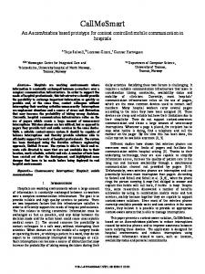
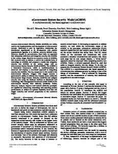
Fig. 1.
Hardware/Software Co-design Suggested Design Flow.
As mentioned before, the design process faces several challenges when dealing with modern hardware-software system. Application or target system complexity, and proliferation of numerous design objectives and constraints are the main issues that are traditionally dealt with Hw/Sw Co-design. A set of techniques are applied to a model in order to perform multiple optimizations and refinements, leading the system from an abstract stage to a physically implementable concept. Figure 1 represents the co-design flow and the components which are the basis of our MDE design process, as explained below: • Model: The system is represented by a model specifying both the Application and the Architecture. The applications is usually expressed in terms of Task Graphs (e.g. DFG, CFG), Process Networks (e.g. Kahn Process Networks, Synchronous Data Flow) or State Machines (e.g. StateCharts), depending on the models of computation. On the other hand the architecture specifies the processing units and the communication infrastructure of the system. • Mapping and Optimization: At system level, the mapping is composed of an Allocation (i.e. the selected processing units and communication resources), a Binding (i.e. assignment of tasks to selected components) and a Scheduling (i.e. execution order for the tasks). The allocation, binding and scheduling are produced on the basis of a multi-objective optimization criteria, examined through a Design Space Exploration (DSE). The process Mapping - Estimation - Optimization represents a recursive loop executed until the demanded cost-performance relation has been reached. • Estimation: After mapping, an estimation of the design properties of the next layers of abstraction should be made, so to anticipate the results due to design decisions at system-level. Accuracy of the estimation methods is a key point for a successful design. • Implementation: The output of the optimization process is composed of different design points, each one yielding cost-effective solutions (Pareto Points). The designer, based on the design objectives, should select one of these system configurations. The chosen system continues towards the development stage to be implemented.
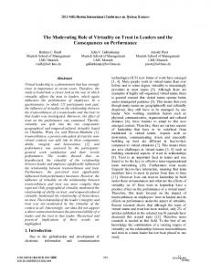
IV. C ODESIGN -D RIVEN M ODELING : I NTEGRATED D ESIGN F LOW This section presents our design methodology, merging a system engineering process with Hw/Sw Co-design capabilities, as part of a semi-automated procedure. The implemented workflow, described in Figure 2, features several model-tomodel transformations that allow to make design decisions and enable simulation of the system behavior. The CIM-PIMPSM cycle recommended by MDE is also followed through the entire process, making it possible to find a specific implementation starting from the system requirements. The flow starts with a preparation phase, which includes a requirements analysis, producing a set of functional and non functional specifications to be used in the model. If such information is not available it may be gathered through Rapid Prototyping, Simulation or Analysis of the System. In particular, the tasks Worst Case Execution Time (WCET) and/or Average Execution Time (AvgET) are mandatory for a proper design of a RTES targeting temporal correctness. Requirements and non functional specifications, as identified in the previous step, are used as input for the design phase. The design phase consists of the realization of structural and behavioral diagrams (corresponding to Co-design Application and Architecture models) that expose all the possible bindings, using the MARTE Allocation Modeling to allocate in temporal or spatial fashion. Timing information is captured by means of qualitative and quantitative annotations contained in the SAM (Schedulability Analysis Model) package. In the next section we will define the design rules in order to further explain how the MARTE packages, diagrams, and stereotypes are used inside our design cycle. The workflow continues in the co-design analysis phase with the generation of an XMI (XML Metadata Interchange) file from where data to perform a DSE on the allocation and binding options is gathered and provided to an Hw/Sw Codesign tool. All the possible bindings are first examined by a Schedulability Analysis tool in order to discard the combinations yielding time-incorrect (i.e. non respecting the realtime deadlines) solutions described within the requirements specifications. Then, among the remaining design points, after performing the multi-objective optimization through the DSE, the designer should select a Pareto-optimal point according to the desired cost criteria [12]. This design point, described by means of a UML/MARTE model is composed of an allocation, a binding and a scheduling. In the Simulation and Verification phase we generate the corresponding SystemC simulator necessary to check requirements, behavior and time correctness of the entire system. A. Design Rules Design rules are constraints yielding the selection of a suitable subset of MARTE to specify the system. The Embedded Systems domain is highly heterogeneous and it deals with several methods of computation, several application specific concepts and several architectural paradigms. The design rules,
Fig. 2.
Semi-automated Design Work-flow.
applied in the design phase of our workflow, are defined as follows: • The behavioral components are modeled using both Task Chains expressed by Activity Diagrams and StateCharts. Activities are used in a first stage to identify tasks that are allocated to architectural resources. StateCharts are used in a second stage to refine the description of such activities completely defining the behavior. • The structural components are defined with MARTE stereotyped classifiers and their communication is specified using ports and links, through a Composition Structure Diagram. The Architecture can be modeled at different levels of abstraction using the given MARTE subpackages, but the specific properties of highly detailed resources are not taken into account. • The communication resources are described as any other processing resource, and their behavior is described as part of the functional specification. • The architectural and behavioral components are stereotyped as recommended by the SAM package in order to enable the Schedulability Analysis of the system. The next subsection shows how the rules converted to MARTE stereotypes are mapped to a mathematical representation of the design phase. B. Mathematical Formalization and MARTE A new mathematical structure of the model is formulated based on the theory exposed in [22]. Each term in the equations is mapped to a MARTE model element and/or a UML diagram. The formalisms describes the model M as a four tuple structure, as follows: M = {A, F, B, T }
Notation
VA
EA F VF EF B
MARTE Stereotype and derived stereotypes N/A
UML Element
Classifier, Object
Port Activity Action ControlFlow, Transition Realization
TABLE I C ORRESPONDENCE BETWEEN THE MATHEMATICAL FORMALISM AND MARTE ELEMENTS
1) A = (VA , EA ) is the architectural specification graph, composed of available hardware resources VA and comwhere:munication links between them E ⊆(V ×V ). A A A 2) F = (VF , EF ) is the functional specification graph, composed of tasks (procedures) VF and edges EF ⊆(VF ×VF ) representing control flows. 3) B = { (vAi ,vF j ) ⊆ (VA ×VF ) | (vF j ,vF z ) ∈ EF ⇒ (vAi ,vAk ) ∈ EA ∀ (vAk ,vF z ) ∈ B } is a binding relation representing all the possible bindings and allocations respecting the constraints imposed by control flows and communication links. 4) T ⊆ (B × P) is the model elements characterization with non-functional properties (NFPs), where P = {p1 . . . pn } is a set containing NFPs as deadlines, execution times, priorities and scheduling methods. This formalization and all its terms are directly mappable to diagrams and MARTE stereotypes. The main specification graphs A and F are described by means of Composite Structure Diagrams and Activity/State Machine Diagrams respectively. The components of the P set are defined as properties from MARTE::NFP subprofile. The NFPs are given by stereotypes from the Design Model package and the GAM/SAM subprofiles (e.g. , , etc.). The rest of the structure is mapped to other UML components and MARTE stereotypes belonging to the Design Model, as shown in Table I. C. Co-design Analysis A Hw/Sw Co-design Analysis is performed to select an optimal implementation after the design phase has been completed. Although this work is not for studying in depth co-design algorithms, it is worth giving a subtle remark on how those algorithms are reached by our UML/MARTE Model. This phase consists of a set of Model-to-Model transformations, performed using XSLT rules, so to create new representations that expose time related information. Hw/Sw Co-design tools for performing Schedulability Analysis and Design Space Exploration (i.e. SymTA/S [6], MAST [2], Cheddar [1], Multicube Explorer [4]) are fed with the resulting
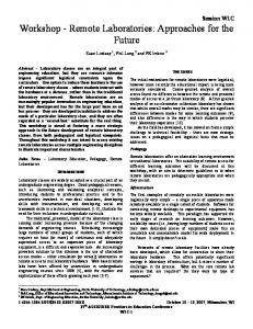
models in order to obtain those Pareto Points that yield timecorrect implementations. Following the design objectives an implementation candidate should be selected and simulated, to verify the behavior of the system. The automatic process generating the simulator is explained within the next section. V. C ODE G ENERATION : FROM MARTE M ODELS TO S YSTEM C The Automatic Code Generation process, explained in Figure 3, is central for the Simulation and Verification phase. For such scopes we extended the model-to-text transformation capabilities of our tool SC2 [24]. A structural-oriented adaptation of the framework based on the Architectural Specification Graph (A) was included, in order to generate code for the SystemC macro modules composing the simulator (i.e. Hardware Resources). A scheduler triggering behaviors allocated to architectural resources is also included as a module connected to all Hw resources. The code generation from behavioral components is performed following our original philosophy. Some changes were introduced in the SystemC mapping rules and the simulator structure so to improve the communication between modules making it more flexible. A. Architectural Extensions The SC2 project consists of an automatic generator of simulators which generates RTL SystemC code from StateCharts based models. The layout of the generated code is close to a synthesizable application, and this fact can be exploited when performing several refinements to the model. The framework is composed of a compiler-like system, with Front-end, Intermediate Representation (IR-XML) and Back-end. XSLT transformations are performed in order to map the XMI file created by the UML tool into a standardized XML format (front-end) and then from such format to the identified SystemC template (back-end). The produced simulators is made of modular SystemC code. The modules (i.e. SC MODULEs in the code) are bound to different State Machines Diagrams in the model. In case a State Machines Diagram contains more FSMs (parallel components or hierarchical separation), each FSM is mapped to a SC METHOD inside the same SC MODULE. Injection of user defined functions, a shell interface for simulation, and multiple instance creation from a single model are supported by the tool. While such framework provides a good solution for mapping behavioral MARTE models, it lacks mapping rules for architectural components and structures. The extensions we present in this work are mainly targeted to support mapping from MARTE architectural information to SystemC code. We also added the annotation of NFPs inside the code for evaluation phase. We modified the front-end so to allow recognition and parsing of MARTE stereotypes. This procedure involved also an improvement of the Intermediate Representation to incorporate such stereotypes (e.g. NFPs used inside the simulator) and collect when necessary the architectural information on the system. As we use Papyrus (because it
fully supports MARTE profile), our front-end takes as input XMI files generated by this tool. In the back-end more complex changes were needed to adapt the previous tool to our semi-automated flow. In particular modifications were necessary to redefine the structure of the generated simulator and support the inclusion of the hardware components as containers for behaviors (i.e. through stereotype). The SC MODULEs don’t correspond to State Machines Diagrams as in previous version, but to MARTE hardware resources. This change led to modify also the strategy used to communicate between State Machines. In the previous release it was not possible to customize inter-module communication. External modules were created corresponding to signals (declared in a class diagram); such modules were connected through ports to every module. In case of multiple instantiation the only possibility was to declare the variables as local or global. Local variables were connected to all the module of the particular instance, while global variables were connected to all the modules of all instances. In this work we enhanced such mechanism as we are able to represent the communication links between hardware resources. Thus the signals are connected to sc port< > and therefore communicated to the appropriate hardware block when the architectural diagram dictates so. Internal variables are mapped to sc signal< > and are only used inside the particular module. Behavioral information contained in a State Machine diagram, mapped to SC METHODs is used with the same transformation as in our previous tool. We added information coming from Activity Diagrams to control execution of the various tasks. A signal enables the scheduling of tasks. This signal is part of the sensitivity list of each SC METHODs and triggers its execution. When the task id identifier is received in the module (through a sc port< > connected to the scheduler) the corresponding task is first notified and then unblocked and executed. The scheduler in turn analyzes which tasks should start at a given time (for each module in the system), and then triggers the execution. Finally, once the task has been executed, each module sends a message to the scheduler to communicate its availability. If necessary task preemption can be implemented within this schema. Even though the SC METHODs can’t be stopped or restarted, our framework supports history. When a parent active state is created having all the state machines inside it and history enabled, the transition from this state to a suspend state emulates preemption. Using SC THREADs would simplify the matter but it has a cost on simulation speed and performance as explained in [24]. B. Translation Rules Mapping of MARTE stereotypes into SystemC code is essential to enable the translation process. The main rules are presented in Table II. Such rules refer to immediate mapping in which it is possible to directly transform a stereotype into a SystemC artifact. Similar rules have been previously presented
Fig. 3.
Automatic Code Generation Procedure.
for UML and SysML transformations into SystemC by several studies (e.g. [10], [29], [23]). SystemC
SC MODULE
sc port< > sc export< > SC METHOD sc signal< > sc clock
MARTE Stereotype and derived stereotypes ControlFlow, Transitions
TABLE II M APPING OF MARTE STEREOTYPES IN S YSTEM C CODE
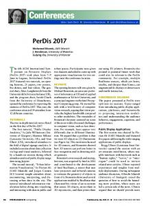
VI. C ASE S TUDY To show application of our complete methodology we take as a simple case study the design of a bidirectional wireless voice link with security provisions. We assume that we do not have the constraint that the two communicating nodes must be equal, therefore different bindings can be operated for them. The functionality of the system is as depicted in Figure 4: a data packet is prepared, security operations are performed and then the packet is sent through a wireless channel. This packet is received and appropriately decrypted/authenticated, then it is decoded. Our design space is described through the architectural graph drawn in Figure 4. We can decide whether include a coprocessor for security or not (both in transmission and in reception) and whether to develop and use a dedicated radio protocol (i.e. RadioB), with a much higher cost, or use the already existing IEEE 802.15.4 (i.e. RadioA). The architectural graph dictates some constraints caught by the Binding relation, as an example it is not possible to choose the couple Radio1A and Radio2B. The different choices have a different impact on the cost of the solutions as well as on the execution times. Data referring
and MDE. We show how it is possible to compress in a few diagrams complete information about the design space, feeding through convenient stereotypes a Hw/Sw Co-design tool to calculate Pareto Points. Moreover behavioral description through StateCharts is used to automatically generate simulators that are useful for evaluating systems performance. Using a convenient subset of MARTE UML profile we support the design flow from Design Space Exploration and Scheduling until automatic generation of SystemC Executable Models. Future work involves extension of the supported subset of MARTE profile and its mapping to more SystemC constructs as e.g. sc fifo< >. R EFERENCES [1] [2] [3] [4] [5] [6] [7] [8] [9] [10] [11] [12] [13] [14] [15] Fig. 4. Functional Specification Graph of our application and Architectural Graph Representation of our Design space
to WCETs are annotated in model through the stereotype and are shown in the picture as comments for clarity. Therefore such data can be sent to a scheduler. We deal with a simple case but our approach supports also more complex situation with actions that are concurrently executed. In our case we have a deadline of 40 ms for the entire activity that we expressed through the and this together with the architectural constraints led us to isolate valid bindings. The solution we took was to have 802.15.4 radios and security coprocessor mounted only in the first device. Having decided our solution the next step consists in refining the behavioral description completing the State Machine (StateCharts) diagram corresponding to the desired configuration. The framework provided us with a working simulator of our solution. We could use it to try with a characteristic data stream that the solution we chose respected the design constraints.
[16] [17] [18] [19] [20] [21] [22] [23] [24] [25] [26] [27]
VII. C ONCLUSIONS AND F UTURE W ORKS
[28]
In this paper we propose a framework that extends our previous works and brings them together in a wider research context in order to join the benefits of Hw/Sw Co-design
[29] [30]
http://beru.univ-brest.fr/ singhoff/cheddar. http://mast.unican.es. http://www.mopcom.fr. http://www.multicube.eu. http://www.omgmarte.org. http://www.symtavision.com. http://www.sysml.org. http://www.uml.org. W. Ahmed and D. Myers. Using UML 2.0 for the Creation of ConceptBased SoC Design. UML-SoC’07. P. Andersson and M. Hst. UML and SystemC - Comparison and Mapping Rules for Automatic Code Generation. on Selected papers from FDL’07, 2007. C. Andre, F. Mallet, and R. de Simone. Time modeling in MARTE. FDL’07. R. Bayton and R. Spence. Sensitivity and Optimization. Elsevier, 1980. P. Boulet, P. Marquet, E. Piel, and J. Taillard. Repetitive Allocation Modeling with MARTE. FDL’07. P. Marquet S. Meftali S. Niar A. Etien J. Dekeyser E. Piel, R. Attitalah and P. Boulet. Gaspard2: from MARTE to SystemC Simulation. proc. DATE 08. H. Espinoza, H. Dubois, S. Gerard, J. Medina, D.C. Petriu, and M. Woodside. Annotating UML Models with Non-Functional Properties for Quantitative Analysis. In Satellite Events at MoDELS 2005. S. Ganesan and M. Prevostini. Bridging the Gap between SysML and Design Space Exploration. FDL’06. P. Green and Y. Lu. Hardware/Software Partitioning of UML Models. UML-SoC’07. P.N. Green and M.D. Edwards. The modeling of Embedded Systems Using HASoC. In Proc. of DATE 02. Object Management Group. UML Profile for Schedulability, Performance, and Time. In OMG document n. ptc/02-03-02, 2002. M. Hagner and M. Huhn. Tool Support for a Scheduling Analysis View. UML Workshop at Date’08. A. Koudri, D. Aulagnier, D. Vojtisek, P. Soulard, C. Moy, J. Champeau, J. Vidal, and J.C. Le Lann. Using MARTE in a Co-Design Methodology. UML Workshop at Date’08. L.G. Murillo M. Mura and M. Prevostini. Model-based Design Space Exploration for RTES with SysML and MARTE. FDL’08. M. Prevostini M. Mura, A. Panda. Executable Models and Verification from MARTE and SysML: a comparative study of code generation capabilities. MARTE UML Workshop at DATE’08,. M. Mura and M. Paolieri. SC 2 StateCharts to SystemC: Automatic Executable Models Generation. FDL’07. M. Natale and M. Saksena. Schedulability analysis with UML. In UML for Real: Design of Embedded Real- Time Systems, Kluwer, 2003. D.C. Petriu and C.M. Woodside. Performance analysis with UML: layered queueing models from the performance profile. In UML for Real: Design of Embedded Real-Time Systems, Kluwer, 2003. T.H. Phan, S. Gerard, and D. Lugato. Scheduling Validation for UMLmodeled Real-Time Systems. ERCT 2003. J. Taillard S. Niar R. Atitallah, E. Piel and J. Dekeyser. From High Level MPSoC description to SystemC Code Generation. W. Raslan and A. Sameh. Mapping SysML to SystemC. FDL’07, 2007. S. Taha, A. Radermacher, S. Gerard, and J.L. Dekeyser. MARTE: UMLbased Hardware Design from Modeling to Simulation. FDL’07.