From Run-time Behavior to Usage Scenarios: An Interaction-Pattern Mining Approach Mohammad El-Ramly
Eleni Stroulia
Paul Sorenson
Department of Computing Science University of Alberta 221 Athabasca Hall, Edmonton, Alberta Canada T6G 2E8 1 780 492 2446
1 780 492 3520
1 780 492 1564
[email protected]
[email protected]
[email protected]
ABSTRACT A key challenge facing IT organizations today is their evolution towards adopting e-business practices that gives rise to the need for reengineering their underlying software systems. Any reengineering effort has to be aware of the functional requirements of the subject system, in order not to violate the integrity of its intended uses. However, as software systems get regularly maintained throughout their lifecycle, the documentation of their requirements often become obsolete or get lost. To address this problem of “software requirements loss”, we have developed an interaction-pattern mining method for the recovery of functional requirements as usage scenarios. Our method analyzes traces of the run-time system-user interaction to discover frequently recurring patterns; these patterns correspond to the functionality currently exercised by the system users, represented as usage scenarios. The discovered scenarios provide the basis for reengineering the software system into web-accessible components, each one supporting one of the discovered scenarios. In this paper, we describe IPM2, our interaction-pattern discovery algorithm, we illustrate it with a case study from a real application and we give an overview of the reengineering process in the context of which it is employed. Keywords Sequential pattern mining, software engineering, interaction reengineering, software requirements recovery, usage scenarios, run-time behavior analysis.
1. MOTIVATION AND BACKGROUND Any software application deployed and actively used within an organization requires to be continually evolved, through bug fixing, adaptations to its behavior and enhancements of Permission to make digital or hard copies of all or part of this work for personal or classroom use is granted without fee provided that copies are not made or distributed for profit or commercial advantage and that copies bear this notice and the full citation on the first page. To copy otherwise, or republish, to post on servers or to redistribute to lists, requires prior specific permission and/or a fee. SIGKDD ’02, July 23-26, 2002, Edmonton, Alberta, Canada. Copyright 2002 ACM 1-58113-567-X/02/0007…$5.00.
its functionality (Lehman’s Laws of Software Evolution [16]). In this process, the original functional requirements, even if they had once been properly documented, become blurred and outdated. This problem of “requirements loss” becomes especially critical when an existing software system needs to be reengineered in order to make its current functionality accessible through new platforms, e.g. the Web. Therefore, understanding the requirements of an existing software system is a key problem in softwareengineering research today. There has been a substantial body of research aiming at understanding and reverse engineering [6] software. To a great extent, this research has focused on analyzing the application code in order to extract a model of its static architecture in terms of high-level modules [12], [19]. But code is scarcely structured and often includes “dead” or obsolete fragments and “glue” code of incremental updates or “ignorant surgeries” [22] that violate the original software architecture. Even when the code is fairly well structured, the models produced by code analysis consist of modules that correspond closely to the syntactic constructs of the programming language in which the software was developed, and not to semantically coherent “packages of functionality”. Extracting and reusing such modules in the reengineered application may result in violations of the integrity of the underlying legacy information system. To obtain a richer understanding of software, planrecognition methods [23], [24] have been proposed. Given a representation of interesting software fragments, in terms of plans or clichés, the program-comprehension task becomes to recognize instances of these plans in the program. Since the representation language usually supports the functional specification of the plans and their instances, this approach can be quite effective in reverse engineering the functional requirements of programs, but is not scalable. In the context of more recent software-development methodologies, such as object-oriented for example, functional requirements are often specified in terms of usage scenarios. In fact, there has been some preliminary requirements-recovery research that, based on the analysis
of object-oriented code, produces specifications of use-case scenarios [8]. An alternative source of information regarding the usage scenarios of a program, applicable to all interactive applications and not only the object-oriented ones, is the run-time interaction between the program and the user. During this interaction, the program users follow these scenarios to accomplish their tasks. The CelLEST project [9], [10], [11], [15], [20], [21] adopts an interaction-based approach to reverse engineering; based on traces of the users’ interaction with a legacy application, it constructs a state-transition model of the legacy-interface behavior. In this context, the “software-requirements recovery” problem is formulated as a sequential-pattern mining problem. The underlying intuition is that traces of the run-time user interaction represent “walks” through the legacy interface model. Frequently occurring patterns in the traces can, then, be interpreted as purposeful “paths” executing the same type of task, and can thus be used as recaptured documentation of the functionality delivered by the legacy application. A similar rationale has motivated research on reverse engineering of work processes in collaborative virtual environments [4], where the environment data logs were mined to discover individual tasks, processes and sequences of tasks. The rest of the paper is organized as follows. Section 2 gives the context and the background of the “requirementsrecovery as interaction-pattern mining” problem. Section 3 presents the necessary terminology and formally defines the problem. Section 4 reviews the related pattern discovery literature. Section 5 presents IPM2, the algorithm we developed for interaction-pattern mining. Section 6 is a case study and evaluation of the algorithm. Finally, Section 7 summarizes our work to date, and concludes with the lessons we have learned and some pointers to future work.
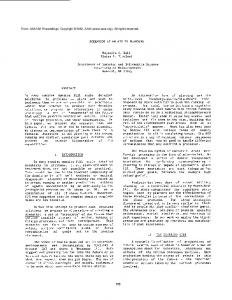
interface screens by a classifier induced after clustering the trace snapshots according to their visual similarity. Each transition in the model corresponds to a possible user action, that is, a sequence of cursor movements and keystrokes on a particular screen that causes the transition of the interface from the current screen to a new one. After an expert user has reviewed and validated the produced legacy-interface model, the next step is the discovery of frequently occurring interaction-patterns. The instances of a discovered interaction-pattern represent multiple executions of a single user task. Based on these examples, the user task can be modeled using a demonstrational-programming approach [7]. The resulting model, reviewed and elaborated by the user, specifies the information exchange between the user and the legacy application while performing the subject task. This model is, in effect, a scenario-like specification of some functionality of the legacy application. In the forward engineering phase of CelLEST, a declarative user interface specification for the modeled scenario is constructed by Mathaino [15], another prototype of the CelLEST environment. This specification is executable by a suite of special-purpose platform-specific components. Thus the new multi-platform user interface becomes a frontend for the original legacy user interface. It drives the underlying application by executing the instructions captured in the scenario model of the task, in the datatransfer protocol used by the original legacy system (See Figure 1). If we consider the new user interface as a taxi driver that saves an individual from walking (i.e. from using the legacy user interface), then the interface state-transition model is the road map. A task model is a path on the map, for going from an origin to a destination location using the map. The taxi is the API that traverses this path.
2. INTERFACE MIGRATION IN CelLEST The end-goal of the CelLEST project has been to develop an intelligent, lightweight, semi-automated method for legacy user interface reverse engineering and migration to the Web [9], [10], [11], [15], [20], [21]. Its fundamental methodological assumption is that the actual run-time behavior of the legacy application constitutes an operational specification of its desired functionality, i.e., the functionality actually exercised by its current users. Thus, the CelLEST process takes as input recorded traces of the system-user interaction on the proprietary legacy platform and produces as output a new, task-centered user interface (UI) accessible from a variety of Web platforms. The CelLEST method consists of two phases. In its reverse engineering phase, the Legacy Navigation Domain Identifier (LeNDI) prototype [9], [20], [21] produces a statetransition model of the legacy interface behavior. Each state of the model corresponds to a distinct screen in the legacy interface. Screen snapshots are classified into the distinct
Task Model State-transition Graph1
Task Centered GUI
State-transition Graph2
API to the Legacy Data Transfer Protocol
Text-based UI Legacy System 1
Text-based UI Legacy System 2
Figure 1: Legacy user interface migration: The CelLEST approach.
The cornerstone of the new front-end interface construction in CelLEST is the availability of examples of how the task scenario is currently accomplished with the legacy interface. These examples are mined as instances of frequently occurring patterns in the system-user traces, using IPM2, the CelLEST sequential-pattern mining algorithm.
2.1 An Example Case Study Let us now illustrate the CelLEST process with the case study that we will use later to evaluate IPM2. This case study was conducted with the Library Of Congress Information System (LOCIS)1. Four traces were recorded while a user retrieved detailed information about pieces of federal legislation through the LOCIS IBM 3270 public connection2. The user started by making the menu selections needed to open the relevant library catalog. Then he performed some information-retrieval tasks for several times. Figure 2.a shows 20 consecutive screen snapshots of one of the recorded traces with the keystrokes that occurred on each snapshot. The solid-line snapshots constitute an instance of the first user task. In this scenario, the user issued a browse (b) command with some keyword(s) to browse the relevant part of the library catalog file. Then he issued a retrieve (r) command to retrieve a subset of the catalog items. Then, he displayed brief information about the items in this set using display (d) command. Finally, he selected an item using the display item (d item) command to display its full or partial information, e.g. the full legislation, its abstract, its list of sponsors, its official title, etc. LeNDI built the corresponding state-transition model. Figure 2.b shows the part of this model that is relevant to the trace segment in Figure 2.a. The top left corner of every screen contains its ID, as given by LeNDI. The labels on the edges represent models for the user actions that enable the transition of the interface from a screen to another. The CelLEST interaction-pattern mining algorithm is used to discover the user tasks performed with LOCIS, in order to model and subsequently migrate them. Provided that a sufficient number of instances of each task appear in the recorded traces and that they meet some user-defined criterion for pattern interestingness, our method can discover that these instances represent a candidate interaction-pattern, even if some of the instances include some insertion errors. In this context, insertion errors are extra snapshots that may exist in the instances of a pattern, due to user mistakes or the existence of alternative paths for the same task. The pattern corresponding to the task instance of Figure 2.a is {4+,5,6+,7+,8+,9}, where + is one or more. In section 6, we discuss how this pattern was extracted. This pattern was subsequently augmented with the semantic 1
The IP address of LOCIS is 140.147.254.3 or locis.loc.gov The CelLEST project has focused mainly on legacy systems that use a block-mode data transfer protocol, such as IBM 3270. However, the underlying methods are more generally applicable. 2
information necessary for the forward reengineering phase of CelLEST. This includes specifying the information exchange between the user and the application on each screen, i.e. the user inputs to the system and the system outputs in return. Figure 3 shows the augmented interaction-pattern and a textual description of the corresponding scenario.
3. PROBLEM STATEMENT This section provides the terminology and formulation of the problem of discovering interaction-patterns in the recorded traces of interaction with a legacy user interface. 1. Let A be the alphabet of legacy screen IDs, i.e. the set of IDs given by LeNDI to the screens of the legacy system under analysis. 2. Let S = {s1,s2,….,sn} be a set of sequences. Each sequence si is an ordered set of screen IDs from A that represents a recorded trace of interaction between the user interface of the legacy system and one of its users, similar to the partial trace shown in Figure 1.a. 3. An episode e, is an ordered set of screen IDs occurring together in a given sequence. 4. A pattern p is an ordered set of screen IDs that exist in every episode e ∈ E, where E is a set of episodes of interest according to some user-defined criterion c. We say that e and E “support” p. We refer to the individual IDs in an episode e or a pattern p using square brackets, e.g. e[1] is the first ID of e. Also, |e| and |p| are the number of items in e and p respectively. 5. If a set of episodes E supports a pattern p, then the first and last IDs in p must be the first and last IDs of any episode e ∈ E, respectively, and all IDs in p should exist in the same order in e, but e may contain extra IDs, i.e. |p| ≤ |e| ∀ e ∈ E. Formally, • p[1] = e[1] ∀ e ∈ E, • p[|p|] = e[|e|] ∀ e ∈ E, and • ∀ pair of positive integers (i, j), where i ≤ |p|, j ≤ |p| and i< j, ∃ e[k] = p[i] and e[l] = p[j] such that k< l. The above predicate defines the class of patterns we are interested in, namely, patterns with at most a preset number of insertions. For example, the episodes {2,4,3,4}, {2,4,3,2,4} and {2,3,4} support the pattern {2,3,4} with at most 2 insertions. 6. The location list of a pattern p, written as loclist (p), is a list of triplets (seqnum, startLoc, endLoc), each is the location of an episode e ∈ E, where sseqnum is the sequence containing e. startLoc and endLoc are the locations of e[1] and e[|e|] in sseqnum, respectively. 7. The support of a pattern p, written as support (p), is the number of episodes in S that support p. Note that support (p) = loclist (p).length, the length of loclist (p).
8. The density of a pattern p supported by a set of episodes
E, written as density (p), is the ratio of |p| to the average episode length of episodes ∈ E: density (p) = |p| * support (p) ∑ |e| e∈E
9. A qualification criterion c, or simply criterion, is a user defined quadruplet (minLen, minSupp, maxError, minScore). Given a pattern p, the minimum length
minLen is a threshold for |p|. The minimum support minSupp is a threshold for support (p). The maximum error maxError is the maximum number of insertion errors allowed in any episode e ∈ E. This implies that |e| ≤ |p| + maxError ∀ e ∈ E. The minimum score minScore is a threshold for the scoring function used to rank the discovered patterns. This function is: score (p) = log2 |p| * log2 support(p) * density(p)
@E
133@E LOCIS Main Menu 3@E Federal Legislation Menu 11@E
Brief Display
Brief Display
d item 133@E
@E
Item Details First Page
Brief Display
b rep williams@E Catalog Browse Retrieve Results
Item Details First Page ottl@E
Item Details First Page @E
@E Item Details Last Page
@E
@E
@E Brief Display
Item Details First Page
Item Details Intrmd. Pg.
@E Brief Display
r b06@E
summ@E
all@E
@E Brief Display
Welcome
Item Details First Page
Item Details Intrmd. Pg.
Item Details Intrmd . Pg.
8
Item Details Intrmd. Pg.
1 LOCIS Main Menu 3@E
2 Federal Legislation Menu 11@E
@E
@E
First Page *@E
d item *@E
6
Brief Display
[*]@E
d *@E
4 Catalog
5 Retrieve
Browse
Results
@E
Item Details Last Page
@E
7 Item Details
3 Welcome b * [*]@E
9
r * [*]@E
@E
d 1@E
(a) A part of the LOCIS trace used in the example. @E means Enter key.
(b) The corresponding portion of the state-transition graph. * means a mandatory argument and [*] means an optional argument.
Figure 2: An example trace of user interaction with the Library of Congress Information System (LOCIS).
b * [*]@E
4 Catalog Catalog 44 Catalog Browse Browse Browse
r * [*]@E @ 23, 11
5 Retrieve Results d * @E @ 18, 8
ItemDetails Details 77 Item 7 Item Details First Page First Page First Page
d item *@E @ ?, 8
6 6
6
Brief Brief Brief Display Display Display
@E @ ?, 67 8 88 Item Details Item DetailsPg. Intrmd. Intrmd. Pg. Intrmd. Pg.
@E @ ?, ?
9 Item Details Last Page
(a) The interaction-pattern discovered for the information retrieval task of Figure 1.a, augmented with action locations. @ ?, 67 means that the user action occurs on the screen snapshot at an unspecified row and column 67.
____________________________________________________ Name: Retrieving Information on a Federal Legislation Participating actor: LOCIS User Entry condition: The user issues a browse command to LOCIS Flow of events: 1- Flip the catalog pages until the relevant page. 2- Issue a retrieve command to construct a results set for the chosen catalog entry. 3- Display the results set using display command and turn its pages until the required item is found. 4- Issue a display item command. 5- Specify a display option. 6- Display the item details. 7- Repeat steps 5 and 6 until retrieving the needed details Exit condition: The user retrieves the required information about the federal legislation of interest. ____________________________________________________
(b) A textual description of the corresponding usage scenario.
Figure 3: An interaction-pattern and the corresponding functionality described as a usage scenario.
Our experiments showed that this function is suitable and sufficient for our application as it considers and balances between the pattern length, its support and its density. The default values for minLen, minSupp, maxError and minScore are 2, 2, 0 and 0 respectively. 10. A maximal pattern is a pattern that is not a sub-pattern of any other pattern with the same support. 11. A qualified pattern is a pattern that meets the userdefined criterion, c. 12. A candidate pattern is a pattern under analysis that meets the minSupp and maxError conditions. Given the above definitions, the problem of interactionpattern discovery can be formulated as follows: Given (a) an alphabet A, (b) a set of sequences S, and (c) a user criterion c, Find all the qualified maximal patterns in S.
4. RELATED PATTERN MINING WORK Sequential-pattern mining is a generic problem with instances in a range of domains. It was first introduced in [1] under the name “mining sequential patterns”, inspired by applications in the retail industry, where given a set of customers and their sequences of transactions, the goal is to discover sequences of items (patterns) occurring in the transactions of the same customer. The interaction-pattern mining problem is different from the above, but similar to the problem of “discovery of frequent episodes in event sequences” [17]. In this problem, the discovered frequent episodes can have different types of ordering: full (serial episodes), none (parallel episodes) or partial and have to appear within a user-defined time window. The support of a pattern is measured as the percentage of windows containing it. Some Apriori-based algorithms were developed to tackle this problem, e.g. WINEPI and MINEPI [17] and Seq-Ready&Go [3]. The interaction-pattern mining problem is also similar to the problem of discovering patterns in genetic and protein sequences. There, the objective is to discover either probabilistic patterns or deterministic patterns with noise, e.g. flexible gaps, wild-cards (don’t care characters) and/or ambiguous characters (which can be replaced by any character of a subset of A) [5]. Because bio-sequential data is usually very large, an efficient search strategy is to discover short or less ambiguous patterns using exhaustive search, possibly with pruning. Then the patterns that have enough support are extended to form longer or more ambiguous patterns. This process continues until no more patterns can be discovered. Two elegant examples of this category are PRATT [14] and TEIRESIAS [13] algorithms. PRATT can discover patterns of the quite general PROSITE format [2], e.g. C-x(5)-G-x(2,4)-H-[BD], where B,C, D, G and H ∈ A, x(5) is a flexible gap of length 0 to 5, x(2,4) is a flexible gap of length 2 to 4, and [BD] is an ambiguous character that can be replaced by B or D. The
original TEIRESIAS algorithm discovers 〈L,W〉 patterns with wild-cards only, where L ≤ W. An 〈L,W〉 pattern has a constraint on its density, that is any of its sub-patterns containing exactly L non-wildcards items has length at most W. For example, CD..CH..E is a 〈3,5〉 pattern, where ‘.’ can be replaced by one ID ∈ A. None of these two algorithms handle patterns with insertion errors as in our problem. In the interaction-pattern discovery problem, the objective is to discover fully ordered patterns only, possibly with a number of insertion errors less than a predefined upper bound. It differs from the formulation of [17] in that it does not restrict the pattern length with a window length. In [10], we introduced a more restricted version of this problem, in which we discovered exact interaction-patterns with no insertion errors allowed, using an Apriori-based algorithm. But, since this severely limits the number and type of patterns retrieved, we needed to accommodate insertion errors. Since the problem formulations and the related algorithms mentioned above do not match our interactionpattern mining problem, we developed an algorithm, called IPM2 (Interaction-Pattern Miner 2), to solve it. IPM2 uses the strategy of developing longer candidate patterns from shorter ones. Like Web usage mining [18], IPM2 has three steps: preprocessing of input sequences, pattern discovery and pattern analysis. Unlike Apriori-based algorithms, IPM2 avoids multiple passes over the database by maintaining location lists of candidate patterns, which are used to generate the location lists of the longer composite patterns. IPM2 is an extension of our earlier algorithm, IPM [11]. IPM2 uses depth-first search instead of breadth-first search, used in IPM. This eliminates the need to store all the patterns of length l at the same time in a matrix |A| x |A| of patterns and their location lists, which can be memory exhaustive if the size of the alphabet A is big. So, IPM2 is more suitable for big systems with numerous screens. But this comes with the cost of generating more candidate patterns than IPM. IPM2 continually extends a candidate pattern by gluing patterns of length 2 to it, until it does not have enough support and then backtracks, and reports any maximal qualified pattern found.
5. INTERACTION-PATTERN MINING Let us now describe in detail IPM2, our algorithm for solving the problem of mining interaction patterns to recover the legacy system requirements as usage scenarios.
5.1 Preprocessing An interaction trace is initially represented as a sequence s of screen IDs, i.e. integers. We denote this representation as R0. R0 often contains repetitions, resulting from accessing many instances of the same screen consecutively, e.g. browsing many pages of a library catalog. Repetitions may result in missing some important patterns. For example the episode {4,5,6,6,6,6,6,6,7} in Figure 4 does not support the
pattern {4,5,6,7} if maxError < 5. To avoid this, we encode s using the run-length encoding algorithm that replaces immediate repetitions with a count followed by the repeated ID. Repetition counts are stored separate from the sequence. We call this representation R1. Figure 4 shows R0 and R1 representations of the trace segment of Figure 2.a. R0 : {1, 2, 3, 4, 5, 6, 6, 6, 6, 6, 6, 7, 7, 8, 8, 8, 9, 7, 7, 7} R1 : {1, 2, 3, 4, 5, (6)6, (2)7, (3)8, 9, (3)7}
Figure 4: Preprocessing interaction traces.
each of its consecutive IDs up to maxError +1. For example if sk = {1,3,2,3,4,3} and maxError = 2, the first ID will be tried with each of its next three resulting in the generation of these patterns {1,3}, {1,2} and {1,3}. Steps 6 and 7 add the new pattern in ptListVec, if it is not there. The location of the episode supporting the pattern is added to its location list in step 8. Steps 9 to 14 perform the same function as steps 2 to 8, but they handle the last maxError IDs of sk. Steps 15 to 18 remove any non-candidate pattern p, i.e. patterns with support (p) < minSupp.
5.2 Pattern Discovery with IPM2
Procedure 1
The input to IPM2 algorithm is a set of sequences S and a criterion c. IPM2 outputs all maximal qualified patterns in S. IPM2 consists of two distinct phases.
Input: An alphabet A, a criterion c and a set of sequences S. Output: All candidate patterns of length 2. Steps: 1. PatternList ptListVec [|A|]
First, it exhaustively searches the input sequences to find all the candidate patterns of length 2 that meet the “minimum support” and “maximum error” conditions (Procedure 1). For every such pattern, a location list is constructed. The patterns are stored in a vector of length |A| of pattern lists, ptListVec, whose cells are labeled after the IDs ∈ A. Each cell ptListVec[i] contains all patterns p, such that p[1]= i. For example, the pattern {1,3} is stored in ptLisVect[1].
2. For every trace sk ∈ S, 1 ≤ k ≤ |S| 3. For i = 1 to |sk| - maxError –1 4. For j = i +1 to i + maxError +1 5. Construct new pattern p = sk [i] + sk [j] 6. If p NOT in ptListVec [sk [i]] 7. then Add p to ptListVec [sk [i]] 8. Add (k,i,j) to loclist ( p)
In the second phase (Procedure 2), the algorithm recursively extends each candidate pattern in ptListVec using a depth-first approach. If an extension of a candidate pattern p1 using another pattern p2 produces a new candidate pattern p3 = p1+p2[2], then p3 is extended further. p1 can be extended only with patterns in ptListVec [p1[|p1|]], i.e. patterns of length 2 whose first ID is the same as the last ID of p1. The location lists of p1 and p2 are used to construct that of p3 (Procedure 3). The locations of the episodes that support p3, but have more insertion errors than maxError are excluded. If support (p3) ≥ minSupp then p3 is extended further using the patterns in ptListVec [p3[|p3|]], otherwise p3 is ignored and the algorithm records p1 if it is qualified and then backtracks. During backtracking and after reporting a pattern p1, the algorithm examines the parent pattern p0 of p1. Since p0 is a sub-pattern of p1, it is a candidate pattern also. If p0 is qualified and support (p0) > support (p1), i.e. it is not nonmaximal relative to p1, then it is recorded too. After trying to extend all patterns in ptListVec, non-maximal patterns are removed and only qualified maximal patterns are reported. 5.2.1 Procedure 1: Producing the Initial Candidate
Pattern Set The algorithm of Figure 4 describes the first procedure of IPM2 algorithm. Step 1 creates a vector ptListVec of pattern lists. PatternList is a hash-table-like data structure that can hold a list of hashed patterns. Steps 3 to 14 are repeated for every input sequence (trace) sk ∈ S. Step 3 iterates over the IDs of sk, from sk [1] to sk [|sk| - maxError 1]. In steps 4 and 5, each ID is used to build a pattern with
9. 10. 11. 12. 13. 14.
For i = |sk| - maxError to |sk| -1 For j = i +1 to |sk| Construct new pattern p = sk [i] + sk [j] If p NOT in ptListVec [sk [i]] then then Add p to ptListVec [sk [i]] Add (k,i,j) to loclist ( p)
15. For every id ∈ A 16. For every pattern p in ptListVec [id] 17. If loclist ( p).length < minSupp 18. then Remove p from ptListVec [id]
Figure 4: Procedure 1 pseudo-code.
5.2.2 Procedure 2: Generating Longer Candidate Patterns from Shorter Ones. The algorithm of Figure 5 describes the second procedure. Step 1 creates a pattern list, called resultsIPM2 to store the discovered patterns. Step 2 iterates over every cell id in ptListVec. Step 3 iterates over each pattern in ptListVec [id]. For every such pattern p, step 4 calls the “Extend (p1)” subprocedure, which returns all the qualified extension patterns of p that are maximal relative to each other, i.e. none of them is a sub-pattern of another one with the same support. Step 5 adds the discovered extensions of p to resultsIPM2. Step 6 removes any non-maximal pattern from the final results. Step 7 reports these results, i.e. resultsIPM2, back. The “Extend (p1)” sub-procedure works as follows. Step 1 creates a pattern list extensionResults to hold the patterns resulting from successful extensions of the parameter pattern p1. Step 2 iterates over every pattern p2 that can extend p1, i.e. every pattern whose first ID is the same as the last ID of p1. Steps 3 and 4 construct the extended pattern p3 and its location list. Step 5 tests if the support of
Procedure 2 Input: A vector of pattern lists initialized with all candidate patterns of length 2 and their location lists and a criterion c. Output: All the maximal patterns, qualified according to c. Steps: 1. PatternList resultsIPM2 2. For every id ∈ A 3. For every pattern p in ptListVec [id] 4. PatternList tempResults = Extend (p) 5. Merge tempResults with resultsIPM2 6. Remove non-maximal patterns from resultsIPM2 7. Report resultsIPM2 PatternList Extend (p1) 1. PatternList extensionResults 2. For every pattern p2 in ptListVec [p1[|p1|]] 3. Construct new pattern p3 = p1 + p2 [|p2|] 4. Construct the location list of p3 (Procedure 3) 5. If support (p3) ≥ minSupp Then 6. PatternList tempResults = Extend (p3) 7. Merge tempResults with extensionResults 8. If support (p1) > support (p3) 9. If |p1| ≥ minLen AND score (p1) ≥ minScore 10. If p1 is NOT in extensionResults 11. Add p1 to extensionResults 12. Else 13. If |p1| ≥ minLen AND score (p1) ≥ minScore 14. If p1 is NOT in extensionResults 15. Add p1 to extensionResults 16. Return extensionResults
Figure 5: Procedure 2 pseudo-code. p3 ≥ minSupp. Steps 6 to 11 are executed in case of True and steps 13 to 15 are executed in case of False. In case of a successful extension, step 6 extends the new candidate p3 more by calling Extend (p1) with p3 as a parameter. Step 7 adds the qualified patterns resulting from extending p3 to extensionResults. Steps 8 to 11 add p1 to extensionResults if it has more support than its successful extension p3, is qualified and is not already in extensionResults. In case of failing to extend p1 using p2, then the extension pattern p3 is ignored and steps 13 to 15 add p1 to the results list extensionResults if it is qualified and is not already in extensionResults. Step 16 reports back all qualified maximal (relative to one another) extension patterns of p1.
5.2.3 Procedure 3: Constructing the Location List of a Candidate Pattern. The algorithm of Figure 6 describes the procedure for creating the location list of a new candidate pattern. It combines the locations lists of two patterns p1 and p2, where |p2| = 2, to provide the location list of p3, where p3 = p1 + p2 [2]. Step 2 iterates over the locations of the episodes supporting p1. Steps 3 retrieves the location of such an episode e1. Step 4 retrieves the locations of the episodes that support p2 and satisfy some conditions. If we have such an episode e2, then:
Procedure 3 Input: The location lists of patterns p1 and p2 and maxError. The lists are sorted by seqnum and startLoc. Output: The location list of p3, where p3 = p1 + p2 [2]. Steps: 1. Create an empty location list listLoc3 2. For i = 1 to loclist (p1).length 3. loc1 = location i in loclist (p1) 4. Find a set Loc1 = (any loc2 ∈ loclist (p2)) such that loc2.seqnum = loc1.seqnum AND loc2.startLoc = loc1.endLoc AND loc2.endLoc ≤ loc1.startLoc + maxError + |p1| 5. For every loc1 ∈ Loc1 6. Add (loc2.seqnum, start, loc2.endLoc) to listLoc3 7. Remove any duplicates from listLoc3 8. Return listLoc3
Figure 6: Procedure 3 pseudo-code. • • • •
e1 and e2 should be in the same sequence e2 should not be a sub-episode of e2 and vise versa. e1 and e2 should overlap in exactly one location which is e1[|e1|]. The distance from startLoc of e1 to endLoc of e2, inclusive, should be no more than |p1| + 1 + maxError.
Steps 5 to 7 construct the location list of p3 and remove duplicates. Finally, step 8 reports the results back.
5.3 An Example Let us illustrate the operation of IPM2 algorithm with a simple example. Let A = {1,2,3,4}, S = {s1, s2}, where s1 = {1,3,2,3,4,3} and s2 = {2,3,2,4,1,3} and c = (minLen, minSupp, maxError, minScore) = (3,2,1,0). Discover all maximal qualified patterns in S according to c. Table 1 shows the result of applying procedure 1 of IPM2 to S. The second row corresponds to the cells of ptListVec. Patterns are enclosed between curved brackets, e.g. {1,2}, and their locations in the sequences are shown next to them between parentheses, e.g. (1,1,3). Candidate patterns are shown in bold. Patterns with insufficient support are shown in normal font. They are removed from ptListVec at the end of procedure 1, but are kept in Table 1 for clarification. Figure 7 shows the partial application of procedure 2 to extend 4 of the 8 candidate patterns in Table 1. The patterns in boxes are the ones being extended or resulting from extension. The patterns on the arcs are the ones used Table 1. ptListVec after procedure 1 for IPM2 application example. First ID ⇒
1
2
3
4
{1,2} (1,1,3) {2,1} (2,3,5) {3,2} (1,2,3)(2,2,3) {4,3}(1,5,6) {1,3} (1,1,2) {2,2} (2,1,3) (2,4,6) {3,3} (1,2,4)(1,4,6) (2,5,6) {2,3} (1,3,4)(2,1,2) {3,4} (1,4,5)(2,2,4) {4,1}(2,4,5) {2,4} (1,3,5)(2,3,4)
{1,3}
{2,3}
{2,4}
{3,2} {3,3} {3,4}
{3,2} {3,3} {3,4}
{4,3}
{1,3,2} {1,3,3} {1,3,4}
{2,3,2} {2,3,3} {2,3,4}
(1,1,3)
(1,1,4)
(2,1,3)
(1,3,6)
{2,4,3} (1,3,6) (2,3,6)
(1,3,5) (2,1,4)
{4,3}
{3,2} {3,3} {3,4}
{2,3,4,3}
{2,4,3,2} {2,4,3,3} {2,4,3,4}
(1,3,6)
{3,2} {2,3} {2,4} {3,2,3, 3} (1,2,4)
{3,2,4} (1,2,5)(2,2,4)
{4,3}
{3,2,4,3} (1,2,6)(2,2,6)
{3,2} {3,3} {3,4} {3,2,4,3,2} {3,2,4,3,3} {3,2,4,3,4}
Figure 7: The application of procedure 2 to 4 of the candidate patterns resulting from procedure 1 in the example. Table 2: All maximal qualified patterns discovered in IPM2 application example. Pattern p {2,3,4} {3,2,4,3}
|p| support (p) density(p) 3 2 0.86 4 2 0.80
score (p) 1.36 1.60
for extension. The location list of every generated pattern is shown under its box. Qualified patterns that are reported by the sub-procedure “Extend (p1)” are in bold font. Maximal qualified patterns, returned by IPM2, are in double-line boxes. Note that the pattern {3,2,4} is qualified but not reported by “Extend (p1)” because its extension {3,2,4,3} which has the same support, is reported first, while {2,4,3} is reported by “Extend (p1)” but is removed at the end of procedure 2 for being non-maximal. Table 2 shows the discovered maximal qualified patterns, their support, density and score.
5.4 Understanding the Extracted Patterns After reviewing the discovered patterns, the criterion c can be modified to narrow or widen the result set, if too few or too many patterns have been retrieved. Furthermore, a group of patterns, whose score and/or support are within specific range(s), can be selected and compacted by removing any pattern that is a sub-pattern of another pattern, even if it is maximal. This interactive step of scoping out and “cleaning” the extracted interaction patterns is crucial in identifying the usage scenarios corresponding to the functional requirements of the legacy application. Methodologically, the longer the recorded traces and the “stricter” the criterion c, the more likely it becomes to discover true usage scenarios, since all “noise patterns” should not gain enough support when evaluated in the context of long-term use. Ultimately, however, a user with knowledge of the application domain and the organization’s processes has to decide which of the discovered patterns correspond indeed to usage scenarios, corresponding to required functionality.
At that point, using the location list of each pattern, the pattern instances can be retrieved and analyzed in terms of the information exchange they support, in order to build task models for the forward engineering phase of CelLEST.
6. A CASE STUDY AND EVALUATION In this section, we present a demonstrative case study of recovering the usage scenarios of a legacy application from the run-time traces of the users’ interaction with it. We discuss the result of applying IPM2 to the case study we introduced in section 2.1. We recorded the traces of a LOCIS user, who was performing repeatedly various information retrieval tasks about federal legislation. The user conducted four sessions, using the IBM 3270 public connection of LOCIS. Each session was recorded as a data sequence. Thus, S ={s1,s2,s3,s4}, where |s1|, |s2|, |s3| and |s4| are 454, 185, 369 and 410 respectively. Part of s1 is shown in Figure 2.a. LeNDI, the reverse engineering tool of CelLEST, was used to build the state-transition model corresponding to S. Part of this model is shown in Figure 2.b. It has 26 nodes, each corresponds to a LOCIS system screen. Thus, A = {1,2,3,….,26}. The screen descriptions are shown in Table 3. The frequency (Fr.) of each screen is the number of times it was recorded in S. After preprocessing S, IPM2 was applied to S several times to discover the user’s interaction-patterns with LOCIS, and model them. Different parameters were tried for the criterion c to limit the size of the results set, so that it is easy to comprehend. Table 4 shows the 12 patterns discovered using the criterion c = (minLen, minSupp, maxError, minScore) = (6, 9, 1, 7), ordered by their score. The result set was further compacted by removing any pattern that is a subset of another pattern, leaving only the patterns with checkmarks in the last column. Where the last column has a number, this means that the corresponding pattern is a subset of the pattern with this serial number.
Table 3: LOCIS screen IDs, descriptions and frequency. ID 1 2 3 4 5 6 7 8
Screen Description Main LOCIS Menu Federal Leg. Menu Welcome Browse Result Retrieve Result Brief Display Display item 1/1 or 1st Display item (2/n or more/n) pg. 9 Display item (n/n) pg. 10 Help
Fr. 16 12 12 121 52 212 312 137
ID Screen Description 14 Select Result3 15 Combine Result4 16 Release Result5 17 Comments & Logoff 18 Goodbye 19 Ready for a Command 20 System Message 21 Livt Results (1/1) pg.6
Fr. 26 29 9 1 5 1 40 42
72 37
54 44
11 Error
84
12 Search History 13 Display List
57 5
22 Expand Results (1/n)7 23 Expand/Livt Results (n/n, i.e. last) page 24 Expand/Livt Results (2/n or more/n) pg. 25 Livt Results (1/n) pg. 26 Expand Results (1/1)
5 12 21
Next, we reviewed sample instances of each pattern, to see how well it corresponds to a real user task, i.e. to a usage scenario of the system. This inspection revealed that the four patterns in bold in Table 4 closely correspond to three repetitive user tasks, each has two alternative paths. The actual/complete interaction-patterns of these tasks are: 1. 4+-5-6+-7+-8+-9 or 4+-5-6+-7+-9 + + + + + 2. 4 -14-15 -6 -7 -8 -9 or 4+-14-15+-6+-7+-9 + + + + 3. 21 -22-23-22-6 -7 -8 -9 or 21+-22-23-22-6+-7+-9 Note that although S was in R1 format, by checking the instances of each pattern in the original sequences in R0 format, we knew which screens are consecutively repeated and added to them a + sign. The task corresponding to the first discovered interactionpattern was discussed earlier in subsection 2.1. In the second task, the user starts by browsing part of the currently open library catalog. Then he issues a select command to retrieve some records from the catalog. The select command constructs separate subsets of results for the specified search term, each for a different search field, e.g. one for the records that have the search term in the title, one for the records that have it in the abstract, etc. Then, the user issues a combine command to merge some of these subsets together into one set using some logical operators. Next, he displays brief information about the items in this set and selects some items to display their full or partial information.
3
Select command creates 1 or more record sets for a specified search term. Combine command creates a new set of records by logically combining previously created sets. 5 Release command releases search result sets not needed anymore. 6 Livt views Legislative Indexing Vocabulary Thesaurus online. 7 Expand command combines Livt and Select commands.
4
Table 4: The qualified maximal patterns discovered in LOCIS case study, using c = (6, 9, 1, 7). Pattern
1 2 3 4 5 6 7 8 9 10 11 12
21-22-23-22-6-7 22-23-22-6-7-8-9 23-22-6-7-8-9 22-23-22-6-7-9 21-22-23-22-6-7-9 4-5-6-7-9-7 6-7-8-9-7-4 7-4-14-15-6-7 22-23-6-7-8-9 22-22-6-7-8-9 22-23-22-6-8-9 22-23-22-7-8-9
Support Score Density
14 10 11 13 9 11 9 9 10 9 9 9
9.29 9.19 8.81 8.48 8.13 7.98 7.90 7.50 7.36 7.02 7.02 7.02
.94 .99 .99 .89 .91 .89 .96 .92 .86 .86 .86 .86
5 √ 2 5 √ √ √ √ √ √ √ √
In the third task, the user starts by issuing a livt command. This command takes as a parameter a term that is classified by LOCIS as a subject index term, and it displays all the related, broader and narrower terms available in the Legislative Indexing Vocabulary Thesaurus of LOCIS. For example, if the user likes to search for legislation related to drugs, but thinks it is a broad term, he can type livt drugs. The results screen will display terms like Anesthetics, Antibiotics, Antihistamines, Aspirin, Generic Drugs, Narcotics, etc. Next, the user can expand some of the displayed terms using expand command, creating a results set of catalog entries. Finally he displays the needed information as in the two other tasks. In all three scenarios the legacy system may follow one of two alternative paths to present the results to the user, depending on how many pages of details are retrieved for the legislation of interest.
7. CONCLUSIONS AND FUTURE WORK In this paper, we formulated the problem of recovering usage scenarios from the run-time behavior of an interactive application as an instance of the “sequential pattern mining” problem and we described the algorithm we have developed to address it. Usage scenarios are often used as specifications of an application’s functional requirements. Thus, extracting usage scenarios is tantamount to recovering the application’s functional requirements after their documentation has become obsolete. This is a crucial problem in the context of reengineering the application and migrating its functionality to new platforms, which is the end-goal of the CelLEST project. CelLEST postulates that user tasks can be found as patterns of frequently occurring similar episodes in the legacyinterface run-time behavior traces. These episodes may match only approximately. Users may face exceptional conditions while executing their tasks, and as a result the various instances of the same task execution may include spurious extra steps. The IPM2 algorithm was developed to
address exactly this requirement, i.e., to discover fully ordered sequential patterns with possible insertion errors. To date, we have evaluated this algorithm against a realistic case study with a real legacy application. We plan to evaluate it further with bigger artificial and real data sets (interaction traces), that cover a wide range of applications and interaction styles. Furthermore, we plan to compare its effectiveness and efficiency relative to other related algorithms, including our own earlier IPM algorithm. We believe that our interaction-pattern mining approach to legacy interface migration is an interesting variant of the sequential-pattern mining problem and a compelling application of this class of knowledge-discovery algorithms. As our initial results indicate, its deployment in the context of the CelLEST process can help provide a powerful, low-risk, lightweight solution to a challenging IT problem, namely the web-enabling of legacy applications.
ACKNOWLEDGEMENTS This work was supported by NSERC grant 215451-98 and Alberta Software Engineering Research Consortium (ASERC).
REFERENCES [1] Agrawal, R. and Srikant, R.. Mining Sequential Patterns. In Proc. of the 11th Int. Conf. on Data Engineering, 3-14, IEEE Comp. Soc. Press, 1995. [2] Bairoch, A. and Bucher, P. PROSITE: Recent Developments, Nucleic Acids Research, vol. 22, 35833589, 1994. [3] Baixeries, J., Casas, G. and Balcazar, J. L. Frequent Sets, Sequences, and Taxonomies: New, Efficient Algorithmic Proposals. Report Number: LSI-00-78-R, El departament de Llenguatges i Sistemes Informàtics, Universitat Politècnica de Catalunya, Spain, Dec. 2000. [4] Biuk-Aghai, R. and Simoff, S. Assisting the Design of Virtual Work Processes via On-line Reverse Engineering. In Proc. of 35th Hawaii Int. Conf. on System Sciences, IEEE Comp. Soc. Press, USA, 2002. [5] Brejova, B., DiMarco, C., Vinar, T., Hidalgo, S. R., Holguin, G. and Patten, C. Finding Patterns in Biological Sequences. Unpublished project report for CS798G, University of Waterloo, Fall 2000. [6] Chikofsky, E. and Cross, J.H.II. Reverse Engineering and Design Recovery: A Taxonomy. IEEE Software, vol. 7, no. 1, 13-17, Jan. 1990. [7] Cypher, A. (ed.). Watch What I Do: Programming by Demonstration, MIT Press, Cambridge, MA, 1993. [8] Di Lucca, G., Fasolino, A., and De Carlini, U. Recovering Use Case Models from Object-oriented Code: A Threadbased Approach. In Proc. of 7th Working Conf. on Reverse Eng. (WCRE 2000), 108-117, IEEE Comp. Soc. Press, 2000. [9] El-Ramly, M., Iglinski, P., Stroulia, E., Sorenson, P. and Matichuk, B. Modeling the System-User Dialog Using Interaction Traces. In Proc. 8th Working Conf. on Reverse Eng. (WCRE 2001), 208-217, IEEE Comp. Soc.
Press, Oct. 2001. [10] El-Ramly, M, Stroulia E., and Sorenson, P. Mining System-User Interaction Traces for Use Case Models. In Proc. of the 10th Int. Workshop on Program Comprehension (IWPC 2002), IEEE Comp. Soc. Press, France, Oct. 2002. [11] El-Ramly, M., Stroulia E. and Sorenson, P. Recovering Software Requirements from System-user Interaction Traces, In Proc. of 14th Int. Conf. on Software Eng. and Knowledge Eng. (SEKE’02), ACM Press, Italy, 2002. [12] Finnigan, P., Holt, R., Kalas, I., Kerr, S., Kontogiannis, K., Muller, H., Mylopoulos, J., Perelgut, S., Stanley, M. and Wong, K. The Software Bookshelf. IBM Systems Journal, vol. 36, no.4, 564-594, 1997. [13] Floratos, A. Pattern Discovery in Biology: Theory and Applications. Ph.D. Thesis, Department of Computer Science, New York University, Jan. 1999. [14] Jonassen, I. Methods for Finding Motifs in Sets of Related Biosequences. Dr. Scient Thesis, Dept. of Informatics, Univ. of Bergen, 1996, [15] Kapoor, R. and Stroulia, E. Simultaneous Legacy Interface Migration to Multiple Platforms. In Proc. 9th Int. Conf. on Human-Computer Interaction, vol. 1, 51-55, Lawrence Erlbaum Associates, Aug. 2001. [16] Lehman, M., Ramil, J., Wernick, P. and Perry, D. Metrics and Laws of Software Evolution – The Nineties View. In Proc. of the 4th Int. Software Metrics Symposium (METRICS '97), 20-32, 1997. [17] Mannila, H., Toivonen, H. and Verkamo, A. I. Discovery of Frequent Episodes in Event Sequences. Data Mining and Knowledge Discovery, vol.1, no. 3, 259-289, Nov. 1997. [18] Mortazavi-Asl, B. Discovering and Mining User Webpage Traversal Patterns. M.Sc. Thesis, The School of Computing Science, Simon Fraser Univ. Canada, 2001. [19] Müller, H., Orgun, M., Tilley, S. and Uhl, J. A reverse engineering approach to subsystem structure identification. J. of Software Maintenance: Research and Practice, vol. 5, no. 4, 181-204, Dec. 1993. [20] Stroulia, E., El-Ramly, M., Kong, L., Sorenson, P. and Matichuk, B. Reverse Engineering Legacy Interfaces: An Interaction-Driven Approach. In Proc. 8th Working Conf. on Reverse Eng. (WCRE 1999), 292-302, IEEE Comp. Soc. Press, 1999. [21] Stroulia, E., El-Ramly, M., Sorenson, P., and Penner, R. Legacy Systems Migration in CelLEST. Short Research Demonstration. In Proc. of the 22nd Int. Conf. on Software Engineering (ICSE 2000), pp. 790, Ireland, 2000. [22] Parnas, D. Software Aging. in Proc. 16th Int. Conf. on Software Engineering (ICSE'94), 279-287, 1994. [23] Quilici, A., Woods S. and Zhang, Y. Program Plan Matching: Experiments with a Constraint-Based Approach. Science Of Computer Programming, vol. 36, no. 2-3, 285-302, 2000. [24] Wills, L. Automated Program Recognition: A Feasibility Demonstration. Artificial Intelligence, vol. 45, no. 1-2, 113-168, Sept. 1990.