vehicle for modeling agent rationality, explicitly representing the agent's knowl- ... design stage consists in determining the roles (seller, buyer, broker, auction.
From UML Diagrams to Jess Rules: Integrating OO and Rule-Based Languages to Specify, Implement and Execute Agents M. Martelli and V. Mascardi DISI – Via Dodecaneso 35, 16146, Genova, Italy martelli,mascardi @disi.unige.it
�
Abstract. The paper discusses the D-CaseLP multi-agent system (MAS) prototyping environment and the software engineering aspects that it helps to face. The target implementation language of agents developed using D-CaseLP is Jess, a language inspired by the CLIPS expert system shell allowing to supply knowledge in the form of declarative rules. The choice of a declarative implementation language is motivated by the recently growing interest in this technology as a vehicle for modeling agent rationality, explicitly representing the agent’s knowledge, verifying system properties, enhancing knowledge sharing and communication. The MAS developer can directly implement agents using Jess, or she/he can take advantage of the D-CaseLP automatic translation process from UML into Jess. The last choice allows to exploit well established use-case driven and object-oriented methods for capturing the MAS requirements and specify some MAS issues (interaction protocols followed by agents, MAS architecture, agent types and instances) in a graphical way. Jess agents, being defined by hand or obtained as the output of the automatic translation process, are finally integrated into the JADE platform and executed.
1 Introduction Declarative specification and implementation languages, such as functional, logic and rule-based ones, are mainly used in the academic world. The specification of industrial software is usually carried out adopting object-oriented analysis and design approaches, while its implementation is mainly realized using imperative or object-oriented languages. One of the reasons of this approach is that concepts, notations and methods associated with object-oriented analysis and design techniques (and UML in particular) are increasingly familiar to a mass audience of software engineers. Also, object-oriented and imperative languages such as Java, C++ and C are definitely more widespread in industrial companies than Prolog, ML, or rule-based languages a` la CLIPS. This is usually motivated by reasons of efficiency. Nevertheless, there are many industrial application fields where a declarative approach to both specification and implementation should be preferable to a traditional OO or imperative one. Besides being reusable, declarative knowledge is more modular and flexible than imperative knowledge. It has better semantics, makes detecting and correcting contradictory knowledge easier, and provides abstraction of the (real) world
in a natural way. The use of meta-programming techniques in a declarative setting provides a support for the integration of different kinds of knowledge. It is our opinion that these features make the declarative paradigm a suitable solution for developing and verifying prototypes of complex applications, where a set of autonomous, intelligent and distributed agents cooperate and coordinate the exchange and integration of knowledge within a Multi-Agent System (MAS). In this paper we propose an integration of OO and declarative approaches that exploits both the benefits of the declarative approach to the development of MAS and the diffusion of the UML graphical language to specify different aspects of complex systems. We discuss the D-CaseLP prototyping environment which allows us to describe the interaction protocols followed by agents, the MAS architecture and the agent types and instances using UML, and to automatically create the rule-based code for the agents in the MAS in such a way that the UML specification is satisfied. The obtained code must be manually completed by the developer with the behavioral knowledge which was not explicitly provided at the specification level. This completion step does not require a deep insight in rule-based languages and is guided by comments included in the automatically generated code. In this way, a developer who is not confident with rule-based languages can concentrate on the UML specification and make a little effort to complete the rule-based code in order to make it executable. On the other hand, the developer who prefers to define agents in a declarative language, can skip the UML specification stage and directly write the Jess code. A software engineering methodology supports the engineer and developer from the requirement capture stage to the prototype execution stage. As far as requirement analysis is concerned, we adopt an existing multiview, use-case driven and UML-based method [3,4]. As a by product of our approach, we are able to check the coherence of the UML artifacts produced as an output of the requirement analysis stage thanks to the execution of the working prototype. Checking the coherence of UML diagrams is a well known and still open problem that we succeed to face almost for free. The structure of the paper is the following: Section 2 introduces the D-CaseLP prototyping environment and how it helps to face the modeling, implementation and execution stages. Section 3 sketches the requirement analysis stage. Section 4 clarifies the resulting integrated method and shows a simple example involving all the engineering stages, from requirement analysis to execution. Section 5 concludes.
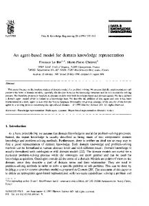
2 The D-CaseLP AOSE tool D-CaseLP (Distributed CaseLP, [1]) is a MAS rapid prototyping environment designed and developed by the Logic Programming Group of the Genova University Computer Science Department. It is based on CaseLP [10] from which it inherits the agent and MAS model. D-CaseLP provides languages and tools for facing the engineering of a MAS from the architectural design stage to the implementation of a working prototype. The architectural design stage consists in determining the roles (seller, buyer, broker, auction manager, etc) necessary for the application, establishing the complete role model (i.e.
the interaction protocols which may take place among roles), grouping the roles in agent classes, assigning the most suitable architecture (rule-based, BDI, etc 1 ) to each class and finally determining the needed agent instances. The languages provided for facing this stage include an extension of UML and its XML-based textual counterpart, D-CaseLP-XML. Diagrams which only include standard UML constructs can be graphically modeled with existing UML-based modeling tools. The implementation of the working prototype is the most original contribution of D-CaseLP: it exploits the XSLT technology (http://www.w3.org/TR/xslt) and the ability to export UML diagrams into the XML Metadata Interchange Format XMI to automatically generate rules which respect the given UML diagrams. The rule-based language we choose for the implementation of D-CaseLP agents is Jess (http://herzberg.ca.sandia.gov/jess/). The core Jess language is compatible with CLIPS (http://www.ghg.net/clips/CLIPS.html), the C Language Integrated Production System developed in 1985 at the NASA’s Johnson Space Center to satisfy NASA’s need of a reliable, efficient and low cost expert system. Jess uses the Rete algorithm [8] to process rules and extends CLIPS with some features including backwards chaining, working memory queries, and the ability to manipulate and directly reason about Java objects. Some portions of the Jess code generated starting from the UML diagrams must be completed by the developer in order to make it executable. Once completed, the Jess code can be integrated into the FIPA-compliant JADE platform [5], and the resulting JADE prototype can be executed. JADE offers already implemented tools to monitor and debug the prototype.
1) choose tool 2) define models Spec. in Ration. Rose
Spec. in
Spec. in
Together
ArgoUML
3) export
Spec. in XMI
4b) translate
4a) specify Specification in D−CaseLP−XML
5) translate
6) complete JESS rules
Java classes to interface JESS with JADE 7) execute JADE+JESS
Fig. 1. MAS modeling, implementation and execution in D-CaseLP.
1
At the time of writing only the rule-based architecture is available for implementing agents.
The concatenation of modeling, implementation and execution stages is graphically depicted in fig. 1 where activities on the left are manually carried out by the developer and activities on the right are completely automatic (note that activity 4a represents an alternative to the sequence of activities 1; 2; 3; 4b). The following sections discuss them in detail. 2.1 Modeling stage: D-CaseLP protocol, agent and architecture diagrams The MAS static architecture is defined by three diagrams: protocol, agent and architecture. When choosing an UML-based tool for their modeling2, the developer should verify that it allows to export UML diagrams into the XMI. D-CaseLP protocol diagrams are mainly based on AUML protocol diagrams [11,12]. With respect to AUML there are some restrictions to avoid ambiguities and to allow a complete automation of their translation into Jess: 1. in each protocol there is only one initiator role; 2. if more than two roles are involved in a protocol, the protocol must be split into sub-protocols, each one involving only two roles; 3. boolean connectors for concurrent delivery of messages are represented in an explicit way: the thread where the boolean connector appears is divided into as many threads as the messages to deliver, connected by the boolean connector. From each thread a message is sent. To make an example, fig. 2 represents a correctly modeled D-CaseLP protocol diagram corresponding to the FIPA Request Interaction Protocol [9] where an explicit notification of acceptance (the AGREE message) is needed.
Initiator_Role
Participant_Role REQUEST
REFUSE AGREE
FAILURE INFORM−DONE INFORM−RESULT
Fig. 2. Request Interaction Protocol.
In D-CaseLP the entities participating to a protocol are roles, and not agent instances, from the specification phase to the prototype implementation. The association 2
Protocol diagrams may include extensions to the standard UML definition: it is not always possible to graphically specify them using existing tools. In this case, the developer should specify the diagrams directly into D-CaseLP-XML.
between a role and the agent classes playing that role, between an agent class and its architecture, and between an agent instance and an agent class are defined in separate architecture and agent diagrams. D-CaseLP architecture diagram models the associations between an agent class, its architecture (relation has architecture) and one ore more roles it may play (relation plays role), while the agent diagram is used to associate each agent instance to its agent class and to its initial state. Architecture and agent diagrams are similar to the ones proposed in [6]. 2.2 Implementation stage: from UML to Jess To obtain a working prototype where agents respect the modeled UML diagrams the following steps must be faced: 1. XMI file generation: the diagrams are exported into XMI. 2. Translation from XMI to D-CaseLP-XML: the XMI specification is translated into the internal intermediate format, D-CaseLP-XML. This translation is achieved thanks to an automatic translation process based on the XSLT technology. Alternatively, the developer can define (some of) the diagrams directly in D-CaseLP-XML: this language has been designed to easily describe the concepts characterizing the DCaseLP entities. 3. Translation from D-CaseLP-XML into Jess: the D-CaseLP-XML specification is translated into partially instantiated Jess rules (one group of rules for each agent class) which implement a behavior coherent with the protocol diagram; the corresponding Java classes necessary for interfacing Jess and JADE are created. Also this translation is automatically achieved thanks to an XSL file. 4. Jess code completion: the Jess rules need to be completed in order to be executed. In fact they respect the given protocol diagram, which does not specify under which conditions a message is sent, and which actions should follow the reception of a message. Also the initial state of each agent instance must be explicitly defined. The translation from D-CaseLP-XML into Jess deserves some explanations. Let us suppose to have a D-CaseLP-XML protocol specification corresponding to the interaction protocol depicted in fig. 2 and let us suppose that the architecture diagram for the application establishes that the agent class Customer plays the role Initiator Role. The Jess rules for the Customer class resulting from the automatic translation of the protocol and architecture diagrams will include: – Rule for starting the protocol: “if a condition Condition is met, then send a request message to one agent playing the role of Participant Role and assert state-sentrequest”. – Rules to be applied after the request has been sent: “if the current state includes the atom state-sent-request and a participant agent answers with an agree(Content) message (resp. a refuse(Content) message), then retract state-sent-request and assert state-agreed (resp. state-refused)”. – Rules to be applied in case of agreement: “if the current state includes the atom state-agreed and a participant agent answers with a failure(Content) message
(resp. inform-done(Content), inform-result(Content)), then retract state-agreed and assert state-failure (resp. state-inform-done, state-inform-result)”. – Rules for terminating the protocol: “if the current state includes state-refused (state-failure, state-inform-done, state-inform-result) then retract the atom and do actions RefusedActions (FailureActions, InformDoneActions, InformResultActions)”. The emphasized text in the rules indicates the part of Jess code that the developer must fill by hand. Note that all the information that can be retrieved from the diagrams is automatically translated in form of Jess rules. The missing portions of code correspond to information not specified at the diagram level. The retraction of state-Current and the assertion of state-Succ models the movement of the agent from the current to the successive protocol state. In the implemented system, state atoms are generated in a way that ensures they are unique. This simple example explains the rationale behind some restrictions we posed to AUML protocol diagrams: for example, splitting the life threads of the roles involved in a protocol is necessary to identify the protocol states which may be reached during the protocol execution in an unambiguous way, and to generate the Jess rules accordingly. 2.3 Execution stage: exploiting JADE features for debugging The execution stage consists in compiling the Java source files automatically created during the third implementation step, integrating them with the JADE platform and starting the JADE prototype execution. D-CaseLP provides two scripts, compile and exec, for the purpose. Running the prototype allows to follow the interactions that take place between the agents in the MAS thanks to a set of monitoring facilities provided by JADE. If the agents are programmed for interacting in different ways according to the content of their state, the MAS developer can manually modify the files defining the agents’ initial state and run the prototype starting from many different initial situations. This will result in different sequences of messages exchanged by the agents that the MAS developer will observe to get feedback on the correctness of the agents definition.
3 Specifying requirements in D-CaseLP The engineering stages covered by D-CaseLP do not include requirement specification. This means that, before using D-CaseLP, the developer should have adopted some engineering method to clarify which entities belong to the system’s context, which ones constitute the system under development, which functionalities are provided and required by the context entities, which are the main ways to use the system (use cases). We extended D-CaseLP methodology with the requirements capture approach presented in [3] to cover the complete engineering cycle. The work presented in [3] refines and extends existing proposals of use-case driven methods for requirement specification combined with object-oriented techniques, particularly in connection with visual notations such as UML. It is a multiview, use-case driven and UML-based method, characterized by the total separation of the Domain Model from the System; the distinction
between the System and the environment; and the use of a very Abstract State, instead of the many optional use case states, to allow expressing abstract requirements about the interaction of the System and the context. The output of the method consists of different views of the System, plus a part, Dictionary, needed to give a rigorous description of such views: – Context View describes the context of the System, that is which entities (context entities) and of which kind may interact with the System, and in which way they can do that. – Use Case View shows the main ways to use the System (use cases), making clear which roles take part in them. – Internal View describes abstractly the internal structure of the System, that is essentially its Abstract State. The “trait-d’union” between this method and D-CaseLP is represented by the Use Case Behavior View: from each use case the corresponding D-CaseLP protocol diagram can be derived and executed. Executing protocol diagrams by means of the JADE prototype corresponds to animating the corresponding use cases, allowing to check the coherence of the requirement specification results.
4 The integrated D-CaseLP methodology The D-CaseLP engineering method, complemented with the specification requirement approach sketched in sect. 3 leads to an integrated methodology which can be summarised in 9 steps. 1. Define the use-case diagrams by means of the Use Case Behavior View. They are necessary to clarify the main patterns of interactions between the System and the entities in its context. 2. Derive the D-CaseLP protocol diagrams from the use-case diagrams. The developer performs this activity by hand. No consistency check is provided for this activity, but, as illustrated by the following lottery example, the derivation is usually easy. 3. Define the architecture diagram which groups subsets of the agent roles into single classes and associates an agent architecture to each agent class, and the agent diagram establishing the initial agent instances. These diagrams allow us to decouple agent roles and agent classes. 4. Export all UML diagrams (D-CaseLP protocol, architecture and agent diagrams) into the XMI language. The process is completely automatic provided that the UML diagrams have been modeled using a case tool which allows to export diagrams into XMI, and that the diagrams only contain standard UML operators. 5. Translate the XMI specification into the internal intermediate format D-CaseLPXML using the XSLT technology. The process is completely automatic. As shown in fig. 1, the user can decide to manually specify the protocol, architecture and agent diagrams into D-CaseLP-XML in case, for example, no tool for exporting UML graphic representation into XMI representation is available.
6. Translate the D-CaseLP-XML specification into partially defined Jess rules and crate the Java classes for interfacing Jess and JADE. The process is completely automatic. 7. Complete the skeleton defined in the Jess rules taking into account the use cases defined in step 1. There is no automatic means to guarantee the correctness of the resulting Jess program w.r.t. the original UML diagrams. The developer should carefully take into account under which conditions, stated in the Use Case Behaviour View, a message should be sent, and she/he should complete each Jess rule with the right conditions. 8. Use JADE tools for running the specification as many time as to become confident that the behavior is coherent with the one foreseen in the use cases. 9. Iteratively refine the diagrams until the desired behavior is obtained 3 . The full description of the methodological integration experience can be found in [2]. To illustrate its benefits we show how a use case produced during the software specification stage can be animated using D-CaseLP tools. The example involves the specification of a lottery. Lottery tickets are numbered by integer numbers, the winners are determined by means of an order over such numbers, and a player buys a ticket by selecting its number. The tickets must be bought and paid on-line using credit cards with the help of an external service handling them. Possible clients must register with the lottery system to play, becoming players; and players access the system in a session-like way. An external service takes care of the registration of the players and of the distribution of the session keys.
Client
Client
registerMe(CL,D,C) [not D.ok() or not C.ok()] / CL.failedRegistration(); CreditCardHandler wrongCard(C) / CL.failedRegistration();
registerMe(CL,D,C) [D.ok() and C.ok()] / CCH.check(C); CreditCardHandler okCard(C) / cod =AH.register(D,C); pr = create(PlayerR, ) CreditCard = C, COD = cod, ( data = D); Players = Players U {pr}; CL.areRegistered(cod);
Fig. 3. Register use case
We consider the Register use case illustrated by the Behavior View in fig. 3 whose textual description is: “A client may register by giving her/his personal data and those of a credit card. If her/his data are correct and those about the credit card are accepted 3
At this point it would be interesting to automatically point out which UML diagram (or part of it) is responsible for the problem which is eventually looked at. We did not face this aspect yet, but we will as part of our future work.
PlayerR_ Handler
E
Client
Credit_Card_ Handler
Accesses_ Handler
REQUEST (registerMe (cl, D, C))
REFUSE (failedReg()) REQUEST (check(C))
REFUSE (wrongCard(C)) REFUSE (failedReg()) AGREE INFORM(okCard(C)) REQUEST (register(D, C)) AGREE INFORM (registered(D, C, cod)) REQUEST (create(C, cod, D)) AGREE INFORM (created(C, cod, D, pr)) AGREE INFORM (areRegistered(cod))
Fig. 4. D-CaseLP protocol diagram.
by its handler, then she/he will receive a code, determined by the access handler, and will be considered registered; otherwise she/he will be informed that her/his registration has been refused.” Starting from the Register use case we develop the D-CaseLP protocol diagram shown in fig. 4. From the D-CaseLP protocol, architecture and agent diagrams (not shown here for space constraints) we can automatically generate the Jess code for the given agent classes, complete this code, create the Java classes for interfacing Jess and JADE and feed JADE with the Java and Jess code. As an example, the Jess rule shown in table 1 is taken from the program of the lottery manager. It manages the case that the personal data or the credit card data provided by the client are not correct, and a REFUSE(failedReg) message is to be sent. The bold font indicates the part of code added by the developer. The first pieces of added code, (data ?cl ?d ?c) and (or (not (ok ?d)) (not (ok ?c))), allow to retrieve the client personal and credit card data saved when the client request was received and to verify the “ok” condition over both of them. The second piece of added code, failedReg, is the content of the REFUSE message and the third piece, (retract-string (str-cat ”(data ” ?cl ” ” ?d ” ” ?c ”)” )), is the action to perform after the message has been sent (it removes the client information). Once the code for the agent classes program has been completed, it is necessary to define the initial state of the agent instances. This initial information determines the protocol diagram branch that will be followed in a simulation run. For example, if the
(defrule E 2 1 1 (state E 1 ?cid) (data ?cl ?d ?c) (or (not (ok ?d)) (not (ok ?c)))
���
(assert (state E 2 1 1 ?cid)) (retract-string (str-cat ”(state E 1 ” ?cid ” )”)) (bind $?content (create$ failedReg)) (send (assert (ACLMessage (communicative-act REFUSE) (role-sender E) (role-receiver Client) (conversation-id ?cid) (content $?content)))) (retract-string (str-cat ”(data ” ?cl ” ” ?d ” ” ?c ”)” )))
Table 1. Jess rule for the lottery application.
lottery manager (E 1) state does not include information ensuring that the client credit card and personal data are ok, the client request will not be accepted and the simulation run will confirm this expectation. The output of the JADE Sniffer agent will look like in fig. 54 . If the lottery manager state contains the information needed to determine that the client data are ok, it will send a request to the credit card handler (CrediCard 1) to know if the given credit card can be accepted or not. According to its state the credit card handler will answer that the credit card number cannot be accepted, leading to the situation depicted in fig. 6, or it is valid (not shown).
Fig. 5. Client personal or credit card data are not ok.
4
Besides the agents from the lottery application, the output includes the directory facilitator agent df (rightmost one) which is automatically provided by JADE to offer yellow pages services.
Fig. 6. Credit card is not accepted by the CC Handler.
Provided that the initial agent states are chosen in a clever way and that enough simulations are run, the output of each simulation run should correspond to one possible trace in the protocol diagram (and in the sequence and statechart diagrams it originates from), and all the possible traces should be “demonstrated” by a simulation run. If this does not happen, it may be due to some problem in one of the previous engineering stages: requirement specification, design or implementation. The developer may iteratively refine the steps until the expected behavior and the observed behavior are coherent. Checking the coherence of sequence and statechart diagrams produced during the requirement specification and discovering new sequences not foreseen during that stage are useful features which D-CaseLP provides for correctly engineering the MAS.
5 Conclusions As noticed in Section 2.1 of [7], the predominant approach to specify MASs is to adapt existing object-oriented analysis and design techniques. Even if there are advantages in this approach (mainly, that object-oriented concepts, notations and methods are currently the most known and widespread ones), there are some disadvantages too: the kind of decomposition that object-oriented methods encourage is at odds with the kind of decomposition that agent-oriented design encourages, and object-oriented methodologies do not capture many aspects of agent systems such as agents pro-actively generating actions or dynamically reacting to changes in their environment. Our proposal suggests an agent-oriented extension to UML where the stress is on typical agent features such as protocols, agent architectures and agent classes. The UML specification can be automatically translated into a rule based language, Jess, whose declarative nature makes it very suitable for modeling/implementing agent features. In this way we aim at bridging the gap between the widespread UML-based specification approach and the less known Jess language, accommodating the needs of both practitioners from the industry and from the academy. We pursue our aim by means of
the D-CaseLP integrated framework where object-oriented and declarative technologies are combined to support the engineering of a MAS from its early requirements analysis to the development of a working prototype.
References 1. R. Albertoni, M. Martelli, V. Mascardi, and S. Miglia. Specifica, implementazione ed esecuzione di un prototipo di sistema multi-agente in D-CaseLP. In Proc. of WOA 2002, Milano, Italy, 2002. Pitagora editrice, Bologna. In Italian. 2. E. Astesiano, M. Martelli, V. Mascardi, and G. Reggio. From requirement specification to prototype execution: a combination of multiview use-case driven methods and agent-oriented techniques. Accepted at SEKE 2003, San Francisco Bay. 3. E. Astesiano and G. Reggio. Knowledge Structuring and Representation in Requirement Specification. In Proc. of SEKE 2002. ACM Press, 2002. 4. E. Astesiano and G. Reggio. Tight Structuring for Precise UML-based Requirement Specifications: Complete Version. Technical Report DISI–TR–03–06, DISI, Universit`a di Genova, Italy, 2003. Available at ftp://ftp.disi.unige.it/person/ReggioG/ AstesianoReggio03c.pdf. 5. F. Bellifemine, A. Poggi, and G. Rimassa. Developing multi-agent systems with JADE. In Intelligent Agents VII. Springer Verlag, 2001. LNAI 1986. 6. F. Bergenti and A. Poggi. Exploiting UML in the design of multi-agent systems. In Engineering Societies in the Agents World. Springer Verlag, 2000. LNCS 1972. 7. P. Ciancarini and M. Wooldridge. Agent-oriented software engineering: The state of the art. In Agent-Oriented Software Engineering - First International Workshop, AOSE 2000, Limerick, Ireland, 2000. Springer Verlag. 8. C. L. Forgy. Rete: A Fast Algorithm for the Many Pattern/Many Object Pattern Match Problem. Artificial Intelligence, 19:17–37, 1982. 9. Foundation for Intelligent Physical Agents. FIPA Request Interaction Protocol specification. Standard. Downloadable from http://www.fipa.org/specs/fipa00026/ SC00026H.html., 2002. 10. M. Martelli, V. Mascardi, and F. Zini. Specification and simulation of multi-agent systems in CaseLP. In Proc. of Appia–Gulp–Prode 1999, L’Aquila, Italy, 1999. 11. J. Odell, H. V. D. Parunak, and B. Bauer. Extending UML for agents. In Proc. of the AOIS Workshop at the 17th National Conf. on Artificial Intelligence, Austin, Texas, 2000. 12. J. Odell, H. V. D. Parunak, and B. Bauer. Representing agent interaction protocols in UML. In Agent-Oriented Software Engineering - First International Workshop, AOSE 2000, Limerick, Ireland, 2000. Springer Verlag.