From Visual to Logical Formalisms for SoC Validation Ranan Fraer Design Technology and Solutions Intel Corporation, Haifa, Israel
[email protected] Alexander Novakovsky Design Technology and Solutions Intel Corporation, Haifa, Israel
[email protected] Eran Talmor Design Technology and Solutions Intel Corporation, Haifa, Israel
[email protected]
Doron Keren Design Technology and Solutions Intel Corporation, Haifa, Israel
[email protected] Avi Puder Design Technology and Solutions Intel Corporation, Haifa, Israel
[email protected] Moshe Y. Vardi Dept. of Computer Science Rice University, Houston, Texas
[email protected]
Abstract—In current SoCs, key infrastructure capabilities are distributed across many components and involve tight software, firmware, and hardware interaction. Examples include resets, power management, security, and more. The architectural complexity of these features often results in specification errors that when found quite late in the product life cycle are very costly to fix. This means that we have to find ways to analyze the architectural specification and not only the implementation. To address these issues, we describe a framework called iPave that supports the following capabilities: (1) A common, formal system-level specification serving as a contract between different design teams; (2) Specification analysis with focus on crosscomponent assumptions and dependencies; and (3) A method to reuse the specification as a global checker to assure that the implementation is compliant with the specification across all validation platforms (simulation, emulation, silicon). At the front end of this framework we have an intuitive visual formalism, iFlow, which makes it easy for architects to specify system-level protocols, while at the back end we have a new logical formalism, called Logic Sequence Diagrams (LSDs), which enables formal compliance checking across different validation platforms.
I. I NTRODUCTION In current SoCs (systems on a chip), several key infrastructure capabilities are distributed across many components and subsystems. Their functionality is implemented by significant interaction of complex protocols involving software (SW), firmware (FW), and hardware (HW). Examples of such capabilities include resets, power management, security, and more. (See detailed example of a security protocol in [22].) Even though these capabilities are not the major “selling features” of a product, they are the backbone for its overall Vardi’s work was supported in part by NSF grants CNS 1049862 and CCF1139011, NSF Expeditions in Computing project ”ExCAPE: Expeditions in Computer Augmented Program Engineering”, by grant 9800096, and a gift from Intel.
Zurab Khasidashvili Design Technology and Solutions Intel Corporation, Haifa, Israel
[email protected] Eli Singerman Design Technology and Solutions Intel Corporation, Haifa, Israel
[email protected]
Jin Yang Design Technology and Solutions Intel Corporation, Hillsboro, Oregon
[email protected]
performance. In today’s mobile marketplace, which includes smartphones, tablets, two-in-one devices, and new form-factor notebooks, there is an increasing need to improve time to market. This requires novel verification methodologies to enable a significant reduction in the time it takes to validate these distributed protocols [2]. The need for new methods is due to realization that traditional industry validation techniques (cf. [4]), which served us well for many generations of hardware-centric products, are inadequate for the problem at hand [21], [29], [35]. This is due to several reasons [1]: • The architectural complexity of these global capabilities often results in specification errors, which, when found late in the product life-cycle, are very costly to fix. This means that we must find ways to analyze the architectural specification and not only the implementation. Yet, due to the strict time-to-market requirements, we cannot afford duplicating the validation effort at the architectural level. We must leverage the effort spent on specification analysis, and obtain collaterals that can be used for implementation validation. • The key role that firmware is playing implies that standalone hardware validation is less relevant for full system functionality. For the same reason, stand-alone firmware validation or software validation is insufficient. What is really needed is an effective approach for software/firmware/hardware co-validation. • The distribution of these capabilities across many components and subsystems makes verification highly challenging. The issue is not only the distributed nature of these global capabilities. In addition to its contribution to global capabilities, each IP has its own functionality
that has to be be validated. Validating IP functionality is often challenged by its interaction with global capabilities. Both design and validation solutions should aim at decoupling IP functionality from global protocols. • Experience at Intel has shown that architectural documents often lack clarity and key details, and may be interpreted differently by different stakeholders, introducing defects into products. In fact, architectural gaps account for a significant fraction of design defects, which leads to rework, delayed product delivery, increased costs, and decreased customer satisfaction. Solution directions to these fundamental challenges described above were briefly sketched in [1]. These solution directions are at different degrees of maturity, ranging from ideas and proofs-of-concept to methods that are deployed on real products. Our focus in this paper is in on the first challenge, which is the need for architectural specification. We describe here Intel’s iPave framework for expressing systemlevel architectural specification. This specification serves as a “contract” between the software, firmware, and the design teams. At the front end of this framework, we have an intuitive visual formalism, iFlow, which makes it easy for architects to specify system-level protocols. At the back end, we have a new logical formalism, called logic sequence diagrams (LSDs)1 . iPave enables both analysis of the specification to catch early architectural errors and formal compliance checking against implementation traces across different validation platforms. II. A RCHITECTURAL S PECIFICATION As discussed above, the architectural specification of global SoC capabilities involves complex distributed protocols that touch on almost all components in the SoC. Firmware typically acts as a bridge between software and hardware. Thus, overall system operation requires system-level orchestration and coordination of tasks performed by software, firmware, and hardware. This situation is aggravated by the fact that the description of system-level protocols is typically given in natural-language architectural documents. Furthermore, software, firmware, and hardware are typically architected by different teams with different expertise. Thus, ambiguity of architectural documents leads to lack of shared understanding, both horizontallly (software, firmware, and hardware) and verticallly (architects, designers, and validators). What is needed is an intuitive and formal way to describe system-level protocols in order to create a project-wide shared understanding as a basis for architecture, design, and validation. To address these challenges, we developed at Intel a framework called iPave, supporting the following capabilities: 1) A common formal system-level specification, serving as a “contract” between different firmware and hardware teams for system-level protocols. 2) Ability to conduct specification analysis with focus on cross-component assumptions/dependencies. 1 We
are grateful to Jasmin Fisher for proposing this name.
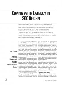
3) A method for using the specification also as a global checker to assure that the firmware and hardware implementations are compliant with the specification across all validation platforms (simulation, emulation, and silicon). The system architecture of iPave is illustrated in Figure 1. The top-right diagram denotes a system-level protocol, while the bottom box illustrates that the protocol on left is compared with the traces on the right as part of compliance check. Our approach to system-level specification consists of five main guidelines: ease of expression, support of gradual refinement, modularity (to enable parallel development by multiple teams while maintaining global consistency), well-defined formal semantics, and lastly, machine readability, to enable usage by downstream analysis tools. There may be various ways to meet these requirements– the most obvious one is to use a modeling language, e.g., SystemC [15], to develop executable specification that includes software/firmware/hardware partitioning and interface definitions [12]. Our experience at Intel over the years, however, is that the effort needed to develop executable specifications is too high for adoption by the architecture teams. A major reason is that, in contrast to performance models that are common in architecture design, the effort required of architects to develop fully detailed models for system-level protocols is simply too high to be practical. Another alternative is to use a formal-specification language, for example Promela, the input language of the SPIN model checker [20], or a declarative formalism such as TLA [23], in which the “contracts” between software, firmware, and hardware can be specified, c.f., [3]. The difficulty here is that such formalisms are accessible by a relatively small community of formal-methods experts. We choose a specification formalism and a capture method that we believe is significantly easier for architects to work with. The key idea is to use a workflow language for systemlevel protocol specification. Workflows are aimed at capturing business processes, where information or tasks are passed from one participant to another for action, according to a set of procedural rules [33]. In particular, Business Process Model and Notation (BPMN) is a graphical representation for specifying business processes in a business process model [36]. iPave uses a customized subset of BPMN, with a graphical representation entry in Microsoft Visio. In this graphical-entry format, called iFlow, a protocol specification is captured as a flow diagram in which the basic entities are tasks and transitions. Tasks denote individual operations/computation entities that occur as part of the protocol, while transitions govern the flow by defining the order in which the different tasks are executed. Transitions are enabled by guards and emit events. For example, an error-condition guard may trigger an exception-handling task, and the completion of that task may notify a completion event, which then allows normal processing to proceed. Since the protocols we want to specify are often concurrent, transitions can have multiple next tasks, which can be executed by multiple agents in the system. An example is provided in Figure 2.
Agent1
iPave Architecture
Agent2
SubSysIfc
T1
ToT1 T1
T2
Visual Front-End -- Spec Capture iFLOW
T2
T3
T1
MsgToT3
G1 T3 Input T4 T2 Output G2 FromG2
LSD: Formal logic model for describing tasks/transitions of a protocol and their dependencies
Intermediate Representation -- Logic Sequence Diagrams
MsgFromT2
Spec Exploration Capabilities Answer protocollevel queries using symbolic analysis
Compliance Validation Capabilities Agent1
Agent2
Sim/Emu HW and FW traces
SubSysIfc
T1
ToT1 T1
T2 T2
T3
MsgToT3
G1 T3 Input T4
? == T1
T2
Output G2 FromG2
MsgFromT2
Fig. 1.
iPave Architecture
For modularity, iFlow enables a flow model to be decomposed into main flow and subflows. The idea is that a task, say write, may be in turn modeled as a flow, in terms, say of tasks such as send, rcv, and ack. Thus, at the highest level of abstraction the user can refer to the write task, and then define its flow carefully in a separate subflow. Subflows are used in iFlow as syntactic sugar, reducing visual complexity. For the purpose of semantics, subflows can be eliminated by substitution. Thus, we do not discuss them further here. The goal of the visual interface is to facilitate vertical interaction with users, leading to shared understanding. Beyond merely shared understanding, using an iFlow model for specification analysis or compliance checking requires translating it into an intermediate representation. We first translate the diagram from its Visio representation into an XML representation. Then, the XML is translated into a semantics object, a logic sequence diagram, described in the next section. Philosophically, our approach is inspired by the “Design by Contract” approach, which requires software designers to define formal, precise and verifiable interface specifications for software components [25]. Our focus here is on SoCs, which can be partitioned along two dimensions, not only into components, but also into software, firmware, and hardware. Instead of using formal assertions, we advocate here the development of visual architectural specifications, which can then be compiled into assertions.
III. L OGIC S EQUENCE D IAGRAMS Visual formalisms offer an attractive user interface and have attracted a significant level of attention in the past 30 years [17]. The main benefit is that the formalism captures users’ intuition in a direct way, avoiding the need to learn a formal language. One of the most well known visual formalisms in computer science is that of Statecharts [16], which enriches the notion of state-transition diagrams with both horizontal and vertical decomposition. In spite of the intuitive clarity of visual formalisms, it is not uncommon for different users to have different understanding of the same visual object. Thus, visual formalisms must be intuitively transparent and at the same time have formal semantics. Analysis tools for these formalisms must be based on their formal semantics. It is important, therefore, not only to explain the intuition underlying a formalism, as in [16], but also its formal semantics. Defining rigorous formal semantics for a visual formalism can be highly nontrivial. Since the introduction of Statecharts in [16] lacked a formal semantics, there has been a proliferation of different proposals for such formal semantics, cf. [18], [19], [28]. As mentioned earlier, the iFlow formalism that we use in iPave is a fragment of BPMN. While BPMN is an industry standard, its semantics is not part of the standard and is a topic of ongoing research, cf. [10], [26], [37]. We chose here to define the formal semantics of iFlow in terms of an intermediate language, logic sequence diagrams (LSD), which, we believe, is of independent interest.
Fig. 2.
iFlow Example
To understand the intuition behind the LSD formalism, note first that our aim here is in specifying system-level workflows rather than state-based models. That is, we need a workflow formalism, rather than a state-based formalism, such as Statecharts. System-level workflows typically consist of tasks that need to be executed. Tasks lead to other tasks, until all tasks have executed. Tasks are persistent; they stay active until they complete. (See, for example, the transaction model in [24] or the flow models in [22], [27].) Transitions between tasks may be logically complex. A task t may fork into tasks t1 and t2 . Alternatively, the task t may transition into tasks t1 or t2 , depending on the state of the system. Transitions also may be constrained. The task t may not be able to start
until tasks t1 and t2 have completed (this is essentially a join). For example, we see in Fig. 2 how Task T 1 of Agent2 forks to start Tasks T 2 and T 3, which then join to start Task T 4. A workflow specification should describe how a piece of work, consisting of many tasks, is to be executed, that is, how the flow from task to task occurs. We have considered two existing formalisms for workflow description. Live Sequence Charts (LSCs) constitute a (visual) formalism to describe scenarios [8], and could be adapted for workflow description. But LSCs lack explicit constructs to express forks and joins, which are crucial for task synchronization. Petri Nets constitute a (visual) formalism to express choice, iteration, and concurrent execution. But this formalism
is too expressive for efficient automated analysis [9]. LSDs can be viewed as an abstract version of LSCs, augmented with constructs for forks and joins, inspired by Petri Nets. At the heart of LSCs is a language for describing scenarios, which is essentially that of Message Sequence Charts (MSCs). The main focus, however, in LSCs is on expressing relationship between scenarios, e.g., “Scenario A must be followed by Scenario B”. Our focus here is on scenarios and not on relationship between scenarios. We discuss the relationship between LSDs and MSCs below. The basic elements of an LSD are tasks, guards, and events. Tasks are the basic elements of work; a workflow consists of executing several tasks. A task may take some time to complete; once it is activated, it stays active until completion. Multiple tasks can be concurrently active. Guards are input of a workflow; they are abstract predicates (intuitively, referring to the state of an underlying system), for example, buffer_full. The goal of guards is to trigger transitions between tasks. Events are outputs of a workflow; they notify of transitions between tasks, for example msg_rcvd. Events are used in task synchronization; they should not be viewed as actual system messages. (See discussion of messages below.) The silent event τ is also allowed. While tasks are prolonged, tasks transitions, and, consequently, events, are instantaneous. A link is a pair (t, e) of a task t and event e, designating that t has started, emitting e. We abbreviate the link (t, τ ) by t. The dynamics of an LSD is defined in terms of transitions and constraints. Transitions describe the flow from completed tasks to new tasks. Each arrow in an iFlow diagram, for example, the transition from T 1 to T 2 in Subsyslfc in Fig. 2, corresponds to a LSD transition. A transition is a triple ht, g, βi, where t is a task, g is a guard, and β is a Boolean combination of links. The intention here is that t and g refer to the current time step, and β refers to the next time step. That is, when t is active and g becomes true, then t completes in this time step, and β must be satisfied in the next time step. Note that the task t stays active until the guard g signals that it has completed. For example, the transition ht, g, (t1 , e1 ) ∧ (t2 , e2 )i says that when the task t is active and the guard g becomes true, then t completes in the current time step (i.e., becomes inactive in the next time step), and forks off to both t1 and t2 , notifying e1 and e2 , respectively, in the next time step. In contrast, the transition ht, g, (t1 , e1 ) ∨ (t2 , e2 )i says that when the task t is active and the guard g becomes true, then t completes in the current time step and forks off to either t1 and t2 , notifying e1 or e2 , respectively, in the next time step. If β contains a disjunction, we call the transition a disjunctive transition. The Boolean combination β can also be true and false. Note that true is satisfied even by the empty set of links, and false is not satisfied by any set of links.2 Examples of Transitions: 0 • ht, g, t i – busy waiting: t stays active until g becomes true, at which point t completes and t0 starts (in the next 2 Thus, LSDs can be viewed as alternating automata [34] augmented with constraints.
time step). ht, g, t ∨ t0 i - stuttering: t can stay active even if g holds true, but it can also transition to t0 when g holds. • ht, g, truei – task completion: t completes when g holds, with no further transition. (Since true always holds, there is no further requirement.) • ht, g, falsei - failure: g is not allowed to hold when t is active; if g does hold while t is active, we have a deadlock, since false cannot be satisfied. Constraints force synchronization among tasks. Each join point in an iFlow diagram, for example, the join point of T 2 and T 3 before T 4 of Agent2 in Fig. 2, corresponds to a constraint. A constraint is a triple [t, g, γ], where t is a task, g is a guard, and γ is a Boolean combination of events. Such a constraint restricts transitions activating the task t. The intention here is that g and γ refer to the current time step, while t refers to the next time step. That is, t cannot become active in the next time step when g holds now, unless γ is satisfied now. For example, the constraint [t, g, e1 ∧ e2 ] says that when the guard g holds, the task t cannot start until events e1 and e2 have both been notified. In contrast, the constraint [t, g, e1 ∨ e2 ] says that when the guard g holds, the task t cannot start until either e1 or e2 have been notified. We discuss synchronous and asynchronous notification below. The rationale for expressing LSDs in terms of transitions and constraints is the goal of modularity. Consider the two transitions: ht, g1 , t1 i and ht, g2 , t2 i. They describe two different flows from the task t, one when g1 holds and one when g2 holds. Expressing these flows in terms of separate transitions enables us to think about flows in a modular way. Note that all rules are always “live”, and multiple rules can be enabled, i.e., have a true guard. Thus, if t is active and g1 and g2 are simultaneously true, then t forks to both t1 and t2 . The modularity of transitions and constraints come at a price, which is the possibility of conflicts. For example, suppose we have two transitions, ht1 , g1 , (t2 , e1 )i and ht2 , g2 , (t3 , e2 ))i, and a constraint [t2 , g1 , e2 ]. The constraint says that t2 is waiting for e2 to be notified, but the transition says that e2 is notified when t2 completes and t3 starts. Thus, we have a deadlock. Note that if no transition is enabled, then this is not a deadlock. If no transition exiting a task is enabled, then the task stays active. e.g., the transition ht, g, t0 i means that t stays active until g becomes true, at which point t transitions to t0 . Thus, if no transition is enabled, the workflow simply stutters, and all active tasks stay active. Note also that if no constraint constrains a task, then the task is unconstrained. That is, the constraint [t, g, γ] means that t waits for γ only if g holds; if the constraint is not enabled, then t is not constrained. One subtle point is the treatment of synchrony, where we think of a synchronous transition as “hand shaking”, and of asynchronous transition as “message passing”. Consider the constraint, [t, g, e1 ∧e2 ], which says that when g holds, t cannot start until e1 and e2 have been notified. Under synchronous semantics, e1 and e2 have to be notified simultaneously to enable the activation of t, e.g., the buffer_rcv task starts •
immediately after the write_op and buffer_rdy events are symultaneously notified. In contrast, under asynchronous semantics, e1 and e2 have to be notified earlier than the activation of t, e.g., the sender_rcv task need not synchronize with write_op and buffer_rdy events, it merely needs to wait for them to have happened. We allow both synchronous and asynchronous constraints in LSDs. (Asynchronous constraints can be eliminated by using dummy tasks that simply signal that certain events have been notified. We found it more natural to model asynchrony directly in terms of asynchronous constraints.) Definition 1: An LSD is a tuple (T, t0 , G, E, R, Cs , Ca ), where T is a set of tasks, t0 is an initial task, G is a set of guards, E is a set of events, R is a set of transitions, Cs is a set of synchronous constraints, and Ca is a set of asynchronous constraints. The semantics of LSDs is first defined over abstract states, which are elements of 2G ; that is an abstract state is simply a set of guards. A guard g holds in an abstract state a if g ∈ a. An abstract trace is a finite sequence of abstract states. A completed run of an LSD L = (T, t0 , G, E, R, Cs , Ca ) over an abstract trace a1 , . . . , an is an alternating sequence T0 , Λ1 , T1 , . . . , Tn of minimal sets of tasks and links, such that: • T0 = {t0 }: start with the initial task. • Tn = ∅: all tasks must complete. • Ti+1 is the projection on T of Λi+1 . • Transitions for tasks in Ti that are enabled by guards in ai are satisfied by Λi+1 . • Constraints for tasks in Ti+1 with respect to guards in ai are satisfied (synchronously or asynchronously, as discussed above). Finally, we define the semantics over a set K of concrete states, which are the states that appear in simulation traces. To relate concrete and abstract states, we need two abstraction functions. The guard abstraction function Γ maps K to 2G ; that is, every concrete state is mapped to the set of guards that hold in that state. The event abstraction function Υ maps K to 2E ; that is, every concrete state is mapped to the set of events notified in that state. A concrete trace is a finite sequence of concrete states. A completed run of an LSD L over a concrete trace k1 , ., kn is a completed run r of L on the abstract trace Γ(k1 ), . . . , Γ(kn ) such that events notified in r match the events in Υ(k1 ), . . . , Υ(kn ). Example 1: We now demonstrate how transitions and constraints can model parallel synchronization (for example, broadcast). • Transitions: – hstart, true, maintask ∧ task1 ∧ task2 ∧ task3i – hmaintask, g done, (finish, e done)i – hfinish, true, truei – htask1, true, task1 ∨ finish task1i – htask2, true, task2 ∨ finish task2i – htask3, true, task3 ∨ finish task3i – hfinish task1, true, truei
– hfinish task2, true, truei – hfinish task3, true, truei • Constraints: – [finish task1, true, e done] – [finish task2, true, e done] – [finish task3, true, e done] This flow starts with the task start and ends with the various ”finish” tasks, which complete with no further requirement. The task start forks into maintask, task1, task2 and task3. Then maintask completes when g done holds, and transitions to finish, notifying e done. The purpose of e done is to enable other tasks to complete; the notification of e done lets the individual tasks complete. Note that the relationship between LSDs and concrete traces can be viewed as a compliance relationship. A concrete trace Θ complies with an LSD L with respect to abstraction functions Γ and Υ if L has a completed run over Θ, denoted Θ |= L. Note that this means: • Absence of deadlock: enabled transitions can take place; • Absence of livelock: all tasks must complete; • Notified events match trace. The distinction between abstract and concrete semantics is meant to facilitate the application of LSDs at different levels of abstraction, for example, we can do compliance checking with respect to micro-architectural traces, RTL traces, and postsilicon traces. Obviously, different types of traces would use different notions of concrete states. Nevertheless, by defining the appropriate abstraction functions, we obtain concrete semantics and can check compliance of traces with LSDs. We now comment on the relationship between LSDs and MSCs. MSCs constitute a language for describing scenarios [31]. LSDs are more expressive and more abstract than MSCs. On one hand, we have abstracted away the agents that are integral to MSCs, as we do not find them to be essential. For example, the task Sender.write implicitly says that write is a task of Sender, without explicitly including agents in the formalism. (Note, however, that “swim lanes”, which represent agents, are allowed in iFlow for visual clarity.) On the other hand, the logical flow of tasks, as described by transitions and constraints is much richer in LSDs than in MSCs, and allows the expression of complex flows, including forks and joins. Note that there is no primitive in LSDs to denote a message. This is mainly because a message is not a primitive concept. Messages transmission may actually consists of several tasks, such as sending, transferring, receiving, acknowledging, and the like. Also, there might be multiple protocols for sending, e.g., messages can be delivered in-order, may be lost, and the like. There might also be other important attributes associated to messages, e.g., related to security. For these reasons, our approach to messages is that they should be modeled explicitly via existing LSD constructs. In the context of a specific application, a library of different message protocols may be modeled as a set of LSDs. While an LSD model can be built directly, using transitions
and constraints, this formalism is not meant to be used directly by iPave users, which are expected to be architects. Thus, in iPave LSDs are used purely as an intermediate formalism. The iFlow User Guide explains the semantics of the visual formalism in an intuitive fashion. The formal semantics of iFlow is embodied in the iFlow compiler, which compiles the XML representation of the diagram into an LSD. Nevertheless, we believe that LSDs provide a workflow formalism of independent interest, which may find usage in other applications. IV. S PECIFICATION A NALYSIS System-level protocols can be quite complex, leading to highly nontrivial iFlow specifications. Naturally, one would expect such specifications to contain errors. In model checking one compares an implementation to its specification [7], [32]; a mismatch suggests an error in the implementation or the specification. Thus, model checking is a way to debug together both implementation and specification. At the architectural specification phase, however, we do not yet have an implementation. Thus, specification analysis, or spec analysis, for short, emerges as an important design activity, analogous to the property-assurance activity for temporal specifications, cf. [14], [30]. The goal here is to enable architects to use spec analysis to improve specification quality through syntactic and semantic checking, as uncaught specification errors would likely lead to implementation errors with significant cost and quality implications. One challenge in spec analysis for LSDs is their level of abstraction. Recall that we intentionally allow for abstract guards and events, to allow for later semantic bindings at different level of abstraction. A consequence of that is that the model may be too abstract for meaningful analysis. To allow deeper spec analysis, iPave allows early semantic binding of guards and events over Boolean and integer variables. For example, the guard buffer_empty can be bound at the spec-analysis phase to the condition buffer_length=0, and the event buffer_write can be bound to the expression buffer_length++, which is an abbreviation for the condition buffer length0 = buffer length + 1. (We adhere to the convention that a primed variable refers to the value of the variable in the next time step.) Guards and events can be bound to transition conditions or assignments. Assignments can also be viewed as transition conditions (with a primed variables on the left), but the assignment form indicates that the assigned variables are viewed as state variable (see discussion below). This, in effect, can turn guards and events into transition conditions and actions. In addition to such semantic binding, the user can specify initial-state conditions. Figure 3 shows an example of an iFlow model with concrete actions and transition conditions. We now associate a finite-state machine (FSM) ML with an LSD L as follows. The FSM ML has variables of the following kinds: • Unassigned variables occurring in guard and event expressions: these are input variables of ML .
Assigned variables occurring in guard and event expressions: these are state variables of ML . • Boolean task variables: these are state variables of ML . • Boolean event variables: these are state variables of ML , with two variables es (synchronous) and (asynchronous) ea for each event e. The transition relation of ML is obtained from the transitions and constraints of L. Thus, a transition ht, g, βi, yields a transition relation that says that if t and g hold in a state s of ML , then β holds in the successor state s0 . Similarly, the constraint [t, g, γ] yields a transition relation that says that if g is true in a state s of ML , then t can be true in a successor state s0 only if γ holds in s. This translation from transitions and constraints to transition relation is not straightforward due to the intended semantics of tasks, which is that a task should be active only if is required to be active. Thus, at time 0 only the initial task is active. Then, in a transition from a state s to its successor s0 , a task t is active in s0 only if it is active in s and no transition enables it to complete, or if some transition requires it to be active in s0 and no constraint is blocking it from becoming active. We also need to deal with both synchronous and asynchronous constraints. When event e is notified, both es and ea become true, but es holds only for one time step, while ea stays true. Example 2: Consider Figure 3. The tasks t0,t1, and t2 are Boolean state variables. Initially, only t0 is true. Then t0 becomes false and t1 becomes true. Then either c1 > 2, in which case t1 becomes false and t2 becomes true, or c1 ≤ 2, in which case t1 stays true. (There are no constraints here to block transitions.) LSDs can be nondeterministic due to disjunctive transitions; that is, we allow a task t to transition to t1 or t2 . Nondeterminism is an important modeling construct, as it allows more abstract specifications [11]. Currently, iPave does not support disjunctive transitions for efficiency reasons, though users can simulate disjunctive transitions by introducing additional guards. Thus, instead of the transition ht, g, t1 ∨ t2 i, one can use two transitions: ht, p, t1 i and ht, ¬p, t2 i, for some appropriate guard p. As a result, the FSMs obtained from our LSD models are deterministic. This has implications for compliance checking, as we discuss below. iPave contains internally two compilers. The first compiler translates an iFlow model (in an XML representation) into an LSD. The LSD is the formal representation of the visual object. The second compiler translates the LSD into a symbolic FSM. The FSM is the representation used for spec analysis. Having a formally defined FSM means that we can apply various formal analysis tools to it. Two generic analyses are task-reachability analysis and termination analysis. In task reachability analysis we check that all tasks can be activated. We can do this analysis by model checking, for each task t, whether ML satisfied the temporal formula “always ¬t”. If the answer is positive, it means that the task t is not reachable. In termination analysis we check that there is a run of L where all tasks are completed. We do this analysis by model checking W whether ML satisfies the temporal formula “always t∈T t”. •
e2::c1-start
t1
c1 2
Concretized iFlow Example
If the answer is positive, it means that there is no run of L that reaches a point where no task is active. (In iFlow, users model flow termination using an end task.) More generally, the user can formulate other assertions and model check them against ML . For example, in the model of Figure 3, the user may want to check that the comparison of c1 and 2 yields both outcomes. We can check that by using two temporal assertions, “always c1 > 2” and “always c1 ≤ 2”, to see that both fail. Unlike task-reachability analysis and termination analysis, which are generic, assertion analysis is an art and depends on the creativity of the architect/validator to chose the right assertion. Of course, with very large iFlow models, specification analysis may run to the well-known “state-explosion problem” [6]. V. C OMPLIANCE C HECKING The main goal of iPave is the development of system-level specification to serve as a “contract” both horizontally (software, firmware, and hardware) and vertically (architecture, design, and validation). For such a contract, however, to have a tangible value in the development process it must be usable as a validation collateral. Without explicit use in the validation process, the development of the specification is viewed as a burden. Even if it is developed initially, it would not be kept up to date and would quickly become useless. Furthermore, the specification cannot be usable only in formal verification and must be usable in dynamic verification, since the latter constitutes the common approach to validation. Thus, our intention from the start was that we must be able to validate that the software, firmware, and hardware implementations are compliant with the specification throughout the lifetime of a product (pre and post silicon). This is done by means of trace checking: given a concrete trace Θ, does it comply with a given LSD L? This assumes a validation environment that generates traces, which is the major mode of validation in the computing industry.
We already discussed above that concrete traces can come at different levels of abstraction, and it is up to the validator to define the proper mapping between the abstract guards and events of an LSD and the concrete states of the trace. There is, however, another mismatch between traces and LSDs that must be overcome. A trace is generated by the validation environment by simulating the implementation according to some complex scenario. An LSD, in contrast, describes a protocol for one work item, for example, user_authenticate. The trace generated by the simulation may contain, however, multiple work items. It may even contain multiple instances of the same work item, say, instances of user_authenticate. Thus, we need a mechanism for extracting a slice from a simulation trace corresponding to a single instance of a work item. This slicing mechanism is not part of iPave as it is highly dependent on the format of the simulation trace. We do assume that this format contains enough information to indicate the beginning and end of the execution of an instance work item. For example, the trace may contain the annotation begin user-authenticate id=x ... end user-authenticate id=x Such an annotation not only indicates the beginning and end of an instance of user_authenticate, but also, by means of an id, it indicates which points between the beginning and the end belong to the execution of this instance of user_authenticate. Thus, we assume that a concrete trace Θ has been extracted, and we need to check that it complies with a given LSD L.
In general, compliance checking may be a nontrivial problem. Theorem 1: Trace checking with respect to LSD is NPcomplete. Proof Sketch: In NP: Guess an alternating sequence T0 , Λ1 , T1 , . . . , Tn of sets of tasks and links and check that it is a completed run of L over Θ. NP-hard: We can reduce graph 3-coloring to trace checking. The LSD contains tasks for node coloring and edge coloring. For each node we have a transition that colors the node in one of three colors, chosen nondeterministically (using disjunction). For each edge we have a constraint that says that the edge-coloring can be activated only if its two end nodes have not been colored with the same color. The trace simply contains the list of nodes and edges, but without specifying the choice of colors. Thus, in general, trace checking has to be done using bounded model checking techniques [5]. Given a trace Θ of length k, we can unroll the FSM ML k times, where the values of the guards and events at time i are given by Θi , the i-th sate of Θ. (Thus, only task variables remain free.) The resulting formula is fed to a SAT solver to check satisfiability. As noted above, however, iPave does not allow disjunctive transitions, which means that we do not have nondeterminism here. The intuition is that the trace contains all information required to resolve nondeterminism. That is, if instead of the transition ht, g, t1 ∨ t2 i, one used two transitions, ht, p, t1 i and ht, ¬p, t2 i, then the trace should tell us whether p or ¬p holds, resolving whether t should transition to t1 or t2 . Thus, we can check compliance by simulating the LSD L against the trace Θ. At point i of the simulation we have a set Ti of active tasks. We then consult Θi to see which guards are true and, consequently, which transitions are enabled. The enabled transitions yield a set Λi+1 of links, whose projection on T yields Ti+1 . We also need to check that no transition fails, all constraints are satisfied, and the tasks in Ti+1 are allowed to be activated (no deadlock). We also check that all notified events are reflected in Θ. Finally, we check that Tk is empty (all tasks have been completed). VI. R ESULTS AND D ISCUSSION As proof of concept, we ran a pilot in which we applied the iPave framework to graphics-microcontroller firmware. An iFlow model was constructed in collaboration with the project architects and then used for the verification of the firmware in an existing validation environment (with stubs for hardware and software). The model had four agents and 50 tasks, and was subjected to 250 different tests. Compliance analysis found ten bugs/gaps in the firmware and its validation environment, related to issues of concurrency, race conditions, event order, redundant or missing events, uncompleted tasks, and the like. Several of these problems reflected highly intricate protocol behavior, arising from complex interactions
between different hardware and firmware agents. Many of these problems were not caught by regular simulation due to lack of appropriate assertions, as assertions used as simulation checkers are often local, and do not express global properties, in contrast to our system-level iFlow models. (We also planned to validate the graphics hardware against the same iFlow specification, since it serves as a contract between firmware and hardware, but this activity has not yet been pursued, due to limited resources in the design team.) iPave has been successfully used to validate other systemlevel protocols, in security, resets, and power management. In one instance, the iFlow model had 172 tasks, and was concretized with 18 Boolean variables and 34 integer variables. Several gaps and errors in the architecture have been identified, including five concurrency bugs between threads that were found during spec analysis. More importantly, the counterexamples found in the analysis of the iFlow models helped the users to understand the protocols better and gain higher confidence. It would have been extremely difficult to find these bugs without first carefully constructing iFlow models for these protocols. We believe that this work represents a paradigm shift in design methodology by blurring the lines between architecture and validation. Traditionally, architects have resisted adoption of formal-method tools, which they found “alien” to their culture. Using a visual formalism meant that the validation tool builders are adapting themselves to the architect’s culture, rather than the other way around. Architects do traditionally use visual representations, but those usually have no formal meaning; as a result, they are used only in an informal way. Having the iFlow visual formalism means that these visual representations can be expressed using the iPave framework and become a design and validation collaterals. As such, there is now motivation for keeping these models alive, continually updated, throughout the lifetime of a design project and beyond. The gaps between architecture, design, and validation have always been a key source of design errors that are late to find, delaying time to market, increasing cost, and reducing quality. We believe that visual formalisms may be the key to narrowing these gaps. Beyond the specific formalism and analysis techniques described in this paper, we believe that exploring the role of visual formalisms in design methodology is an important research area. While earlier works studied visual specification formalisms, cf., [13], the focus here on formalisms for architectural specification is novel and significant. Acknowledgements: We are grateful to Dror Caspi, Baruch Chaikin, Alan Curtis, Jeff Frizzell, Sava Krstic, Ajay Ramakrishnan, and Shan Reddy for contributions to the iPave framework.
R EFERENCES [1] Y. Abarbanel, E. Singerman, and M.Y. Vardi. Validation of SoC firmware-hardware flows: Challenges and solution directions. In Proc. 51st Annual Design Automation Conference, pages 2:1–2:4. ACM, 2014. [2] M. Martin B. Bailey and A. Piziali. ESL design and verification: a prescription for electronic system level methodology. Morgan Kaufmann, 2010. [3] B. Batson and L. Lamport. High-level specifications: Lessons from industry. In Proc. 1st Int’l Symp. on Formal Methods for Components and Objects, volume 2852 of Lecture Notes in Computer Science, pages 242–261. Springer, 2002. [4] L. Bening and H. Foster. Principles of verifiable RTL design – a functional coding style supporting verification processes. Springer, 2001. [5] A. Biere, A. Cimatti, E.M. Clarke, M. Fujita, and Y. Zhu. Symbolic model checking using SAT procedures instead of BDDs. In Proc. 36st Design Automation Conf., pages 317–320. IEEE Computer Society, 1999. [6] E.M. Clarke, O. Grumberg, S. Jha, Y. Lu, and H. Veith. Progress on the state explosion problem in model checking. In Informatics - 10 Years Back. 10 Years Ahead, volume 2000 of Lecture Notes in Computer Science, pages 176–194. Springer, 2001. [7] E.M. Clarke, O. Grumberg, and D. Peled. Model Checking. MIT Press, 1999. [8] W. Damm and D. Harel. Lscs: Breathing life into message sequence charts. Formal Methods in System Design, 19(1):45–80, 2001. [9] M. Diaz. Petri nets: fundamental models, verification and applications. John Wiley & Sons, 2013. [10] R. Dijkman, M. Dumas, and C. Ouyang. Semantics and analysis of business process models in BPMN. Information and Software Technology, 50(12):1281–1294, 2008. [11] E.W. Dijkstra. Cooperating sequential processes. Springer, 2002. [12] J. Falk, C. Zebelein, C. Haubelt, J. Teich, and R. Dorsch. Integrating hardware/firmware verification efforts using SystemC high-level models. In Methoden und Beschreibungssprachen zur Modellierung und Verifikation von Schaltungen und Systemen (MBMV), pages 137–146. Fraunhofer Verlag, 2010. [13] K. Fisler. Extending formal reasoning with support for hardware diagrams. In 2nd Int’l Conf. on Theorem Provers in Circuit Design - Theory, Practice and Experience, Lecture Notes in Computer Science 901, pages 298–303. Springer, 1994. [14] D. Fisman, O. Kupferman, S. Seinvald, and M.Y. Vardi. A framework for inherent vacuity. In Haifa Verification Conference, volume 5394 of Lecture Notes in Computer Science, pages 7–22. Springer, 2008. [15] T. Groetker, S. Liao, G. Martin, and S. Swan. System Design with SystemC. Springer, 2002. [16] D. Harel. Statecharts: A visual formalism for complex systems. Sci. Computer Prog., 8:231–274, 1987. [17] D. Harel. On visual formalisms. Communications of the ACM, 31(5):514–530, 1988. [18] D. Harel and A. Naamad. The statemate semantics of statecharts. ACM Transactions on Software Engineering and Methodology, 5(4):293–333, 1996. [19] D. Harel, A. Pnueli, J.P. Schmidt, and R. Sherman. On the formal semantics of statecharts. In Proc. 2nd IEEE Symp. on Logic in Computer Science, pages 54–64. IEEE Computer Society, 1987. [20] G.J. Holzmann. The Spin Model Checker:primer and reference manual. Addison-Wesley, 2004. [21] A. Horn, M. Tautschnig, C.G. Val, L. Liang, T. Melham, J. Grundy, and D. Kroening. Formal co-validation of low-level hardware/software interfaces. In 13th Int’l Conf. Formal Methods in Computer-Aided Design, pages 121–128. IEEE, 2013. [22] S. Krstic, J. Yang, D.W. Palmer, R.B. Osborne, and E. Talmor. Security of SoC firmware load protocols. In 2013 IEEE Int’l Symp. on HardwareOriented Security and Trust, pages 70–75. IEEE, 2014. [23] L. Lamport. Specifying Systems: The TLA+ Language and Tools for Hardware and Software Engineers. Addison-Wesley, 2002. [24] Y. Mahajan and S. Malik. Automating hazard checking in transactionlevel microarchitecture models. In Proc. 7th Int’l Conf. Formal Methods in Computer-Aided Design, pages 62–65. IEEE, 2007. [25] B. Meyer. Applying “design by contract”. Computer, 25(10):40–51, 1992.
[26] O. Nicolae, M. Cosulschi, A. Giurca, and G. Wagner. Towards a BPMN semantics using uml models. In Proc. Business Process Management Workshop, pages 585–596. Springer, 2009. [27] J. O’Leary, M. Talupur, and M.R. Tuttle. Protocol verification using flows: An industrial experience. In Proc. 9th Int’l Conf. on Formal Methods in Computer-Aided Design, pages 172–179. IEEE, 2009. [28] A. Pnueli and M. Shalev. What is in a step: On the semantics of statecharts. In Proc. Int’l Conf. on Theoretical Aspects of Computer Software, Lecture Notes in Computer Science 526, pages 244–264. Springer, 1991. [29] S. Ray, J. Bhadra, M.S. Abadir, and L.-C. Wang. Guest editorial: Test and verification challenges for future microprocessors and SoC designs. J. Electronic Testing, 29(5):621–623, 2013. [30] K.Y. Rozier and M.Y. Vardi. LTL satisfiability checking. Int’l J. on Software Tools for Technology Transfer, 12(2):1230–137, 2010. [31] E. Rudolph, P. Graubmann, and J. Grabowski. Tutorial on message sequence charts. Computer Networks and ISDN Systems, 28(12):1629– 1641, 1996. [32] K. Schneider. Verification of Reactive Systems: Formal Methods and Algorithms. Springer, 2004. [33] A. Sharp and P. McDermott. Workflow modeling: tools for process improvement and applications development. Artech House, 2009. [34] M.Y. Vardi. Alternating automata and program verification. In Computer Science Today –Recent Trends and Developments, volume 1000 of Lecture Notes in Computer Science, pages 471–485. Springer, 1995. [35] M.Y. Vardi. Formal techniques for SystemC verification. In Proc. 44th Design Automation Conference, pages 188–192. IEEE, 2007. [36] S.A White. BPMN modeling and reference guide: understanding and using BPMN. Future Strategies Inc., 2008. [37] P.Y.H. Wong and J. Gibbons. A process semantics for BPMN. In Formal Methods and Software Engineering, pages 355–374. Springer, 2008.