Full Fuzzy-Logic-Based Vector Control for Permanent Magnet Synchronous Motors Jae-Sung Yu1, Byoung-Kuk Lee1, Chung-Yuen Won1, and Dong-Wook Yoo2 1
Department of Information & Communication Engineering, SungKyunKwan University, 300, chunchun-dong, Jangan-gu, Suwon, Kyunggi-do, 440-746, Korea
[email protected],
[email protected],
[email protected] http://icc.skku.edu/~won 2 Power Electronics Group, Korea Electrotechnology Research Institute, P.O.BOX 20, Changwon, 641-120, Korea
[email protected]
Abstract. This paper proposes a full fuzzy-logic-based vector control for a permanent-magnet synchronous motor (PMSM). The high-performance of the proposed fuzzy logic control (FLC)-based PMSM drive are investigated and compared with the conventional proportional-integral (PI) controller at different conditions, such as step change in command speed and load, and etc. In the experimental results, the FLC is employed in the speed and current controller. The comparative experimental results show that the FLC is more robust and, hence, found to be a suitable replacement of the conventional PI controller for the high-performance drive system.
1 Introduction The induction motor has been used for the conventional high-performance drive system because of its simple and rugged construction. However, an induction motor has limitations on compactness and torque due to power factor and efficiency decrease as the number of pole increases. Recently, PMSM is more used in the drive system due to the advantage that the PMSM is smaller and more compact than the induction motor. In this paper, vector control algorithm is adopted for the high performance control of PMSM. Conventionally, in speed and current controller, PI controller is employed. However, the fixed-gain controllers are very sensitive to parameter variations, load disturbances, and etc. Thus, the controller parameters have to be continually adapted. This problem can be solved by several adaptive control techniques, such as Model Reference Adaptive Control (MRAC) [1], Sliding-Mode Control (SMC) [2], Variable Structure Control (VSC) [3], self-tuning PI controllers [4], and etc. The design of all of the above controllers depends on the exact mathematical model of the system. However, it is often difficult to develop an accurate system mathematical model due to unknown load variation, unknown and unavoidable parameter variations due to saturation, temperature variations, and system disturbances. In order to overcome the above problems, recently, the fuzzy logic controller is employed for motor control purpose [5],[6],[7]. B. Gabrys, R.J. Howlett, and L.C. Jain (Eds.): KES 2006, Part III, LNAI 4253, pp. 875 – 882, 2006. © Springer-Verlag Berlin Heidelberg 2006
876
J.-S. Yu et al.
FLC is basically nonlinear and adaptive controller, which gives robust performance for a linear or nonlinear plant with parameter variations [8]. As it mentioned above, even if a plant model is well-known, there may be parameter variation problems, an accurate mathematical model is difficult to find. However the FLC system essentially embeds the experience and intuition of a human plant operator, and sometimes those of a designer and/or researcher of a plant. Recently, the high-speed digital signal processor (DSP) has been widely used for high performance, which makes it possible to implement more advanced control algorithms like FLC [9]. This paper presents a drive system using FLC both in the speed controller and current controller. The complete vector control scheme of drive systems incorporating the FLC has been successfully implemented in real time using digital signal processor (DSP) TMS320VC33. The performances of the proposed drive system have also been compared with the conventional PI controller in the experiment.
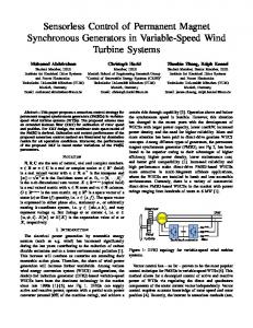
2 Structure of FLC Fig. 1 shows the block diagram of the FLC for the PMSM. The FLC is divided into four modules : fuzzifier, knowledge base, fuzzy inference engine and defuzzifier. This chapter explains the structure of speed fuzzy controller. The structure of current controller is similar to speed fuzzy controller.
Fig. 1. Block diagram of FLC
2.1 Input and Output Variables To compose the FLC for the PMSM, first of all, input and output variables of the FLC have to be determined. In this paper, in the speed controller, the speed error and the rate of change of the speed error are considered as the input crisp variables, which are defined as,
Δe(n) = Δωr (n) − Δωr (n − 1) Δωr (n)
= ωr* (n) − ωr (n)
(1) (2)
The output of the FLC is the torque-producing current and is defined as, iqse* (n) = iqse* (n − 1) + η ⋅ Δiqse (n)
(3)
Full Fuzzy-Logic-Based Vector Control for PMSM
877
where, Δiqse (n) is the inferred change of the torque-producing current by the FLC at the n-th sampling time, and η is the gain factor of the FLC. In the current controller, the inputs variables are the current error and the rate of change of the current error and the output variable is voltage reference. 2.2 Membership Functions
In the FLC, input and output variables are expressed by linguistic variables, which are represented by a membership function. Linguistic variables are defined as fuzzy subsets. In this paper, seven fuzzy subsets are chosen for input and output variables. : Negative Big (NB), Negative Medium (NM), Negative Small (NS), Zero (ZE), Positive Small (PS), Positive Medium (PM), Positive Big (PB). In order to compose above membership function, the membership function of triangular type is adopted for the error input of FLC and the singleton type is adopted for the output of FLC. Fig. 2 shows the membership function adopted in this paper.
(a) triangular type
(b) singleton type Fig. 2. Membership functions. (a) is the input membership function with respect to error and change error of FLC, respectively. (b) is the output membership function of FLC.
2.3 Derivation of Control Rules
Control rules are derived by the experience or the knowledge of experts. The fuzzy rules are in the form
Ri : IF Δω r is Ai and Δe is Bi , THEN iqse* is Ci where, Ai , Bi are the fuzzy subset, and Ci is a fuzzy singleton. The derivation of the fuzzy control is based on the following criteria : 1) When the speed of PMSM is far from the reference, the change of torqueproducing current must be large so as to bring the speed to the reference.
878
J.-S. Yu et al.
2) When the speed of PMSM is approaching the reference, the small change of torque-producing current is necessary. 3) When the speed of PMSM is near the reference and is approaching it rapidly, torque-producing current must be kept constant so as to prevent overshoot. 4) When the speed of PMSM reaches the reference and speed is still changing, torqueproducing current must be changed a little bit to prevent the output from moving away. 5) When the speed of PMSM reaches the reference and the speed is in steady state, torque-producing current remains unchanged. 6) When the speed of PMSM is above the reference, the sign of change of torqueproducing current must be negative. According to above criteria, the rule table shown in Table 1 is derived. Table 1. Fuzzy-Rule-Based Matrix in the speed controller e* Δiqs ( n)
NB NM NS Δ e (n ) ZE PS PM PB
NB -60 -60 -60 -60 -40 -20 0
NM -60 -60 -60 -40 -20 0 20
NS -60 -60 -40 -20 0 20 40
Δω r (n) ZE PS -60 -40 -40 -20 -20 0 0 20 20 40 40 60 60 60
PM -20 0 20 40 60 60 60
PB 0 20 40 60 60 60 60
Input linguistic variables are converted to output singleton variables through the fuzzy inference engine and the rule base. The inference result of each rule consists of two parts, a weighting factor and the degree of the torque-producing current, Ci . For example, if Δωr is 35[rad/sec] and Δe is 12[rad/sec2], respectively, Δωr belongs to PS, PM and Δe belongs to ZE, PS. Accordingly, following four rules are possible, e is 20[A]. 1) IF Δω r is PS and Δe is ZE, THEN Δiqs
e 2) IF Δω r is PS and Δe is PS, THEN Δiqs is 40[A]. e 3) IF Δω r is PM and Δe is ZE, THEN Δiqs is 40[A]. e is 60[A]. 4) IF Δω r is PM and Δe is PS, THEN Δiqs
And, by min operation, the weighting factor is obtained.
ωi = min {μe (Δω r ), μce (Δe)}
(4)
Finally, the inference results are obtained by following equation. zi = ωi Ci
(5)
Full Fuzzy-Logic-Based Vector Control for PMSM
879
2.4 Defuzzification
The inferred results should be converted to the Crisp set. In this paper, the center of gravity defuzzification is used. The output function is given as[11], 4
∑ω C i
e Δiqs
=
i
i =1 4
∑ω
(6)
i
i =1
According to (8), e Δiqs =
20 × 0.4 + 40 × 0.6 + 40 × 0.166 + 60 × 0.166 = 36.486[ A] 0.4 + 0.6 + 0.166 + 0.166
(7)
and the change of the torque-producing current at this sampling time is e* e* e iqs (n) = iqs (n − 1) + η ⋅ Δiqs ( n)
(8)
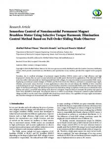
3 Drive Systems Using Fuzzy Logic Controller The proposed method is confirmed by experimental results. Experiments were performed on a motor-generator set with a 13.3- kW PMSM and a 16.8- kW dc motor.
Fig. 3. Control block diagram of PMSM using FLC
880
J.-S. Yu et al.
Fig. 3 shows a control block diagram of PMSM using FLC in the vector control system. This system has a two control loops; one is for speed controller, the other for current controller. The fuzzy inference of the speed controller make a torque reference through speed error and the fuzzy inference of the current controller make a voltage reference through an output of the speed controller. The SVPWM is applied to generate PWM signals, which will fire the power semiconductor devices of the three-phase inverter to produce the actual voltages to the motor.
4 Experimental Results Figs. 4 (a) and (b) show the experimental speed and load responses of the drive system using the PI controller, respectively. Figs. 5(a) and (b) show the experimental results with respect to speed and load response of the drive system using the FLC, respectively. Fig. 4(a) shows the response characteristic when reference is changed from 150[rpm] to 150 [rpm] and back to -150[rpm]. It is spent about 200[ms] to reach to the steady state. As the transient state, PMSM generates a maximum torque. Fig. 4(b) shows the response characteristics of PMSM when reference is 100[rpm] and 330[Nm] (50% of rated torque) is applied in arbitrary time. Load is applied during about 6[sec]. It is confirm that a speed error is about 10[rpm] and 0.7[sec] is spent to reach to the steady state. The conditions of Figs. 5(a) and (b) are the same as Figs. 4(a) and (b). Fig. 5(a) show that it is spent 200[ms] to reach to the steady state which is the same as result of PI controller. In Fig. 5(b), there is nearly no speed error. The comparative experimental results of Fig. 4(b) and Fig. 5(b) show that the FLC is more robust to a load torque.
(a) Speed reversal characteristic (-150[rpm]→+150[rpm] →-150[rpm]) (Speed : 1[V] →50[rpm], Current : 1[V] →5[A])
(b) Load response characteristic (Speed Ref : 100[rpm], Load : 330[Nm]) (Speed : 1[V] →20[rpm],Current : 1[V] →5[A])
Fig. 4. Response characteristics of PI controller in respect of speed reversal and sudden load change at 100[rpm]
Full Fuzzy-Logic-Based Vector Control for PMSM
(a) Speed response characteristic (-150[rpm]→+150[rpm] →-150[rpm]) (Speed : 1[V] →50[rpm], Current : 1[V] →5[A])
881
(b) Load response characteristic (Speed Ref : 100[rpm], Load : 330[Nm]) (Speed : 1[V] →20[rpm], Current : 1[V] →5[A])
Fig. 5. Response characteristics of FLC in respect of speed reversal and sudden load change at 100[rpm]
5 Conclusion A FLC-based vector control of PMSM has been presented in this paper. Since exact system parameters are not required in the implementation of the proposed controller, the performance of the drive system is robust, stable, and insensitive to parameters and operating condition variations. In order to verify the superiority of the FLC, a conventional PI-controller-based PMSM drive system has also been experimented. From the comparative experimental results, it is confirmed that the proposed FLC is more than the PI controller in case of load disturbance.
References 1. H. Sugimoto and S. Tamai.: Secondary resistance identification of an induction motor applied model reference adaptive system and its characteristics. IEEE Trans. Industry Applications., Vol. IA-23, pp. 296–303, Mar./Apr.1987. 2. C. Y. Won and B. K. Bose.: An induction motor servo system with improved sliding mode control, in Proc. IEEE IECON’92, pp. 60–66 3. T. L. Chern and Y. C. Wu.: Design of integral variable structure controller and application to electrohydraulic velocity servo systems, in Proc. Inst. Elect. Eng., Vol. 138, no. 5, pp. 439–444, Sept. 1991. 4. J. C. Hung.: Practical industrial control techniques, in Proc. IEEE IECON’94, pp. 7–14. 5. I. Miki, N. Nagai, S. Nishiyama, and T. Yamada.: Vector control of induction motor with fuzzy PI controller, in IEEE IAS Annu. Rec., 1992, pp. 464–471. 6. Y. Tang and L. Xu.: Fuzzy logic application for intelligent control of a variable speed drive, IEEE Trans. Energy Conversion, Vol. 9, pp. 679–685, Dec. 1994. 7. E. Cerruto, A. Consoli, A. Raciti, and A. Testa.: Fuzzy adaptive vector control of induction motor drives, IEEE Trans. Power Electron., Vol. 12, pp. 1028–1039, Nov. 1997. 8. Bimal K. Bose.: Modern Power Electronics and AC Drives., Prentice Hall PTR, 2002. 9. Y.M.Lee, J.K.Kang, S,K,Sul.: Acceleration Feedback Control Strategy for Improving Riding Quality of Elevator System, IEEE IAS Conf. Rec., pp.1375-1379, 1999.
882
J.-S. Yu et al.
10. Wing-Chi So, Chi K, Tse, Yim-Shu Lee.: Development of a Fuzzy Logic Controller for DC/DC Converters : Design, Computer Simulation, and Experimental Evaluation, IEEE Trans on Power Electronics, Vol11, no. 1, pp.24-32, Jan.1996. 11. H.T.Nguyen, M.Sugeno, R.Tong, and R.R.Yager.: Theoretical Aspects of Fuzzy Control. New York:Wiley, 1995