Full-Speed Field-Programmable Memory BIST Architecture Xiaogang Du, Nilanjan Mukherjee, Wu-Tung Cheng Mentor Graphics, 8005 SW Boeckman Rd, Wilsonville, OR 97070
[email protected] Sudhakar M. Reddy ECE Dept., the University of Iowa, Iowa City, IA 52242
Abstract A full-speed field-programmable memory BIST controller is proposed. The proposed instruction and architecture designs enable full-speed operation of not only March algorithms but also some non-linear algorithms that are becoming more and more important in modern memory testing, diagnosis, and failure analysis.
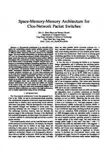
1. Introduction As current System-on-Chip (SOC) designs become memory intensive, the manufacturing yield of such devices greatly depend on the yield of embedded memories. Smaller feature sizes and increasing real estate occupied by memories on a chip is resulting in an enormous critical area that is conducive to a large number of potential defects. The ITRS 2000 Roadmap (Figure 1) depicts rapid increase in the percentage of chip area occupied by memories in a design and the increasing trend predicted for the next decade. 100 90 80 70 60 50 40 30 20 10 1999 % Area
2002
2005
2008
2011
2014
Figure 1: Chip area occupied by memories Many fault models and test algorithms have been developed to detect defects in a memory [1]. Some of these algorithms are already being used extensively in practice
Paper 45.3
while some others are being adopted rapidly to improve defect coverage. In addition, BIST has become an attractive alternative for implementing such algorithms, offering the benefits of high fault coverage, full speed test application, extensive diagnostics, and on-chip test hardware thereby eliminating the need for sophisticated ATE. Traditionally, BIST controllers are capable of running the test algorithms in a pre-specified sequence during manufacturing test. Since these controllers are customized and hardwired for a given memory architecture and a pre-defined set of algorithms, the area overhead is low and tests can be applied at-speed. One of the major disadvantages of hardwired controllers is their limited flexibility. With rapid changes in technology, it is becoming extremely difficult to predict the defect types that could manifest during the manufacturing process. Similarly, often a chip or its later revisions stay long enough to be manufactured with different technology nodes. Under such circumstances, test algorithms that would work well for a certain technology for which the controller was designed may no longer work when manufactured using the next technology node. Consequently, there is an increasing need for a programmable BIST solution that would allow certain degree of flexibility to modify test programs at run time. This would help analyzing the failing parts during production test, identifying of the defects that are escaping, re-designing the existing algorithms or introducing new algorithms, and use it to reduce the test escapes. It also aids in failure analysis thereby speeding up the ramp up period of a new process. Specifically, the following summarizes some of the advantages of a programmable BIST controller: a. Flexibility to create different data backgrounds, addressing schemes, and test algorithms. The experiments in [2] demonstrate that the fault coverage depends heavily in using different combinations of data backgrounds and addressing schemes. b. Flexibility to accommodate new test algorithms developed for newly identified defects. This helps in
INTERNATIONAL TEST CONFERENCE 0-7803-9039-3/$20.00 © 2005 IEEE
1
improving the test quality, which is specially useful for military, medical, and automotive applications. c. Helping failure analysis thereby expediting the yield learning period of a fabrication process. d. Allows better management of test time as different sets of algorithms can be applied at different phases of test, such as wafer sort, burn-in test, parametric, package, etc. Traditionally, March algorithms have been widely used for testing memories because of their high fault coverage and linear complexity in test application time. However, in such cases, algorithms that are non-linear in nature are used to improve the defect coverage and diagnostic capability [1, 3, 4]. One such algorithm is GALPAT, which can detect address faults, stuck-at faults, transition faults, and coupling faults in a memory array. Although GALPAT is of quadratic complexity it is becoming a requirement, particularly for failure analysis when being manufactured at sub 100nm technology nodes. Some variations of GALPAT that are of lesser complexity such as GALROW, GALCOL, butterfly and sliding diagonal are also used. In addition, only the tests applied at the rated speed of the memories can detect some defects. For this reason, full-speed BIST has become an important requirement for achieving high defect coverage. Summarizing, a flexible and high-performance programmable memory BIST solution should have the following features: a. The architecture should be able to handle different address configurations, different data backgrounds, and any combination of operations represented in a test step. b. The architecture should not only run March algorithms but should also be capable to run complex algorithms that may have two levels of nested loops mentioned above. These loops can have different address configurations and can be either dependent or independent of one another. c. It should support full-speed execution of test steps. This allows detection of speed related defects, which would otherwise escape a test. d. Diagnostics should not affect full-speed testing. e. Finally, the area overhead should be low. As an additional requirement, the architecture should be modular in nature such that hardware supporting different classes of algorithms is added as needed during the synthesis of the controller. Therefore, we should be able to control the capability of the controller. The remainder of the paper is organized as follows. In Section 2, a review of existing literature on fieldprogrammable memory BIST designs is included. Section 3 describes the proposed programmable memory BIST architecture. Section 4 includes experimental results. Section 5 concludes the paper.
Paper 45.3
2. Previous Works Programmable memory BIST controllers can be broadly classified into two categories [11]: FSM-based and micro-code based. In an FSM-based programmable BIST controller, pre-selected elements representing different combination of memory operations from conventional March algorithms are encoded. Subsequently, any March algorithms created during run-time must be based on the pre-selected element set. Whereas, in a micro-code based programmable BIST controller, instead of encoding March elements, the basic memory operations are encoded. As a result, this architecture can implement any March algorithm given there is enough storage for all the instructions. In summary, an FSM-based programmable BIST controller usually has less area overhead but relatively less flexibility, while a micro-coded programmable BIST controller provides more flexibility but with a higher area overhead. Several programmable memory BIST architectures are proposed in the literature. We will give brief overview of some typical designs. In [5, 6], an FSM-based programmable memory BIST controller is developed for DRAM testing. A test instruction contains read/write operations, address order, data background, and RAM access mode (row scan, column scan, page-mode column scan or refresh). At a macro-level, different steps of conventional March algorithms are encoded. The micro-coded BIST controller in [7] was also developed for DRAM testing. The program memory is composed of a ROM and a register array. The ROM contains algorithms that are commonly used and the register array can be loaded with new test algorithms. From the instructions defined, it appears that the controller cannot support certain complex algorithms like galloping/walking, butterfly, sliding diagonal and test for address decoder open faults. The micro-coded BIST controller in [8] was developed for static RAMs. Instructions are inserted between operations to specify data background and jump instructions are used to specify loop jump addresses. Therefore, the controller is unable to test memory at fullspeed. In addition, the controller can support March algorithms only. In [11], both an FSM based BIST controller and a micro-code based BIST controller are described. However, the proposed designs have limited flexibility. All the proposed architectures mentioned above primarily support March or March-like algorithms, which results in low flexibility. Besides the above BIST architectures, there is another programmable architecture worth mentioning. It refers to programmability at controller generation time and is referred to as User Defined Algorithm (UDA) [9]. UDA allows users to define
INTERNATIONAL TEST CONFERENCE
2
Table 1: Algorithm instructions [8] EBL End of Base Loop
[7] BBL Begin of Base Loop
[6] ELL End of Local Loop
[5] BLL Begin of Local Loop
B Base
L Local
[4:3] B+1 Base + 1
one’s own March algorithms in terms of test steps, address sequences, and data backgrounds. As mentioned earlier, the hardware is generated after users define algorithms and is hard-wired to execute the same. Therefore, the algorithms cannot change during run time. In the following section, the details of a flexible highperformance programmable memory BIST controller design are described.
3. Overview of the Architecture Figure 2 shows the top-level architecture of the proposed field-programmable memory BIST (FP-MBIST). Latency Adjuster Instruction Instruction Buffer and Memory Decoder
Control Gen Addr Gen
Memory Under Test
Data Gen
ORA PC Gen DIAG ATE
Figure 2 Top-level design The architecture consists of an instruction memory, instruction decoder, program counter generator, control signal generator, address generator, data generator, latency adjuster, output response analyzer and a diagnostic monitor. The instruction memory is composed of several registers. The size of an instruction word is 9 bits. The instructions can be loaded from ATE using a load clock, which is usually slower than the system clock. The program counter (PC) selects the instructions in the instruction memory to be loaded into the instruction buffers through multiplexors.
Paper 45.3
B-1 Base - 1
[2] 0/1 Data or Data Inverse
[1] R/W Read or Write
[0] A Algorithm Instruction (=1)
The instruction decoder decodes configuration instructions read from the instruction memory and algorithm instructions read from the instruction buffers. The PC generator generates three addresses accessing the instruction memory, base and local loop buffers. The control signal generator generates read/write signal to the memory under test. The address generator generates valid address sequences to the memory under test according to different addressing schemes specified in the configuration instructions. The data generator generates test stimulus written to the memory array and generates expected data read from the memory array. The latency adjuster synchronizes the control signals, address and data generated in different clock cycles. Since extensive pipelining is supported for operating the controller at very high speed, the adjuster also controls the latency of the memory input data so that the memory output data is compared with the right expected data. The output response analyzer (ORA) evaluates the memory output. It compares the expected data and actual memory output read from different address locations. If the number of bits in a word is large (very wide memories), pipelining stages are inserted to operate the comparator at full-speed. The diagnostic monitor captures and scans out diagnostic data from the controller to the ATE 3.1 Degree of Programmability The architecture of the proposed FP-MBIST controller has been designed such that it is able to support a variety of addressing schemes and data backgrounds. We classify the instruction set into two types algorithm instructions and configuration instructions. The algorithm instructions define an operation performed on the memory under test. Whereas, the configuration instructions define the test program controls and test step configurations, such as the addressing and data schemes. An instruction has a word size of 9 bits. The Least Significant Bit (LSB) differentiates two types of instructions; LSB=1 denotes an algorithm instruction and LSB=0 denotes a configuration instruction. Table 1 describes each bit in an algorithm instruction. Bits [8:5] specify the beginning point and the ending point of a base loop or a local loop. Assuming an algorithm has nested loops, the outer loop of an algorithm
INTERNATIONAL TEST CONFERENCE
3
is defined as the base loop, whereas the inner loop is defined as the local loop. Bits [4:1] of an algorithm instruction specify an operation performed on a memory cell/word. Among the 4 bits, bits [4:3] denote the memory cells/words to be accessed. The memory cell/word could be a base cell/word in a base loop, a local cell/word in a local loop, or a cell/word adjacent to the base cell/word. Bit [2] denotes data or data inverse to be written or read from a memory cell/word. Bit [1] specifies the operation performed on a memory cell/word. The above definition of the instruction fields is for test algorithms that contain two loops: one base loop and one local loop. However, test algorithms such as sliding diagonal and butterfly could contain more than two loops. Note that the number of nested levels remains two, as they contain more than one local loop. For such algorithms, special multi-cycle instructions are used. The multi-cycle instructions encode one or multiple local loops in one instruction. There are two types of configuration instructions – the first set is used to control test program, whereas, the second set is used to control the test steps. For test program control, three instructions are available: NOP, PAUSE, and STOP. The test step configurations include configurations for address, data background, and test algorithm. Table 2 shows various categories of configuration instructions. [8] EXT
Table 2: Configuration instructions [7:6] [5:1] [0] Configuration Algorithm Test program Instruction selection control and Algorithm selection (=0) program Special operations control Address Base addressing Base address loading Local addressing Local offset Data Data selection Data type Data update MISC Diagnostics and extensions
The configuration instructions are hierarchically designed so that each instruction field is decoded in parallel. Bits [7:6] specify the category of a configuration instruction - algorithm selection and program control, address configuration, or data configuration. Each category can be further divided into several sub-categories. For example, address configuration instructions can be divided
Paper 45.3
into four sub-categories - base addressing configuration, base address loading, local addressing configuration, and local offset. Bits [5:4] differentiate the four sub-categories. The next 3 bits [3:1] further define the function of each instruction. Bit [8] is not used and is for future extension. The design allows a unified method for setting a wide variety of addressing schemes, data backgrounds, and other configurations for controlling memory specific signals, such as write mask-enable. The configuration instructions can be easily extendable to encompass additional addressing and data schemes without affecting algorithm instructions, thereby adding support to other algorithms if needed in the future. 3.2 Nested Looping Support As is evident from the instruction design, the proposed architecture supports two levels of nested loops within an algorithm step. In an algorithm instruction, bits [8:5] specify loop boundaries of both base loop and local loop, and bits [4:3] specify the access memory cells of either base loop or local loop. In the hardware, we introduce both base loop buffer and local loop buffer to store algorithm instructions for base loop and local loop separately. Instead of defining a JUMP instruction, bits [8:5] of an algorithm instruction define the boundary of a loop. This design method allows easy location of the boundary of a loop so that loops can be directly loaded into the corresponding instruction buffers. Base loop and local loop can specify different addressing schemes. For the data background, base loop and local loop always use the same or the inverse data, so data background is set once for both the base and local loops. The design can also generate local addresses relative to a base address. In other words, local addresses can be function of the base addresses. For example, the local address can be the base address plus or minus 2n. Left shifting a local address offset register initialized to one generates value 2n. 3.3 Full-Speed Test Execution Memories contain both digital and analog logic within the array. As a result, this not only makes testing of timing defect much harder, but also makes even modeling them correctly be a challenging task. Consequently, full-speed testing is used to detect defects in memory, which refers to applying standard algorithms at functional speed and applying one operation every cycle for a test step. However, since these algorithms may not be developed specifically for timing related defects in the memory, fullspeed testing does not guarantee complete coverage of such defects, although it does guarantee that the memory runs at-speed for the entire test sequence. In reality, full-speed testing has been an important part of memory test schemes for ensuring high defect coverage, especially concerning timing defects. It has become a
INTERNATIONAL TEST CONFERENCE
4
standard requirement for any BIST controller – hard-wired or programmable. As the functional speed of embedded memories increases, the speed at which the BIST algorithms have to be applied scales up as well. It is common these days to see memories operating at frequencies that top 1GHz, and therefore, BIST controllers strive to deliver patterns to the memory at a similar speed. To facilitate full-speed operation of the controller, the controller should issue a memory operation in every clock cycle. The following methods in the design achieve the full-speed operation of the controller: a. We divide the instructions into two types: configuration instructions and algorithm instructions, as described in Section 3.1. The configuration instructions do not have to be executed at-speed while algorithm instructions are executed at-speed (explained later). b. We use two instruction buffer pairs (see more details in the following paragraphs) to shift from one test step to the other. Consequently, it is possible to run the operations across test steps at system speed provided there are no complex configuration instructions between two steps. c. One test step is loaded into the instruction buffers, which holds algorithm instructions for just one-step at a time. d. Simple program generator allows fast looping. e. Each instruction buffer consists of a base loop buffer and a local loop buffer and each address generator consists of a base address generator and a local address generator, which helps to run the controller full-speed between base and local loop operations. The following paragraphs further illustrate the methods. As we divide instructions into two different instruction types, the instruction decoder (Figure 3) contains 3 sub-decoders - a pre-decoder, an algorithm decoder and a configuration decoder. The pre-decoder distinguishes between algorithm and configuration Instruction memory Predecoder
Base loop Local loop
Algorithm Decoder REG
buf0
buf1 REG
Configuration Decoder
REG
Figure 3 Instruction buffers and decoder
Paper 45.3
instructions. The algorithm instructions are sent to the two buffer pairs, buf0 and buf1, and the configuration instructions are sent to the configuration decoder respectively. The two buffer pairs, buf0 and buf1, are introduced to store two base loop and two local loop instructions. Both buf0 and buf1 contain a base loop buffer and a local loop buffer. For example, a test step defined as (W, (R, R), W) in the Galloping algorithm contains 2 loops with operations (W, W) in the base loop and (R, R) in the local loop. The test steps of an algorithm are loaded in the two buffer pairs alternately to maintain the full-speed operation of the controller. The word size for the buffers is only 4 bits, which is enough to represent the operation specific information needed by the controller. Usually, this is enough to specify a read or write operation, data or data inverse backgrounds, and addressing schemes pertaining to the base loop, local loop, base loop + 1 or base loop – 1. A buffer pair is used to store one test step only, which is usually very small (less than 8 operations in a test step). This allows fast access to the instructions in the buffers. This special design of the instruction buffers isolates a test step from configuration instruction execution so that the overall design can be focussed on a single test step. The two buffer pairs are used so that a test step can be executed immediately after the previous step is finished. During a test step being executed the operations in the following test step are loaded into the second buffer. Once the first test step is completed, execution of the second step happens immediately provided the test steps have similar address configurations. The configuration instruction specifying the address direction for the next step is predecoded to avoid any extra clock cycles between two steps. The proposed architecture also has a very simple design for the program counter generator corresponding to the instruction memory. This is primarily because there is no need for a backward jump operation except when the same algorithm is repeated with different data backgrounds. In addition to the program counter for the instruction memory, each buffer in the two buffer pairs has its own program counter, called the buffer program counter. The buffer program counters always start from the beginning of a buffer, move forward to the next instruction in the buffer, and go back to the beginning once the last instruction in the buffer is fetched. In order to ensure full-speed execution between base and local loop operations, two address generators are used - a base address generator and a local address generator. The former generates base addresses for base loops in a test step and the latter generates local addresses for the local loop. Both base and local addresses are further subdivided into row and column addresses within the controller. This allows independent manipulation of the
INTERNATIONAL TEST CONFERENCE
5
row and column addresses thereby speeding up the address manipulation and generation process. 3.4 Modular Design In the earlier sub-sections, we discussed the architecture of the BIST controller that supports all possible March algorithms, Galloping/Walking algorithms, Butterfly, Sliding Diagonal test, and test for address decoder open faults. However, not always all these tests may be required due to limited test application time. Numerous other factors such as the maturity of the fabrication process, specific application for which the chip is being designed, area overhead cost, etc. are also responsible in determining the degree of programmability necessary. Therefore, the proposed architecture allows modularity such that the user has flexibility of choosing different classes of algorithms based on the need and the quality requirements. We broadly classify the test algorithms into five groups - March algorithms, Galloping/Walking algorithms, address decoder open algorithms, Butterfly algorithms, and Sliding Diagonal algorithms: (1) March algorithms [1,12] (Group 1) A March test consists of a finite sequence of March elements, whereas a March element is a finite sequence of operations applied to every cell in the memory by traversing all memory addresses in certain order. The order of accessing memory cells is usually the same for all March elements, but at times can be reversed for certain specific elements. As a variation, in a March element the architecture also supports an operation that can access a memory cell whose address has a fixed distance from the current cell. (2) Galloping/Walking algorithms [1] (Group 2) In Galloping algorithm (GALPAT), there are two types of memory cells: base cell and local cells. The base cell contains 0 (1) while the local cells are filled with 1 (0). Then the base cell walks through the memory. When the value in the base cell is changed, local cells are read to verify if they are affected by the write operation to the base cell and the base cell will be read after each read operation in local cells. The Walking algorithm is similar to the Galloping algorithm. The difference is that the base cell is read after read operations are performed on all local cells instead of after each read operation on the local cells. Their variations include steps where the local cells can be just the cells in the same row or in the same column with the base cell. Similarly, extra read or write operations can be added to a galloping/walking step. For example, a galloping step (W0, (R1, R0), W1) can be also modified to (W0, R0, (R1, R0), W1), as long as the expected read data is always same as what is written in a previous write operation. (3) Address decoder open algorithm [4] (Group 3)
Paper 45.3
This test has a different local addressing scheme when compared to the above two groups. XORing the base address and 2n generates the local address, where n is from 0 to N-1 and N is the number of address bits. It can have similar variations as in Group 2. (4) Butterfly algorithm [1] (Group 4) Butterfly algorithm is a variation of Galloping algorithm but with lesser complexity. This is classified as a new group mainly due to its different addressing scheme. The local cells in this algorithm have a distance of 2n from the base cell in four directions: east, west, south and north. In other words, the addresses of local cells can be calculated by the following equation - base row/column address +/- 2n, where n is from 0 to N-1 and N is the number of row or column address bits. The controller can also support similar variations as described in Groups 2 by adding extra read or write operations in the test steps. (5) Sliding Diagonal algorithm [1] (Group 5) The Sliding Diagonal algorithm is also a variation of the Galloping algorithm, but its addressing scheme is different from group 2 and group 4. It starts by writing to the diagonal locations within a memory and then read all memory locations. The diagonal keeps moving to right until all the addresses are exhausted. It can have similar variations as mentioned in Group 2. These sub-classes include the variations of the abovementioned algorithms. March algorithms are the default group and are a part of every programmable controller. For the other groups, some or all can be included. Consequently, there can be 16 different versions of the controller a user has an option to choose. The more detailed descriptions of the algorithms can be found in [1, 4]. Based on the classification one can choose the groups of algorithms that can be included in the design. When all the groups are selected, effort is made to share the hardware so that the area overhead is reduced. The data-paths of the groups are partitioned in a way such that certain portions of the hardware can be shared amongst algorithm groups, whereas, certain other portions are exclusively devoted to groups and cannot be shared. The implementation details of the components of the programmable controller and details of how they are shared across different algorithm groups are described below. The instruction decoder design is independent of algorithm groups and remains the same irrespective of which group of algorithms is chosen. However, the instruction decoder can be simplified by not decoding the instructions that are exclusively targeted for certain algorithm groups not chosen by the user. The two buffer pairs are placed together with the instruction memory. The two base loop buffers are used for all algorithm groups, while the local loop buffers are used only by Group 2 and Group 3 algorithms.
INTERNATIONAL TEST CONFERENCE
6
The control signal generator and the latency adjuster remain the same for all groups of algorithms. The data generator is also same for all the groups except for sliding diagonal test, where the data background is inverted for the diagonal memory addresses. The output response analyzer is same for all groups except Group 2. For Group 2 algorithms, the memory output is not evaluated when base address equals the local address in the memory. Obviously, the groups share most of the logic in the control signal generator, latency adjuster, data generator and output response analyzer with little modifications. The main difference among the groups lies in the address generators. Only non-March algorithms (Groups 2, 3, 4 and 5) use local address generators. In the local address generator, as only Group 3 and Group 4 use the local offset (2n), there is specific local address logic for the two groups. Similarly, only Group 4 requires a special addressing scheme for supporting the sliding diagonal algorithm. The hardware pertaining to different addressing schemes are added only when the corresponding groups are selected. 3.5 Full-Speed Diagnostics For failure analysis as well as yield improvement, it is necessary to scan out the failing data from the memory array to the ATE. The ATE should be able to identify the test step and the corresponding test operation that can be used to isolate the failures. Other useful information includes the failing memory address and the fail-map data (XOR results of expected and actual memory output). The controller can scan out all these information to ATE without compromising the fault coverage. Problem arises when a second failure is detected while scanning out the previous diagnostic data. There are several methods to address the situation - (1) hold the previous diagnostic data and ignore the newly detected
failure, (2) pause and resume the BIST controller after reporting the first diagnostic data, and (3) restart the test algorithm on detecting second failure and completing the scanning out of the first failure data [10]. The first method might miss reporting some failures, whereas, the second method might miss detecting some timing-related failures. The advantage of the third method is that it does not compromise on test quality, as restarting the BIST controller from beginning of the algorithm will guarantee detection of the speed related defects between the current failing address and the next address. Consequently, the proposed architecture supports a diagnostics scheme with a restart mechanism. Five extended instructions, enable/disable diagnostics, enable/disable restart, and restart point, are specifically added for diagnostic purpose.
4. Experimental Results Figure 4 shows the area overhead for all possible 16 versions of the field programmable BIST controller without diagnostic logic. Note that the small area overhead for the glue logic is not included in the figure. The assumed size of the instruction memory is 22 words. The size of the memory under test is 16Kx16 bits, with row address size of 7 bits, column address size of 7 bits, and data size 16 bits. The area overhead numbers are obtained by using a 0.13um technology library. In Figure 4, the 5-bit numbers in the x-axis correspond to the algorithm groups to be included, one bit corresponding to a group (one hot encoding). For example, ‘10010’ denotes that Group 1 and Group 4 algorithms are included, while ‘11111’ denotes that all algorithm groups are selected. The Y-axis represents gate counts in terms of basic 2-input NAND gates in the design. As can be seen, if only March algorithms are implemented, the area overhead could be about 3K gates smaller when compared to the
9000 8000 7000 6000 5000 4000 3000 2000 1000 0 10 00 0 10 00 1 10 01 0 10 01 1 10 10 0 10 10 1 10 11 0 10 11 1 11 00 0 11 00 1 11 01 0 11 01 1 11 10 0 11 10 1 11 11 0 11 11 1
Area (Gates)
Areas of group combinations
Group combinations
Figure 4 Areas of different combinations of algorithm groups
Paper 45.3
INTERNATIONAL TEST CONFERENCE
7
O
La tA dj
R A PC G en
3500 3000 2500 2000 1500 1000 500 0 Ad dr G en Da ta G en In st rD ec In st rM em
Areas (Gates)
Areas of different components
Components of FP-MBIST
Figure 5 Areas of different components of FP-MBIST
other groups. The option to select certain groups of algorithms during implementation provides ultimate flexibility to the user while making trade-offs between the controller capabilities, performance, and area overhead.
Area increase according to memory size 12000
Areas (Gates)
10000 8000 NoDiag
6000
WithDiag
4000 2000 0 16K 64K 256K 1M
4M
16M
Memory Size
Figure 6 Controller area vs. memory Size Figure 5 shows the average area of each component of the 16 versions of controllers. It is clear from the diagram that the area overhead of the instruction memory (including the instruction buffers) is a significant portion (37.96% in average) of the entire controller. One can reduce the area impact by decreasing the size of the embedded instruction memory and dynamically loading instructions from ATE while the BIST controller is busy executing other instructions. If we reduce the size of the instruction memory to eight instruction words, we can further reduce 1338.16 gates on average. However, one needs to develop a dynamic loading scheme as a part of this architecture for accommodating long test algorithms.
Paper 45.3
Table 3: Comparison among different programmable MBIST designs Target memories March Algorithms Galloping/ walking Butterfly Sliding diagonal Address decoder open test Full speed Instruction size # Instruction bits for March 2 algorithm Area overhead
PMBIST [7]
PMBIST [8]
DRAM
SRAM
FP-MBIST (this work) SRAM
Y
Y
Y
N
N
Y
N N
N N
Y Y
N
N
Y
NA 34 bits
N 4 bits
Y 9 bits
>476 bits
160 bits
144 bits
NA
7951 gates for memories of 16Kx16
8915 gates for memories of 16Kx16
The FP-MBIST controller with diagnostic logic has 9197.58 gates. The average increase in the number of gates for memory size increasing from 1k x 16 to 1M x 16 bits is 2092.95 gates, i.e. an increase of 29.46%. Another important aspect of a programmable BIST controller is how it changes with increasing memory sizes. Figure 6 shows the area increase of a FP-MBIST controller with and without diagnostic logic (the size of the instruction memory is 8 words) versus the memory size. In
INTERNATIONAL TEST CONFERENCE
8
the figure, we can see that the size of the programmable controller in the proposed architecture increases very little as the memory size increases. Table 3 gives a comparison of the major aspects between the FP-MBIST controller and some other proposed programmable MBIST designs. As can be seen, the FP-MBIST has several advantages over other architectures. It supports much wider variety of test algorithms, it runs BIST at full-speed, and it uses less instruction bits per algorithm. In spite of several additional features and more flexibility, the area overhead remains comparable to the design presented in [8].
[6] Jing-Reng Huang, Chih-Tsun Huang, Chi-Feng Wu and Cheng-Wen Wu, "Programmable built in self test for embedded DRAM ", US-Patent 6,415,403, July. 2, 2002
5. Conclusions
[9] Mentor Graphics Corporation, “MBIST Architect Process Guide, V8.2004_4”, August 2004
In this paper, we have described a new fieldprogrammable memory BIST architecture that supports a wider variety of algorithms, is capable of running BIST at full-speed, and is modular in nature for optimizing area overhead versus flexibility during the design phase. The FP-MBIST controller has small instruction buffers for reading instructions at full-speed, separate configuration and algorithm instructions, a pair of buffers supporting full-speed execution between test steps, and separate instruction decoders for different type of instructions. When compared with existing architectures in the literature, the proposed architecture is not only more flexible but also can be extended easily to incorporate complex data and addressing schemes that may be required to support complex algorithms in the future.
[7] Peter Jakobsen, Jeffrey Dreibelbis, Gary Pomichter, Darren Anand, John Barth, Michael Nelms, Jeffrey Leach, George Belansek, "Embedded DRAM Built In Self Test and Methodology for Test Insertion", In Proceedings of ITC, 2001, pp.975-984 [8] D. Appello, P. Bernardi, A. Fudoli, M. Rebaudengo, M. Sonza Reorda, V. Tancorre, M. Violante, "Exploiting Programmable BIST for the Diagnosis of Embedded Memory Cores", In Proceedings of ITC, 2003, pp.379-385
[10] T. J. Powell, Wu-Tung Cheng, Joseph Rayhawk, Omer Samman, P. Policke, S. Lai, "BIST for Deep-Submicron ASIC memories with High-Performance Application", In Proceedings of ITC, 2003, pp.386-392 [11] Kamran Zarrineh and Shambhu J. Upadhyaya, “On Programmable Memory Built-In Self-Test Architecture”, In Proceedings of Design, Automation and Test in Europe 1999. Proceedings, pp.708 –713, 1999 [12] Suk, D.S. and Reddy, S.M., “A March test for functional faults in semi-conductor random-access memories,” IEEE Transactions on computers, C-30 (12), pp. 982-985, 1981
Acknowledgments The authors would like to thank Joseph Rayhawk, Amrendra Kumar and Chris Hill of Mentor Graphics for helpful discussions and thank the anonymous reviewers for useful comments. REFERENCES [1] Ad J.van de Goor, “Testing Semiconductor memories: Theory and Practice”, 1999, ISBN 90-80 4276-1-6 [2] Ad J. van de Goor, “An Industrial Evaluation of DRAM Tests,” IEEE Design & Test of Computers, Volume 21, Issue 5, Sept.-Oct. 2004, pp.430-440 [3] Benoit Nadeau-dostie, Allan Silburt, and Vinod K. Agarwal, “Serial interfacing for embedded-memory testing,” IEEE design & test of computers, Volume 7, Issue 2, April 1990, pp.52-63 [4] Manoj Sachdev, “Open defects in CMOS RAM address decoders,” IEEE design & test of computers, Volume 14, Issue 2, April-June 1997, pp.26-33 [5] Chih-Tsun Huang, Jing-Reng Huang, Chi-Feng Wu, ChengWen Wu and Tsin-Yuan Chang, "A Programmable BIST Core for Embedded DRAM", Design & Test of Computers, IEEE, Vol. 16, Issue 1, Jan.-March 1999, pp.59 - 70
Paper 45.3
INTERNATIONAL TEST CONFERENCE
9