Fully Distributed Scalable Smoothing and Mapping with Robust Multi-robot Data Association Alexander Cunningham, Kai M. Wurm, Wolfram Burgard, and Frank Dellaert Abstract— In this paper we focus on the multi-robot perception problem, and present an experimentally validated endto-end multi-robot mapping framework, enabling individual robots in a team to see beyond their individual sensor horizons. The inference part of our system is the DDF-SAM algorithm [1], which provides a decentralized communication and inference scheme, but did not address the crucial issue of data association. One key contribution is a novel, RANSAC-based, approach for performing the between-robot data associations and initialization of relative frames of reference. We demonstrate this system with both data collected from real robot experiments, as well as in a large scale simulated experiment demonstrating the scalability of the proposed approach.
I. I NTRODUCTION Developing the technology to enable multi-robot teams is an important task facing the robotics community today. Robots teams are expected to be used increasingly frequently in important applications such as disaster recovery, environmental cleanup, urban underwater and space exploration, and in military contexts. In a not so remote future, teams of robots might become prominent fixtures in our urban centers as well, radically transforming transportation and urban living. Because of this, as a community we need to develop new algorithms and strategies to enable teams to perceive, think, and act in new ways that exploits the opportunities afforded by functioning as a robot team. In this paper we focus on the multi-robot perception problem, and present an experimentally validated end-toend multi-robot mapping framework, enabling individual robots in a team to see beyond their individual sensor horizons. The inference part of our system is the DDF-SAM algorithm [1], which provides a decentralized communication and inference scheme, but did not address the crucial issue of data association. In this paper we address this shortcoming, but also - and importantly so - validate the system in both real-world experiments and large-scale simulations to explore its scalability. In this respect, we believe the current paper goes significantly beyond our earlier work in [1], and reports on significant progress we made in transforming the early, theoretical idea into a practical multi-robot mapping system: • We introduce a robust multi-robot data association method, using a RANSAC-based scheme to associate landmarks perceived by different robots Alexander Cunningham and Frank Dellaert are with the Georgia Institute of Technology, Atlanta, GA alexgc,
[email protected]. Kai M. Wurm and Wolfram Burgard are with the University of Freiburg, Freiburg, Germany wurm,
[email protected]. This work was partially funded through the Micro Autonomous Systems and Technology (MAST) Alliance, with sponsorship from Army Research Labs (ARL).
We present results validating this data-association scheme with a small team of robots • We present large-scale simulation results demonstrating the scalability of our approach to large teams of robots and dynamic network topology The resulting end-to-end multi-robot mapping system is an important contribution to the field of multi-robot perception, providing a resilient way to allow robots functioning in a team to see beyond their own limited sensor range, which allows a robot team to more effectively respond to a changing environment. By fully distributing inference across many robot platforms, rather than transmitting sensor data to a central location, we reduce both computational and communication requirements on the robots. The resiliency to robot failures and low computational and communication requirements makes deploying fleets of cheaper, smaller robots effective in harsh environments, where robots may be damaged or fall out of communication. The inspiration for DDF-SAM [1] was decentralized data fusion (DDF), introduced in [2], a framework for cooperative estimation with local communication is resilient to node and communication failure while minimizing both computation on and communication between individual robots. Much of the work in multi-robot localization and mapping comes from the collaborative localization community [3], [4]. Others have used Smoothing and Mapping (SAM) approaches, such as C-SAM [5], or relative pose graphs [6]. Other approaches include particle filters [7], [8] and manifold representations [9]. Tectonic-SAM [10] uses a divide and conquer approach with locally optimized submaps. Two key distinctions between submap-based SAM and DDF-SAM are: 1) multirobot scenarios subdivide the map without regard for performance; 2) communication restrictions between robots. One of the main contributions of our work is a robust, RANSAC-based data-association scheme for multiple robots starting out in unknown, arbitrary locations. While single robot data association has been studied extensively, with techniques ranging from Nearest Neighbor [11] to the more sophisticated Joint Compatibility Branch and Bound [12], the multi-robot data association problem does not afford prior knowledge from robot movement. The RANSAC [13] approach to data association in the presence of outliers has become a staple algorithm in computer vision for efficiently matching landmarks across frames, with variations to exploit domain structure, such as GroupSAC [14]. Recent work has addressed the decentralized resolution of inconsistencies [15], but the problem had yet to be solved sufficiently for real-time performance in robot systems. •
Sensors
Condensed Map
Communications Slots
Neighborhood Graph
Neighborhood Optimization G
B
+ +
+
A B
A
+
+ +
A
+ + +
A
Local Mapping
+
Robot A Compressed Maps
Sensors
Local Mapping
Communications Slots
Neighborhood Graph
Neighborhood Optimization G
B
+ +
+
+ +
A
+ + +
A B
+
B
Condensed Map
+
Robot B
B Fig. 1: Example two-robot SLAM scenario where robots A and B observe the same set of landmarks.
II. P ROBLEM D ESCRIPTION We focus on the problem in which a robot r jointly estimates its trajectory X r and a map of landmarks L both within its local sensor range, as well as landmarks observed by neighboring robots. The graph-SLAM representation for feature-based SLAM studied in a single robot context [16], [17], also provides an effective representation of the multirobot problem. We consider a graph where both robot poses and landmarks are nodes and measurements are represented by edges, and wish to solve for the most probable configuration. Figure 1 illustrates such a graph in a two-robot scenario, in which there are measurements between robot poses from odometry, and observations on landmarks. We call a solution for this problem, where a robot also reasons about landmarks observed by its neighbors, a neighborhood map. The key intuition for this approach to decentralized inference is solving the local SLAM problem on each robot and then distributing condensed versions of these local solutions to other robots, which can solve for the full neighborhood map. The core inference back-end for this decentralized approach is the DDF-SAM algorithm, introduced in our previous work [1], which was limited to synthetic simulated scenarios due to its reliance on complete data associations for landmarks and its need for close initial estimates of the relative coordinate frames between robots. As with many SLAM approaches, we divide the system into a frontend and a back-end, in which the front-end provides data associations and initializations, while the back-end executes joint inference. This paper’s focus is on the front-end data association system, with attention paid to the requirements of the decentralized inference problem. The keys performance requirements for the maps generated are robustness to robot or communication failure and scalability in computation and communication cost, and all aspects of the SLAM solution should operate in real-time on a fleet of robots. In addition, we want to minimize the amount of prior information necessary to compute neighborhood map solutions. As such, we do not assume prior knowledge of the starting locations for the robots, the position of any globally unique landmarks, or global sensing such as GPS. In all following map descriptions, we use landmarks with only a position, but no descriptors or other unique labels to
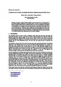
Fig. 2: System architecture of the DDF-SAM system, showing the example robots from Fig. 1 two robots performing decentralized mapping in stages: executing local SLAM in parallel and compressing locally observed maps for distribution to neighboring robots, which cache these condensed maps and finally assembling and solving a neighborhood graph
maximize generality of the approach. III. DDF-SAM In previous work [1], we introduced DDF-SAM as an approach to solving decentralized online mapping problems across multiple robots, which consists of three main modules: 1) Local Mapping Module: optimizes for the full trajectory and landmark map, then compresses a local map for broadcast to neighboring robots. 2) Communications Module: updates a cache of condensed maps from many robots. 3) Neighborhood Mapping Module: jointly estimates over landmarks in the robot’s neighborhood graph and relative coordinate frames to yield a neighborhood map. A. The Local Mapping Module The local mapping module is largely identical to the mapping performed in any single-robot feature-based SAM system, but after completion it additionally creates a condensed map. The local mapping problem in the reference frame of robot r is to create a map Θr = (X r , Lr ) r consisting of a set of landmarks Lr = {lm } and robot poses X r = {xrn }. Measurements Z = {zi } consist of odometry between poses and observations to landmarks, e.g., bearing and range. We minimize the loss function for the system (1), which is a Mahalanobis distance between predicted observation h(Θr ) and the measurement Z, assuming zeromean Gaussian noise, parameterized by the measurement covariance matrix Σ: 1 2 (1) L(Θr ) = kh(Θr ) − ZkΣ 2 Nonlinear optimization of (1) corresponds to inference in this system, with direct solvers (such as LevenbergMarquardt) iteratively improving the current estimate Θrk at iteration k with an update δk computed by linearizing (1) around Θrk , as in (2). In the linearized system, H(Θrk ) is the Jacobian of the prediction function h(Θr ) around the current estimate. Note that at the linear optimization stage, we are
+
+
G
(a) Section of neighborhood graph G
B
+
+ +
+
+ +
A
+
+
B. The Communication Module The communication module performs three key roles: 1) transferring condensed maps to other robots, 2) caching the latest condensed map from each known neighboring robot, and 3) constructing the neighborhood graph from the cached condensed maps. This approach allows information from a given robot to propagate through the communication network, even if the robot fails or falls out of communication range. To minimize the communication constraints, each robot broadcasts a listing including timestamp and source robot of its current cache state as a request for updated condensed maps. Any responding robot returns a set of condensed maps with newer timestamps, thereby propagating the condensed maps throughout the network. In order to keep neighborhood inference tractable, we bound the size of robot neighborhoods to the nearest K robots within communication range. This bound yields a significant capability of the overall distributed inference system: when robots are not observing new landmarks, the size of neighborhood graphs remains bounded by a factor of K. Adjusting K corresponds to increasing the effective sensor horizon of a given robot at the expense of computation. We construct the neighborhood graph differently than in the local nonlinear system, as the linearized factors on the condensed maps constrain these maps to the original local frame of reference. As none of the robots know the neighborhood reference frame or the relative reference frames of neighboring robots, we use constrained factor graphs as a way to simultaneously update landmarks in their local frame of reference and in a consistent neighborhood landmark map.
A
+
not solving for the new estimate itself, but rather an update to the current estimate - this distinction will prove significant when merging separate maps in Section III-B. 1 2 δk∗ = argminδ kh(Θrk ) + H(Θrk )δk − ZkΣ (2) 2 1 2 = argminδ kAδk − bkΣ (3) 2 As is standard practice, we exploit system sparsity with sparse factorization techniques. We represent the system as a factor graph Gr (Θr , Z) = {fi (Θr ; zi )}, where each factor 2 fi (Θr ; zi ) = 12 khi (Θr ) − zi kΣ relates only the variables in zi measurement, such as an odometry factor fi (xrj , xrj+1 ; zi ) or an observation factor fi (xrj , lkr ; zi ). Solving the linear system (A, b) for δk can be performed using sparse QR or Cholesky factorization [16]. After computing Θr∗ , the optimized solution to the local SLAM problem, we build a condensed map M r by marginalizing out robot poses to yield a map consisting only of landmarks Lr . This condensed map is bounded in size only by landmarks, which grows only as the robot explores new areas. To do this, we linearize the system around Θr∗ and marginalize the out the poses with partial elimination, yielding a Gaussian joint density on the landmarks. The ˜ ˜b), combined with the locally partially eliminated system (A, optimized values for landmarks, form the condensed map ˜ ˜b, Lr ). message M r = (A,
+ (b) Full graph
Fig. 3: Assembling the neighborhood graph with frame of reference constraints to bridge the neighborhood local frame of reference. Fig. 3a shows the addition of two transform constraints mapping landmarks in the local frame (right) to the neighborhood frame with the transform variable denoted by a square. Fig. 3b shows both robots from the example with all transform constraints and condensed maps.
Combining these maps requires the neighborhood graph to maintain the separation between the local side and the neighborhood side of the system, as in Fig. 3, in which we explicitly represent the coordinate frames and the relationships between landmarks observed by separate robots. Given a correspondence (lir , li ) between a local side landmark lir and its counterpart li in the neighborhood frame, we impose an equality constraint Φr ⊕li = lir between them. Each frame of reference variable Φr denotes the SE(2) transformation mapping landmarks in the neighborhood frame to counterparts in the local frame. The equality constraints have a sparse form similar to the probabilistic constraints. Fig. 3 illustrates the variables, factors and constraints in the neighborhood system, which simultaneously solves for local side landmarks Lr from each condensed map M r , a set of neighborhood side landmarks L in the neighborhood frame, and a frame of reference transform Φr for each M r . We insert the linear condensed maps on the local side of each frame of reference as a factor f r (Lr ) over the local landmarks, and then bridge the local and neighborhood side with hard equality constraints. C. The Neighborhood Optimization Module ¯ over the known condensed Once a neighborhood graph G maps has been assembled by the communication module, it is passed to the neighborhood optimization module of the robot to perform nonlinear constrained optimization. We implement constrained optimization as penalty functions at the nonlinear level, with a modified loss function combining the factors from the condensed map and the set of hard
equality constraints, with a parameter µ to adjust the gain on landmarks. This penalty function approach has been shown to converge for nonlinear systems [18]. 1X 1 XX fr (Lr ) + µ cj (lj , Φr , ljr ) (4) C(L, Φ) = 2 r 2 r j To calculate a linear update δk to the current estimate (Lk , Φk ), we construct a linear factor graph by stacking the linear systems from the condensed maps (they are already linearized), and linearizing the constraints. To solve the resulting system (A, b), in which some variables have hard constraints, we use a modified form of QR factorization which switches between Householder reflections when eliminating variables with probabilistic factors, and direct elimination when eliminating variables with any hard constraints. IV. M ULTI -ROBOT DATA A SSOCIATION The DDF-SAM system provides the optimization backend and message-passing structure for a fully decentralized mapping problem across multiple robots, but requires known, reliable data associations, as well as initial estimates for the relative frames of reference for the robots. As is typically the case with SAM approaches, a data association mismatch will have a significant effect on the final solution, so in the presence of data association uncertainty, correspondences should be chosen conservatively. Hence, we need a multirobot data association engine that can, given landmark maps from multiple robots yield 1) Correspondences mapping each local landmark lir to a neighborhood landmark li and 2) Initial estimates for each Φr , which are necessary for good optimization performance. In order to fulfill the initialization and data association requirements for neighborhood optimization, the multi-robot data association module uses a triangulation-based robust estimator for matching feature maps. We define a binary operation between landmark maps to calculate the landmark correspondences and frame of reference initializations. The map matching module associated with a given robot collects a growing set of correspondences and frame of reference transforms which can then be used during neighborhood graph construction and optimization. The outputs for this system are the transforms Φr , such that li = Φr ⊕ lir , to use as initializations for neighborhood optimization, and correspondence pairs (lir , li ) mapping local landmarks to neighborhood landmarks. In order to allow matching against other landmark maps, the map merging system for r maintains a set of triangulated maps from all known robots, initially consisting of the map from the local robot r, and upon each new message from a neighboring robot, updates the stored triangle map and computes associations with the local robot. Each map matching operation, executed upon receiving a set of landmarks La message from another robot ra , is therefore a binary operation between the current neighborhood map L and the new map La . If this matching operation returns successfully, the map merging system records the transform from the neighborhood frame to the new frame as Φa , and
Fig. 4: Matching of landmark maps. Left: two sets of landmarks (white circles), their triangulation (blue, red), triangle centers (black), and matching constraints (green). Right: matched maps.
the correspondence pairs (lia , li ) between its landmarks and the neighborhood landmarks. A. Triangle Map Matching With planar landmark maps, determining the frame of reference constraints is equivalent to finding a transformation Φa choose a between the map of the first robot and the map of the second robot, so that the number of matching landmarks is maximized. Let ra be a robot with landmark map La and L the landmarks in the neighborhood frame. In general, a unique transformation can be computed from two point correspondences. A direct application of RANSAC [13] would randomly sample (without replacement) two points from the neighborhood landmarks L and the incoming landmarks La as putatives, compute the corresponding transformation and verify it by counting the number of matched landmarks. This approach is intractable even for moderately sized landmark maps as there are exponentially many transformations to verify. To avoid the combinatorial complexity while maintaining resilience to outlier associations, associated with the naive application of RANSAC, we compute geometric features from the sets of landmarks which efficient filtering of putative correspondences enable correspondences. Similar to the approach presented by Ogawa [19] for constellation matching, our approach first computes a Delaunay triangulation of the landmark positions in L and La , and then applies RANSAC on a set of putatives generated from the centroids of similar triangles. Given a set of points in the plane, a Delaunay triangulation determines a triangulation T such that no point in the set is inside the circumcircle of any triangle in T . By computing a geometric feature on the landmarks, we can improve the inlier ratio in RANSAC to find matchings in fewer samples. We choose to use a Delaunay triangulation as a geometric feature because it is unique, invariant to reference frame, and biases the set of putatives towards conservative data
associations. In non-structured environments, such that any set of landmarks is in general position, i.e., no more than three points lie on a circle, the triangulation will be unique, even under local perturbations. Because the edges are dependent on distances, the triangulation is also invariant to the reference frame, enabling a the use of a triangle similarity metric for filtering putative associations. Another benefit of the Delaunay triangulation addresses the conservative choice of correspondences, because triangles on the frontier are more likely to be elongated and change upon new landmark, but triangles on the interior of a the map with more confident estimates will be more stable to the introduction of new landmarks. As a staple algorithm in the graphics community, the Delaunay triangulation is well studied, and can be computed in batch in O(n log n), and an existing triangulation can be efficiently updated. We obtain sets of triangles T1 and T2 for L and La respectively. Instead of matching L and La directly, our approach matches the sparser sets T1 and T2 . An illustration of this process can be seen in Fig. 4. A set of features {fij } is computed for each triangle tj to guide the search for corresponding triangles. Since we want to recover an Euclidean transformation between both maps, these features need to be invariant to Euclidean motion. For this reason, we chose the sum of triangle edges and the area of the triangles as features. For each triangle tj with edge lengths aj , bj , cj we compute: f1j = aj + bj + cj q 1 f2j = s(s − aj )(s − bj )(s − cj ), s = f1j 2 The set of correspondences C between T1 and T2 can now be defined as C(T1 , T2 ) = {(t1 , t2 ) | t1 ∈ T1 , t2 ∈ T2 , s(t1 , t2 ) < τ } (5) where τ is a threshold on the (dis)similarity of two triangles that is given by Y S(t1 , t2 ) = exp((fi1 − fi2 )2 ) (6) i
The set of correspondences C will in general contain outliers since the geometric features described above allow for some ambiguities. For this reason, we apply RANSAC on C to eliminate outliers. RANSAC is an iterative algorithm that estimates parameters of a model from a set of correspondences which contains outliers. In our system, the model corresponds to the transformation Φa between map L and La which can be described by a planar translation and rotation. Since the ordering of the triangle vertices is assumed to be unknown, we use only the center points of the triangles to compute the transformation and hence need to sample at least two point correspondences. Following the standard RANSAC algorithm, we determine Φa by repeatedly sampling two correspondences from C and returning the model that maximizes the number of matched landmarks. We use a relatively simple implementation of RANSAC in this paper to demonstrate the efficacy of our geometric
Fig. 5: A closer view of a two-robot map matching from run 1 with measurement factors shown as translucent dark lines, trajectories as blue and green paths, and optimized neighborhood landmarks as black circles.
feature approach to improving the inlier ratio. Combining these features with a more sophisticated sampling algorithm, such as PROSAC [20], or exploiting domain knowledge on the groupings of landmarks, such as GroupSAC [14], could further improve the execution time, but are beyond the scope of this paper. V. E XPERIMENTS To demonstrate and evaluate the approach, we conducted experiments in a simulated environment to demonstrate large scale operation, and with a real-world set of robots to show sufficient robustness for practical applications. For this implementation, the graphical inference and optimization engine used is the GTSAM library, with local optimization performed with an improved version of the iSAM [21], an incremental SAM solver to enable real-time performance for local SAM. The neighborhood optimization approach uses batch Levenberg-Marquardt optimization. We perform 2D triangulation with the Triangle library [22]. A. Real-world Robots To evaluate our data association and inference approach under realistic conditions, we performed experiments using a heterogeneous team of three real robots (see Fig. 6). The team consisted of an ActiveMedia Pioneer2, Pioneer2 AT and a PowerBot, each equipped with a SICK LMS 291 laser range finder. The experiment was conducted in the parking lot of the computer science campus in Freiburg. The robots were manually steered through the environment. Since the environment does not contain a sufficient amount of detectable features, a number of artificial landmarks (poles) have been placed there additionally. We used poles with a diameter of 15 cm and a height of about 100 cm (see Fig.6, top). Bearing-Range feature measurements came from a pole detector. We conducted two runs where the robots were moved in the environment for about 20 min, with trajectory
(a) Run 1
Fig. 7: Large-scale simulated scenario with 20 robot trajectories (denoted by paths of violet triangles), line-of-sight blocking obstacles, and observable landmarks (denoted with green circles). Robot trajectories are random walks that reflect off of obstacles and boundaries.
lengths ranging from 17, 000 poses to 20, 000 poses. The trajectories of the robots during the first run can be seen in Fig.6. The local map data association uses a simple nearest neighbor approach with fixed gates to determine whether to associate a new measurement with a specific known landmark or create a new landmark.
(b) Run 2
Fig. 8: Final neighborhood maps from Run 1 and Run 2 of the Freiburg dataset, where the trajectories for robots A, B, and C are red, green and blue, respectively, with black circles representing the neighborhood landmarks.
B. Synthetic Scenario We created a simulation capable of running a large number of robots at a time in randomly generated environment, including both line of sight measurements constraints and dynamic network topology. This experiment exercises the scalability of the system given bounded neighborhood sizes and dynamic network topology, as well as a means to evaluate data associations with ground truth. The simulated scenario consists of a square bounded region 100 m by 100 m, with 50 robots starting from randomly generated positions. The obstacles in the environment consist of triangles and rectangles, which block both lines of sight for measurement and robot travel. We add landmarks for mapping to the corners of all of the obstacles and the region boundary corners, as well as inserting landmarks in free areas with a minimum separation between the landmarks. The total number of landmarks is 629. Each robot can sense landmarks within a 10 m meter range and a 180◦ field of view, and as a simplifying assumption for the large scale scenario, the we use known data associations for local mapping system. This data association assumption allows us to focus on multirobot data association, which is the focus of the paper, rather than the single-robot data association. The robots drive on random walk trajectories, with a bias towards staying in a 4 m radius of their starting point, which simulates a realworld scenario in which each robot is not intended to cover the entire operating environment.
The network model used for modeling communications allows each robot to transfer condensed maps with a neighborhood the K nearest robots within 20 m. We use this scenario to measure the effect of a dynamic communications topology on communication bandwidth and neighborhood optimization timing. We vary the neighborhood size K throughout the course of the experiments. VI. R ESULTS We ran all experiments and simulations on a single machine with a Core i7 processor and 8GB of RAM under Linux, using ROS as a message-passing middleware to simulate communication between separate robots. A. Freiburg Dataset We ran the system for both Freiburg datasets to collect timing information and render the final map in each case. Fig. 8 shows the final merged map for both runs of the dataset with robot trajectories in a consistent frame and the locations of neighborhood landmarks. Fig. 5 provides close-up of a two of robots from run 1 with measurements shown, which clearly shows the observability of the landmarks. To characterize the map compression, we measured the time taken to create each condensed map, as well as the size of the ROS messages used to pass the condensed maps
Fig. 6: Robots used in the experiments and one of the landmarks (left), parking lot with landmarks (center), and an aerial view of the parking lot. Neighborhood Size K=2 K=3 K=4 K=5 K=6
zero errors 94.93% 94.32% 92.49% 91.68% 94.52%
one error 4.46% 4.67% 5.88% 6.69% 4.87%
two errors 0.61% 1.01% 1.62% 1.62% 0.61%
Map summarization time for Freiburg Dataset Run 1 900
TABLE I: Data Association Inconsistency Errors Over Time
B. Simulated Scenario In the large scale simulation, we measured the optimization time at each time interval for a specific robot and plotted in Fig. 10a the time at each simulation timestep in which the neighborhood graph was optimized with a different dataset for each value of K from 2 to 6. In this figure, we can see that the optimization time rises as the robots cover more area, but after the robots stop discovering new landmarks, the optimization time levels out and with striations in the plot for increasing neighborhood size. This supports the claim that the computational difficulty becomes bounded by K. We also measured the communication bandwidth used in different neighborhood sizes, and plotted the size of the incoming responses to a single robot in Fig. 10b. As with optimization times, the communication bandwidth also stabilizes after robots in the scenario stop discovering new landmarks. To evaluate the data associations from our algorithm, we collected statistics for the data association solution at each timestep. We measure our data association performance by counting false positive associations, when two local landmarks are are incorrectly assigned to the same neighborhood landmark. The resulting number of data association inconsistencies during the simulated experiment was quite low, with a maximum of 2 inconsistent associations across all 50 robots at any given time. Table I. shows breaks out the error rates over time for each of the neighborhood sizes, in which each percent score is the total number of errors during the course of the experiment over all robots over the total number of data association operations. An ideal score is 100% zero
700 600 500 400 300 200 100 0
0
2000
4000
6000
8000 10000 Timestep
12000
14000
16000
18000
16000
18000
(a) Time to create condensed map Condensed Map Sizes for Freiburg Dataset Run 1 60
50 Condensed Map Message Size (kb)
between robots. The results in Fig. 9 show that while the map compression time increases, which is to be expected as more poses are eliminated from the system, the size of the messages only increases when new landmarks are observed, resulting in flat sections in the growth of the messages.
Map Summarization Time (ms)
800
40
30
20
10
0
0
2000
4000
6000
8000 10000 Timestep
12000
14000
(b) Sizes of compressed map messages
Fig. 9: Timing (top) and message size for map compression operation for Freiburg dataset run 1, separated by individual robot.
Neighborhood Optimization Time vs. Neighborhood Size
and communication between robots is becomes bounded by the neighborhood size K as the robots complete exploration.
400 K=2 350
K=3
R EFERENCES
K=4 K=5
Optimization time (ms)
300
K=6 250 200 150 100 50 0
0
100
200
300
400 500 600 Simulation Timestep
700
800
900
1000
(a) Average neighborhood optimization times. Communication Bandwidth vs. Neighborhood Size 600 K=2
Incoming message response size (kb)
K=3 K=4
500
K=5 K=6 400
300
200
100
0
0
100
200
300
400 500 600 Simulation Timestep
700
800
900
1000
(b) Total size (measured as the size of serialized ROS messages) of incoming condensed map messages to each robot.
Fig. 10: Map fusion and communication bandwidth for the simulated scenario. In both cases, values are averaged across all 50 robots and separated by neighborhood size K.
errors. There appears to be a trend in the values K = 2 to 5 of increasing correspondence error rates with larger neighborhood sizes, but the size of the inconsistencies is too small in absolute terms to provide definitive confirmation of a trend. VII. S UMMARY In this paper, we presented a novel multi-robot data association method for robust decentralized mapping and validated its use with both real-world and large scale simulated experiments. This data association method resolves the data association and frame of reference initialization shortcomings of the DDF-SAM distributed inference algorithm to enable the system to be used in real-world systems at real time. The triangulation-based data association algorithm provides robust matching between maps with reliable estimates for robot reference frames. Through our large scale simulation, we empirically show that both the computation
[1] A. Cunningham, M. Paluri, and F. Dellaert, “DDF-SAM: Fully distributed slam using constrained factor graphs,” in IEEE/RSJ Intl. Conf. on Intelligent Robots and Systems (IROS), 2010. [2] H. Durrant-Whyte and M. Stevens, “Data fusion in decentralized sensing networks,” in 4th Intl. Conf. on Information Fusion, 2001. [3] T. Bailey, M. Bryson, H. Mu, J. Vial, L. McCalman, and H. DurrantWhyte, “Decentralised cooperative localisation for heterogeneous teams of mobile robots,” in IEEE Intl. Conf. on Robotics and Automation (ICRA), 2011. [4] A. Bahr, M. Walter, and J. Leonard, “Consistent cooperative localization,” in IEEE Intl. Conf. on Robotics and Automation (ICRA), pp. 3415–3422, May 2009. [5] L. Andersson and J. Nygards, “C-sam : Multi-robot slam using square root information smoothing,” in IEEE Intl. Conf. on Robotics and Automation (ICRA), 2008. [6] B. Kim, M. Kaess, L. Fletcher, J. Leonard, A. Bachrach, N. Roy, and S. Teller, “Multiple relative pose graphs for robust cooperative mapping,” in IEEE Intl. Conf. on Robotics and Automation (ICRA), (Anchorage, Alaska), pp. 3185–3192, May 2010. [7] A. Howard, “Multi-robot simultaneous localization and mapping using particle filters,” Intl. J. of Robotics Research, vol. 25, no. 12, pp. 1243– 1256, 2006. [8] L. Carlone, M. Ng, J. Du, B. Bona, and M. Indri in IEEE Intl. Conf. on Robotics and Automation (ICRA), pp. 243 –249, May 2010. [9] A. Howard, “Multi-robot mapping using manifold representations,” in IEEE International Conference on Robotics and Automation, (New Orleans, Louisiana), pp. 4198–4203, Apr 2004. [10] K. Ni and F. Dellaert, “Multi-level submap based slam using nested dissection,” in IEEE/RSJ Intl. Conf. on Intelligent Robots and Systems (IROS), 2010. [11] T. Bailey and H. Durrant-Whyte, “Simultaneous localisation and mapping (SLAM): Part II state of the art,” Robotics & Automation Magazine, Sep 2006. [12] J. Neira and J. Tardos, “Data association in stochastic mapping using the joint compatibility test,” IEEE Trans. Robot. Automat., vol. 17, pp. 890–897, Dec. 2001. [13] M. Fischler and R. Bolles, “Random sample consensus: a paradigm for model fitting with application to image analysis and automated cartography,” Commun. ACM, vol. 24, pp. 381–395, 1981. [14] K. Ni, H. Jin, and F. Dellaert, “Groupsac: Efficient consensus in the presence of groupings,” in Intl. Conf. on Computer Vision (ICCV), (Kyoto; Japan), October 2009. [15] R. Aragues, E. Montijano, and C. Sagues, “Consistent data association in multi-robot systems with limited communications,” in Robotics: Science and Systems (RSS), (Zaragoza, Spain), June 2010. [16] F. Dellaert and M. Kaess, “Square Root SAM: Simultaneous localization and mapping via square root information smoothing,” Intl. J. of Robotics Research, vol. 25, pp. 1181–1203, Dec 2006. [17] G. Grisetti, C. Stachniss, and W. Burgard, “Non-linear constraint network optimization for efficient map learning,” Trans. on Intelligent Transportation systems, 2009. [18] P. Lindstrom and P. Wedino, “Gauss-newton based algorithms for constrained nonlinear least squares problems,” Tech. Rep. UMINF901.87, Institute of Information Processing, University of Umea, Sweden, 1988. [19] H. Ogawa, “Labeled point pattern matching by delaunay triangulation and maximal cliques,” Pattern Recognition, vol. 19, pp. 35–40, January 1986. [20] O. Chum and J. Matas, “Matching with PROSAC - progressive sample consensus,” in IEEE Conf. on Computer Vision and Pattern Recognition (CVPR), 2005. [21] M. Kaess, A. Ranganathan, and F. Dellaert, “iSAM: Incremental smoothing and mapping,” IEEE Trans. Robotics, vol. 24, pp. 1365– 1378, Dec 2008. [22] J. R. Shewchuk, “Triangle: Engineering a 2D Quality Mesh Generator and Delaunay Triangulator,” in Applied Computational Geometry: Towards Geometric Engineering (M. C. Lin and D. Manocha, eds.), vol. 1148 of Lecture Notes in Computer Science, pp. 203–222, Springer-Verlag, May 1996.