In the case of predic- tive brake assist (PBA), for âEXAMâ ple, the ..... 9, pp. 51-55. [11] Schwerin, W.; Jenter, M.: AUTOSAr-Evaluierung bei BMW. realTimes ETAS ...
COVEr STOry
Autosar
Function and Software Development for ECUs Mechatronic systems comprise a substantial segment of the feature and function set of modern automobiles. The cost efficient implementation of intelligent functions, both within and beyond the domains of powertrain, chassis, and body, is accomplished with the aid of electrics, electronics, and software. Autosar supports the reuse of software indigenous to these systems. Besides providing an overview of the system levels that determine the behavior of complex vehicle functions, this article by Etas also discusses the deployment of methods and tools in the interworking development of ECU functions and software.
10
ATZelektronik 06I2008 Volume 3
1 Introduction As a function of the rising demands on modern automobiles’ convenience, safety, and environmental compatibility, the number and complexity of electronically implemented vehicle functions, are steadily increasing. Today’s midsize cars feature some 40 electronic control units (EUs), all of which are interconnected by onboard data buses. Modern engine control modules process up to 250 MIPS (million instructions per second); these may contain upwards of 20,000 function parameters required for adjusting engine management functions. The same magnitude applies to the volume of code onboard the ECU, the logical core of all control functions. This, in turn, increases the software’s share in the overall vehicle price. This makes automotive software a product of strategic significance for both automakers and system vendors [1].
2 Vehicle Systems Automobiles and their internal systems are characterized by high reliability, low manufacturing costs, and long product lifecycles. At the same time, the most diverse vehicle types and model variants, ranging from luxury class vehicles to mini-compacts, are concurrently developed and distributed. The main objective of platform strategies devised by manufacturers and system vendors is the highest possible degree of reusability of systems or system components in a variety of vehicle models. The way in which electronic controls are developed depends on functional demands on the one hand, and on commercial and technical specifications – including the availability of installation space – on the other. Additional functions can be implemented through system networking. In the case of predictive brake assist (PBA), for “EXAM” ple, the distance from the preceding vehicle is measured by the radar sensor of an adaptive cruise control. This data is evaluated by the braking system, enabling it to prepare for emergency braking in case of danger. There is also a growing trend toward the deployment of central system controls in previously independent domains. In a hybrid vehicle, for “EXAM” ple, IC engine and electric motor, brake
and generator, transmission and energy consumption are simultaneously interlinked and jointly controlled [2].
3 ECU Software – Major Trends and Challenges In its function as a central system component, ECU software must be of high quality, and – concurrent with a system’s lifecycle – it must be upgradeable over a long period of time. The software must be adaptable to various system variants and vehicle types. To this end, software functions are parameterized in such a manner that the greatest possible number of software applications can be facilitated by virtue of the adaptation (or calibration) of characteristic values. To master the sheer number, scope, and variants of these functions, ECU software is divided into logical components that lend themselves to being reused due to quality and efficiency considerations. Frequently, the development of new functions and their attendant ECU software is an effort shared by workgroups coming from different domains and belonging to different companies. The increasing workload distribution and globalization of development processes calls for standardized software architectures and methods, as well as powerful tools and processes.
The Authors Dr. Matthias Klauda is CEO of Etas GmbH in Stuttgart (Germany).
Dr. Ulrich Lauff is Technical Editor-inChief for Software Engineering, Measuring, Calibration, and ECU Diagnostics in the Marketing Department of Etas GmbH in Stuttgart (Germany).
4 Autosar – a New Standard for Software In 2003, industry efforts aimed at standardizing the software for electronic control systems under the motto “cooperate on standards, compete on innovation” led to the founding of the Autosar development partnership (www.autosar.org). Its more than 100 members are jointly working toward defining a uniform software architecture for electronic control units, and toward standardizing a consistent development methodology. Within the three layer architecture, the application software – containing the open-loop/closed-loop and diagnostic algorithms – is encapsulated in separate components that communicate through Autosar conformant interfaces. All communications between software comnents ATZelektronik 06I2008 Volume 3
11
C ove r sto r y
Autosar
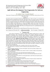
Figure 1: Analysis, specification, implementation, and integration of functions and software in vehicle electronics
– whether within the ECU or ECU network, or with sensors and actuators – is handled on the central layer, the socalled runtime environment (RTE). The RTE serves as the interface to the basic software, which provides communication and diagnostic protocols, drivers, the microcontroller’s operating system (OS), as well as system services in the form of software modules with standardized interfaces. Autosar uses this basic architecture to define methods for the ECU independent design of software components at a logical abstraction level, the so-called virtual function bus (VFB), as well as the assignment of components to the individual ECUs of an overall system. The most recent Autosar releases provide the basic specifications for the production specific deployment of ECUs running Autosar conformant software. The releases define the interfaces of both basic software modules and RTE, the exchange formats and templates for the design and distribution of software components, plus an initial selection of standardized application software interfaces.
5 Function Development and ECU Software Implementation The principal subject of the Autosar standard, namely, the description and 12
ATZelektronik 06I2008 Volume 3
implementation of ECU software, is based on the definition of functions to be implemented in the software. Function development normally occurs in three steps: Following Step One – an analysis of the requirements for an application, such as an engine control unit, Step Two specifies the individual open-loop/closed-loop control and diagnostic functions, such as injection or ignition. Step Three consists of mapping individual function algorithms, like the load dependent calculation of the firing angle, Figure 1. The software integration process converts and encapsulates an application’s algorithms in software components. The ECU software – for instance, that of the engine control unit – is then assembled from software components and basic software and subsequently integrated in the ECU, Figure 1. As part of the ongoing update of the Autosar precursor project East-EEA, the East architecture description language was further developed within the scope of the publicly funded Atesst initiative (Advancing Traffic Efficiency and Safety through Software Technology, www. atesst.org), itself an initiative of the Sixth Framework Programme (FP6) within the EU’s “IST” (Information Society Technologies). Based on applicable engineering specifications, the domain specific “East-ADL2” language
describes and analyzes vehicle electronics and software functions subsequent Autosar conformant implementation. The implementation of system requirements in terms of features, reciprocal effects, and variants can thus be tracked across the various levels [3]. The development of functions and ECU software avails itself of tools offered by tool vendors such as Etas. While the discussion below makes reference to applications of Etas tools, no claims of exclusivity or completeness of descriptions given are expressed or implied. The “ASCET” function and software development environment is capable of displaying functions either graphically, in the form of block diagrams or state machines, or in text form with the aid of the control specific description language termed ESDL (Embedded System Description Language) [4]. The behavior of the algorithms implementing the specified functions can be simulated on the PC and validated in the real-world environment with the aid of a real-time experimentation system that augments or replaces the target ECU (Rapid Prototyping; [5, 6, 7, 8]; Figure 2, Step 1 and Step 2). By exploiting the computing power of a PC or experimentation system, and with the primary focus on the “physical” closed-/ open-loop control behavior, the function algorithms are implemented in floating point arithmetic.
Once the function algorithms meet the requirements for open-loop/closedloop controls, they are executed in fixed point notation in accordance with the ECU software specifications. For individual variables, this includes the definition of data types with a suitable resolution, adaptation of the calculation routines, and the generation of conversion formulas for the physical representation. A prototyping experiment provides an easy means of verifying the fixed point version of a given software function through comparison with the physical model. The function algorithms are then transferred to software components, and the data structures and communication mechanisms for the component interfaces are specified. The final step consists of the automatic generation of ECU code, Figure 2, Step 3. “ASCET” developed Autosar software is already deployed in a variety of production projects [10, 11]. Prototyping environments such as “INTECRIO” already provide options for validating Autosar conformant applications either in a virtual environment or in the real-world system, Figure 2, Step 1 and Step 2. Irrespective of the modeling environment, the “INTECRIO” integration platform can be used to assemble interconnected Autosar conformant software components to form an application by means of the virtual
function bus on the PC [12], which is then tested either directly on the PC [13] or under real-world conditions [14], Figure 3 and Figure 4.
6 Timing Behavior Logical aspects notwithstanding, system integration requires that the desired timing behavior of an open-loop/closed-loop control be guaranteed. Timing behavior is largely determined by latencies occurring as a function of signal transfer and computing tasks, whereby sensors and actuators, as well as the communication mechanisms of vehicle buses and ECUs, may delay the transfer. In distributed systems in particular, bus communications markedly influence the timing behavior of electronic controls. To avoid transmission time fluctuations during signal transfer, time controlled bus systems such as Flexray (www.flexray.com) transfer signals in predetermined time slices. Although the most recent Autosar specifications still ignore the time related characteristics of software and system architectures, efforts within the scope of Phase II of the Autosar project and the EU sponsored Itea2 (Information Technology for European Advancement) project designated Timmo (Timing Mod-
el, www.timmo.org) are aimed at discussing concepts and methods to include a structured means of including the consideration of timing behavior in the design of new vehicle systems. On the tool side, harmonized solutions facilitating the analysis of system timing behavior were presented within the framework of the Interest (Integrating European Embedded System Tools) project. Thanks to a coupling of “ASCET” with AbsInt’s aiT Worst Case Execution Time (WCET) analysis tools, the maximum execution times of individual operations of software components can be determined by means of program code analysis. Similarly, the “SymTA/S” tool by Symtavision permits the determination of maximum signal runtimes between sensor input and output on the basis of analyzed WCET data as well as OS and vehicle bus schedules, facilitating the identification of time delaying factors within the system [15].
7 ECU Software Integration The open-loop/closed-loop control and diagnostic functions are tested in a simulated environment in the laboratory (system test, see Figure 2, Step 4). To this end, ECUs are connected to actuators or dum-
Figure 2: Development and integration of functions, software and ECUs in virtual and physical environments ATZelektronik 06I2008 Volume 3
13
C ove r sto r y
Autosar
8 ECU Software Application
Figure 3: Integration of software components and validation of functions on the PC using “INTECRIO”; verification of the execution of function algorithms with “RTA-TRACE”; pre-calibration of function parameters on the PC with “INCA”
my loads on the hardware-in-the-loop (HiL) test bench. These are then networked and stimulated with the aid of recorded measurement data or a plant model simulating, besides the remainder of the system, also driver behavior, vehicle, and environment. In this test, the ECUs are electrically interconnected with the simulation model through realtime capable interface modules. The presence of appropriate hardware facilitates the simulation of electrical faults, such as short-circuits and wiring discontinuity [16, 17, 18]. The attendant testing of the increasingly complex open-loop/ closed-loop control and diagnostic functions for ECUs is done with the aid of more and more detailed plant simulations. With its annual increase in computing power, PC technology provides a suitable platform for computation intensive simulations. For ““EXAM” ” ple, today’s Core 2 Quad processors permit the execution of complex driving dynamics models in real time on the PC – a feat that would have been impossible only a short while ago, despite the availability of dedicated hardware for real-time simulation [19]. Subsequent to the system integration, the entire mechatronic sys14
ATZelektronik 06I2008 Volume 3
tem is subjected to test bench or in-vehicle trials with the deployment of appropriate test instrumentation [20], Figure 2, Step 5.
ECU software is parameterized in such a manner that the behavior of openloop/closed-loop control and diagnostic functions can be simply adapted to a variety of system variants or vehicle models by calibrating, or modifying, the characteristic values of function algorithms, without the need to change calculation routines. Using calibration tools such as “INCA” , characteristic values can be calibrated onthe-fly while at the same time acquiring signals from ECU, vehicle buses, and measuring devices. Calibration tools support the standardized data description formats as well as measurement and calibration protocols defined by the Association for Standardization and Automation of Measuring Systems (www.asam.net). Diagnostic functions and protocols can be declared in a standardized form by means of the ODX (Open Diagnostic Data Exchange Format, Asam AE MCD2D). When calibration procedures require a large number of variables to be measured at the same time and/or in short intervals, development ECUs are equipped with additional, powerful interfaces [6].
Figure 4: Early in-vehicle validation of function prototypes in the vehicle using “INTECRIO” and the rapid prototyping hardware ES910; integration of the prototype in existing ECU networks through bypass and bus interfaces (CAN, ETK, Flexray)
9 Summary The results presented by Autosar to date provide an essential basis for interworking software development. The component based and standardized architecture simplifies system integration, scaling, modification, and maintenance. In the ideal case, the underlying software development process is consistent, transparent, and feedback driven. Standardized data formats and interfaces facilitate the exchange of artifacts and easy tool integration in the development process. With the availability of suitable methods and tools, function models can become the basis for the development of complex electronic vehicle functions. If models contain – besides ECU software architecture and interfaces – suitable information from other architecture levels both technological and logical, then complex system interactions, such as the timing behavior of distributed openloop/closed-loop control functions can be figured into the design from the outset. As a result, model based development tools enable engineers to develop solutions at the abstraction levels corresponding to their problem manifestation. The modular ECU software architecture supports the calibration of individual functions, which starts with a PC based simulation and ends with the system integration in the vehicle, and which is subject to ongoing refinement. Based on environment models and optimization methods, calibration procedures can be automated to a large extent.
References
[1] �McKinsey (Hrsg.): HAWK 2015 – Knowledge-based Changes in the Automotive Value Chain. Germany (2003) [2] �Bauer, R.; Raste, T.; Rieth, P. E.: Systemvernetzung von Hybridantrieben (System Networking of Hybrid Drives). ATZelektronik (2) Vol. 4, December 2007, pp. 6-11 [3] �Cuenot, P.; Frey, P.; Johansson, R.; Lönn, H.; Törngren, M.; Sjöstedt, C.J.: Engineering Support for Automotive Embedded Systems – beyond AUTOSAR. Sprnger Automotive Media (/pub.), FISITA 2008 World Automotive Congress F 200805-053 [4] �Gupta, M.; Lauff, U.; Wolff, H. J.: Professionelle Umgebung für die Entwicklung von Steuer gerätesoftware - “ASCET” V6.0 (Professional Development Environment for ECU Software – “ASCET” V6.0). Hanser automotive (2008) Vol. 10, pp. 84-87
[5] �Triess, B.; Müller, Ch.; Lauff, U.; Mößner, C.: Entwicklung und Applikation von Motor- und Getriebesteuerungen mit der ETK-Steuergeräteschnittstelle (Development and Calibration with the ETK ECU Interface). ATZ Automobiltechnische Zeitschrift (109) Vol. 1, January 2007, pp. 32-39 [6] �Kulzer, A.; Laubender, J.; Lauff, U.; Mößner, D.; Sieber, U.: Der Direktstart - Vom Modell zum Demonstrator (Direct Starting – From Model to Demonstrator). MTZ Motortechnische Zeitschrift (67) Vol. 9, September 2006, pp. 636-644 [7] �Gebhard, M.; Lauff, U.; Schnellbacher, K.: Operation am offenen Herzen – Entwicklung und Test von Steuergerätefunktionen mit der Bypassmethode (Teil 1) (Open Heart Surgery – Development and Testing of ECU Functions with the Bypass Method, Part 1). Elektronik Automotive (2008) Vol. 6, pp. 34-39 [8] �Dubitzky, W.; Eismann, W.; Schinagel, J.: Entwicklung und Test von Steuergerätefunktionen mit der Bypassmethode (Teil 2) (Development and Testing of ECU Functions with the Bypass Method, Part 2). To be published in Elektronik Automotive (2008) Vol 8 [9] �Freund, U.; Lauff, U.; Wolff, H.J.; Ziegenbein, D.: Modellbasierte Entwicklung von Autosar-Anwendungssoftware (Model Based Development of Autosar Application Software). ATZelektronik (2), Vol. 4, December 2007, pp. 12-16 [10] �Freund, U.; Lauff, U.; Siwy, R.; Wolff, H.J.; Ziegenbein, D.: Sauberer Schnitt – Modellbasierte Entwicklung von Anwendungssoftware mit AUTOSAR-konformen Schnittstellen (Clean Cut – Model Based Development of Application Software with AUTOSAR Conformant Interfaces). Elektronik Automotive (2007) Vol. 9, pp. 51-55 [11] �Schwerin, W.; Jenter, M.: AUTOSAR-Evaluierung bei BMW. RealTimes ETAS Group-Magazin (2007) Vol. 2, pp. 12-13 (www.etas.com/realtimes) [12] �Lauff, U.: Offen für Autosar. Automobil Elektronik (2008) Vol. 1, pp. 26-28 [13] �Critchely, O.; Tracey, N.: RTA-OSEK erweitert Support für virtuelle Entwicklung um Echtzeit. RealTimes ETAS Group-Magazin (2008) Vol. 1, pp. 38-39 (www.etas.com/realtimes) [14] �Stix, P.; Wagner, J.: Function Development for FlexRay ECUs. Hanser automotive (2006), Special Edition FlexRay, pp. 38-42 [15] �Frey, P.; Freund, U.: Integrating Timing Aspects in Model- and Component-based Embedded Control System Development for Automotive Applications. In: Giese, H.; Huhn, M.; Nickel, U.; Schätz, B. (pub.) – Conference Minutes Dagstuhl-Workshop MBEES, Informatik-Bericht 2008-02, TU Braunschweig [16] �Wolters, U.; Elbs, M.: New Methods and Practices in Automated Testing of Automotive ECUs. In: Grote, C.; Elster, R. (pub.), Design&Elektronik, Begleittexte zum Entwicklerforum Kfz-Elektronik und FlexRay Solution Day, Poing (2007), pp. 165-174 [17] �Wittler, G.; Crepin, J.: Real-time and Performance Aspects of Hardware-in-the-Loop (HiL) Testing Systems. ATZ online (www.atzonline.de), Special: Simulation [18] �Bayerl, A.; Wandling, F.; Wolters, U.: FlexRay Residual Bus Simulation on HiL Testing Systems. Hanser automotive (2007), Special Edition FlexRay, pp. 6-9 [19] �Wittler, G.: PC-Standardtechnologien im praktischen Einsatz für HiL-Testsysteme (Practical
Application of Standard PC Technologies in HiL Testing Systems). In: VDI-Berichte 2009 (Hrsg.), AUTOREG, Düsseldorf (2008), pp. 647-655 [20] Lauff, U.; Lochau, S.: Kleine Ethernet-Module messen Signale in Sensornähe (Compact Ethernet Modules Measure Signals Close to Sensors). ATZelektronik (1) Vol. 4, November 2006, pp. 50-55
ATZelektronik 06I2008 Volume 3
15