must be adaptable to the market demands. There are two tools currently known based on IEC 61499, i.e. FBDK from Rockwell. Automation [13] and CORFU [14].
Panjaitan, S.; Frey, G.: Functional Design for IEC 61499 Distributed Control Systems using UML Activity Diagrams. Proceedings of the 2005 International Conference on Instrumentation, Communications and Information Technology ICICI 2005, Bandung, Indonesia, pp.64-70, Aug. 2005.
Functional Design for IEC 61499 Distributed Control Systems using UML Activity Diagrams Seno Panjaitan and Georg Frey Juniorprofessorship Agentbased Automation (JPA2), University of Kaiserslautern, Kaiserslautern, Germany E-mail: (panjaitan,frey)@eit-uni-kl.de Abstract – Distributed Control Systems (DCSs) are presently standardized by IEC 61499 that proposes the use of Function Blocks (FBs) to control automation process. Reusability and flexibility of the control software are achieved as one of the main factors that initiated the appearance of this standard. Meanwhile, it is important to make a controller system easy to design since market demands change rapidly. Consequently, a control strategy should be re-designable as fast as possible. This paper describes a method to design a system with the common functionality allocation approach based on the fundamental functionality of the system processes. By building generic FBs based on this approach it is expected that the design of a controller for a system can be easier, the software component can be reused, and configuration and reconfiguration of the system can be more flexible. For modeling the behavior of the FBs Activity Diagrams of UML are investigated since they are based on Petri net semantics and therefore allow the transparent description of concurrent behavior. Finally, the implementation of functional design of the system is described to illustrate the advantages of using this approach. Keywords – IEC 61499, Distributed Control System, Design Method, UML, Reusability
I. INTRODUCTION Currently, there is a growing interest in new technologies and architectures for creating the next generation of Distributed Control Systems (DCSs) for industrial automation. The realization of reusability and flexibility is one of the important points of view that stimulated the development of the standard IEC 61499 as a framework for assembling distributed automation systems. This standard specifies how Function Blocks (FBs) can be used in distributed Industrial Process, Measurement and Control Systems (IPMCS) [1]. Meanwhile, it must be possible to adapt the control strategy to new production scenarios as fast as possible due
to the challenges of global economic competition. Consequently, designing DCS controllers should concern aspects such as easy reuse of components, easy further system development that means easy to design, high understandability, and high reconfigurability. Therefore, to take those aspects into account, a good design method of DCS controllers is needed. Furthermore, there are three major issues in designing DCSs: the programming of the control application code, the functional allocation of the control application code to the specific devices, and the mapping of the distributed control application code to the underlying communication platforms depending on the distribution [2]. Considering the second issue and inspired by a schema for the improved allocation of functionality [3], this article addresses reusable distributed software components as allocation of libraries according to IEC 61499. These software components are based on basic functionalities usually used in manufacturing. To make the FBs more generic, an information-hiding principle is applied. Concisely, this principle has a simple meaning, i.e., the user should be able to change the surrounding of the module (input parameters and operations) without changing the module itself. By using this approach, it is expected that the effort in designing and redesigning of a system can be reduced. In system development, modeling of controllers is commonly recognized as an essential step towards their verification and validation in the control system. Execution Control Chart (ECC) in IEC 61499 is a specialized state machine to model the internal behavior of basic FB instances. However, this state machine does not de-
Panjaitan, S.; Frey, G.: Functional Design for IEC 61499 Distributed Control Systems using UML Activity Diagrams. Proceedings of the 2005 International Conference on Instrumentation, Communications and Information Technology ICICI 2005, Bandung, Indonesia, pp.64-70, Aug. 2005.
scribe the complexity of activities inside the FB, since it is hidden in a state’s associated algorithm. Moreover, an ECC cannot express concurrent processes inside of the FB itself. Manifold approaches to manifest the behavior of FBs according to IEC 61499 are published: Signal/Net Systems [4], Petri Nets [5], Timed Automata [6], and UML class diagrams, state chart and sequence diagrams [7], [8]. In the presented work, UML Activity Diagrams (ADs) are investigated to describe FB behavior. ADs are based on Petri net semantics and therefore allow the transparent representation of concurrent behavior. The rest of this paper is systematized as follows: in the next section, functionality based controllers are introduced. Section III elucidates the model of FBs by using ADs that show the behavior of the functional operation. In section IV implementation results of the proposed method are depicted. Finally, in the last section, conclusions are drawn along with a presentation of the prospective features. II. FUNCTIONALITY BASED CONTROLLER In manufacturing, controllers are assigned with responsibilities of controlling and monitoring various processes. Automation processes doing the identical tasks are frequently being inhabited in miscellaneous control software. Consequently, system design takes a lot of time, cost, and energy. For that reason, the approach based on more generic functionality-oriented FBs is introduced for designing and controlling IEC 61499 compliant DCSs. It will be helpful in dynamically shifting to a new process scenario of the system. Functionality based controllers (FBCs) can be denoted as various components. Table 1 exhibits some examples of FBCs and their corresponding hardware components in automation system. To make the design more efficient, similar tasks can be controlled by the reuse of the common functionality. In Table 1, there are two kinds of “Movement 1 point” FBs, namely, with
and without transition. With transition is used if the position of the destination sensor is located on the start position, therefore in initial movement the controller ignores the sensor condition for a particular delay time. Without transition is used if the destination location is not on the same place as the initial position. For “Movement 2 points” FBs, the direct option represents an action for forward and backward with just one event input; on the other hand, with the indirect choice, the first event input performs the forward action and the second one is for backward. Functionality Movement 1 point (with transition / without transition) Movement 2 point (direct / indirect)
Component Conveyor, rotary, crane motor, etc.
Push/pull cylinder, transporter 2 point, Lifter 2 point, Driller, Tester, etc. Action 1 Suction (pneumatic), thickness test, etc. FIFO memory Color memory, sequence memory, etc. Table 1. Functionality controller examples. Furthermore, some distinct operation modes are also considered in designing a system process i.e., setup, automatic, and emergency stop (caused by human interruption or time reach out). These modes are of important concern since flexibility must cover some probable situations. For functionality that has just one action, for example movement 1 point and action 1, selecting mode is not needed since it just has single activity that can be executed from primary controller by releasing event to it. Otherwise if instance block has more than one actuator, for example movement 2 points, mode should be included in functionality module in order to distinguish the kind of operation status when an event occurs. Thus the interconnections among functionalities are dependant upon the desired control strategy for a plant. Each instance should approve reusability where a func-
Panjaitan, S.; Frey, G.: Functional Design for IEC 61499 Distributed Control Systems using UML Activity Diagrams. Proceedings of the 2005 International Conference on Instrumentation, Communications and Information Technology ICICI 2005, Bandung, Indonesia, pp.64-70, Aug. 2005.
tionality type can be instantiated with different names. The architecture for designing the application of FBCs is depicted in Fig. 1. It can be seen that functional controllers (F1, F2,…, Fn) inherit generic functionality (Funct. 1, Funct. 2, etc). Some instance blocks can use the same type. For example, F1 and F3 use the same generic function linked to library. To control the execution of the function control manager (CM) is used. The CM sends data to the selector for selecting which functionality will work as well as the synchronizer for evaluating the process validation. Selector and synchronizer can employ a single task as well as multitasks. For selecting the function a formula is proposed as follows: n −1
S ( j ) = ∑ F (i + 1) ⋅ 2i i =0
where : S ( j ) : Data value for process execution F ( j ) : FBC number n ; [0,1]
Control manager
Selector
Synchron.
F(1) : Funct. 1 F(2) : Funct. 2 F(3) : Funct. 1
F(n) : Funct. 2
Fig. 1 Architecture for controlling FBCs CM will pass the S(j) value to select
which functions will be executed. This value is also given to synchronizer for waiting until all tasks according to it have been done. For example, if CM supposes to execute F1 and F2 as a multitasking case, hence it must give 3 to selector. Furthermore, except in the case of an emergency stop caused by time reach out of function, CM passes the other messages to the selector too, such as operation mode, task num-
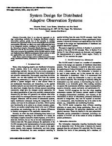
ber, and time constraint. For more information on the scheduling approach see [12]. III. MODELING WITH ACTIVITY DIAGRAM UML The Unified Modeling Language (UML) is the new industry standard for modeling software-intensive systems. Currently, it is moving from version 1.5 to version 2.0. One of the significant improvements is in the definition of activity diagrams (ADs). The ADs blend ideas from several techniques: the event diagram of James Odell, SDL state modeling techniques, and Petri nets [9]. These diagrams are particularly useful for describing activity connections and their behaviors even when they have a lot of parallel processing. Moreover, it shows the process explicitly as well in order to give a good understanding about the system conduct. By using this kind of diagram, the designer or user has the ease to understand the control scenario. Therefore, the activity diagram is regarded as a behavior model of the FBs that represents the FBCs. In this paper Borland Together Control Center 6.2 tool is used to model ADs for FBCs. During the rest of this paper a part of a didactic production system, i.e., feeder station has been considered as the controlled object. Its physical model is shown in Fig. 2. The specification of the control software is contrived by the following requirements: 1. An initial process setup mode should be undertaken before running the normal operation so that the each of the mechanical elements takes its initial position. 2. During normal operation the machine will perform the action of pushing the cylinder forward to supply a work-piece to the transporter. In case a work-piece can be supplied, the transporter moves to the right to take it, the suction process is done and the supplier is pulled to the initial position. After that the transporter moves back to its initial position and puts the work-piece on the place for availability to the following process. Then the pusher distributes a work-piece again. Finally, the transporter
Panjaitan, S.; Frey, G.: Functional Design for IEC 61499 Distributed Control Systems using UML Activity Diagrams. Proceedings of the 2005 International Conference on Instrumentation, Communications and Information Technology ICICI 2005, Bandung, Indonesia, pp.64-70, Aug. 2005.
moves again to the position where workpieces are placed and waits for confirmation of the ending operation of the next station. In case no work-piece can be supplied, the cylinder must go back to the initial position and suspend the operation until the tube has been refilled.
Fig. 2 Physical Model of Feeder Station 3. In case a fault occurs because the process cannot finish the given task within a particular time limit or an interruption request arrives from outside, the process will move to a safe emergency stop mode. 4. For direct option, the system will finish more than one task, i.e. forward and reverse, then give End signal to other modules as an indicator that the process has been finished. Besides, indirect option will give End signal after one task has been done, i.e. forward or reverse.
Fig. 3 AD of Movement 2 Points
Fig. 3 shows the AD for Movement 2 points in two directions i.e. forward and backward. Some operation modes are esteemed to cover several different processes. It can be seen that there are three receivers as event inputs and four transmitters as event outputs used to get or give event signals from or to other module objects. Join as synchronization and decision as selector of the next activity depending on guard are also employed for delineating interrelation between activities. Between two activities, i.e., forward and reverse, direct or indirect step to the next task is confirmed. Fig. 4 depicts the interconnection among AD modules to build a feeder system in normal operation. It can be seen that initial start comes from controller manager and then invokes activity in AD of feeder. This model is arranged simply in order to give a good understanding of the operated activity. In case the position of feeder is already at the end and the matter is distributed successfully the next activity, in module Transport, is performed. In contrast, if matter is not distributed successfully it will invoke the activity in the same module. Then it will be finishing the process in state by informing the status that matter must be filled in the tube. Back to the first case, when the forward activity is done then reverse in Feeder module and RUN in Pick module are fired by fork component. When those two activities are done the reverse in Transport module is executed with join transition component. Finally, when the matter has arrived RUN activity in Put module will be invoked. The reuse of functionality appears in Feeder and Transport that inherit same type of functional module, i.e. Move_2_set, and also Action_1 used by Pick and Put. In larger systems these FBCs can be re-used for applying the same functionality to help designer moving from one control scenario to another one when the hardware components are changed that imply to a re-design process. The AD description helps users and designers to easily understand the desired activity flows of the system.
Panjaitan, S.; Frey, G.: Functional Design for IEC 61499 Distributed Control Systems using UML Activity Diagrams. Proceedings of the 2005 International Conference on Instrumentation, Communications and Information Technology ICICI 2005, Bandung, Indonesia, pp.64-70, Aug. 2005.
(SIFB) [10]. Certainly, the FB actuates an action and then waits till a desired state is reached, indicated by sensor signal. When a time-out occurs before completion of the assigned task the EstopO output event is fired denoting the erratic situation and further processing is paused till the operator settles it. Besides, when the assigned task has been finished the End output event is published as a confirmation to Synchronization FB.
Fig. 4 AD of Feeder Station (normal) IV. IMPLEMENTATION OF THE CONTROLLERS In the previous section activity diagrams of FBCs have been presented. For implementing such a diagram to real system level FB based on generic functionality of manufacturing is proposed since designing and re-designing manufacturing process must be adaptable to the market demands. There are two tools currently known based on IEC 61499, i.e. FBDK from Rockwell Automation [13] and CORFU [14]. In this paper, the first one is used. As an example, the FB as an instance of functionality for controlling movement 2 points is shown in Fig. 5. The event input Start and Estop trigger a normal operation and emergency stop respectively, i.e. stalling of any continuing task. The data inputs named mode, direct, and t_constr specify the operation in the algorithm. Based on information-hiding principle we can change the mode of operation and the executed algorithm of FB from outside of the instance. The other inputs are for taking sensor signals in order to recognize the state of the process. The output events correspond to confirmation of algorithm completion. Outputs represent actuator signals, which are communicated to the hardware via Service Interface Function Block
Fig. 5 Movement 2 points FB Furthermore, the other FBCs mentioned in section II have been developed in this work. These function blocks and the other available types will be interconnected to each other to build a control system. In practice, controller interfaces using (SIFBs) from FBDK for I/O modules are used to apply that system. As controller hardware NETMASTER is used that contains a TINI microcontroller supporting high-level languages like Java and C [11]. On the one hand this provides the advantage of programming applications for them without specialized expertise of proprietary or assembly-like low-level languages. On the other hand, the microcontrollers provide these programming platforms with the help of native platforms and the applications written in high-level languages must go through the native layer and operating system layer to reach the peripherals. For this purpose, Service Interface Function Blocks (SIFBs) for the Netmaster module hare used [10]. The implementation schema using the FBDK tool and the Netmaster can be seen in Fig. 6. The source program mentioned
Panjaitan, S.; Frey, G.: Functional Design for IEC 61499 Distributed Control Systems using UML Activity Diagrams. Proceedings of the 2005 International Conference on Instrumentation, Communications and Information Technology ICICI 2005, Bandung, Indonesia, pp.64-70, Aug. 2005.
above will be deployed over Ethernet into Netmaster. Each Netmaster module has 8 digital I/O and 6 keypads that are needed for the application. Finally, programs embedded in each of the modules control all I/O Netmaster modules.
Fig. 6 The schema of implementation V. CONCLUSION AND OUTLOOK We have explicated an approach of achieving reusability and flexibility using functional design for distributed control system based on IEC 61499. The ADs are also investigated to describe the behavior of the design in terms of activity workflow. With Encapsulation of common mechanism work as a software module built by FB concept to enable “plug and play” in the realm of IPMCS, it gives a new alternative for design paradigm. Furthermore, the notation used to build this module can help users to understand and design easily. As the next step of this work a method to generate FBDK code from the respective UML activity diagrams will be developed. Furthermore, the application of Petri nets in the design is planned since AD is based on Petri net semantic. This will pave a way for formal modeling and system verification. VI. REFERENCES [1]. R. Lewis, Modeling control systems using IEC 61499, The Institution of Electrical Engineers, London, United Kingdom, 2001. [2]. C. Schwab, M. Tangermann, A. Lüder, A. Kalogeras, L. Ferrarini, Mapping of IEC 61499 function blocks to automation protocols within
TORERO approach, 2nd international conference on industrial informatics INDIN’04, 2626 June 2004, Berlin, Germany 2004 [3]. R. Cladera, G. Frey, A schema for the improved allocation of functionality in distributed industrial-process measurement and control systems, XXVIII. ASR '2003 Seminar, Instruments and Control, Ostrava (Czech Republic), May 2003. [4]. V. Vyatkin, H.M. Hanisch, Modeling of IEC 61499 function blocks – a clue to their verification, XI workshop on supervising and diagnostics of machining systems, Proceedings, Wroclaw, 2000 [5]. H. Wurmus, B. Wagner, IEC 61499 konforme Beschreibung verteilter Steuerungen mit PetriNetzen, Fachtagung 'Verteilte Automatisierung' Magdeburg March 2000. [6]. M. Stanica, H. Guéguen, A Timed Automata Model of IEC 61499 Basic Function Blocks Semantic, ECRTS'03, Euromicro European Conference on Real-Time Systems, 15th Edition, Porto, Portugal, July 2003. [7]. K.S. Thramboulidis, Using UML in Control and Automation: A model driven approach, 2nd international conference on industrial informatics INDIN’04, 26-26 June 2004, Berlin, Germany [8]. V. Dubinin, V. Vyatkin, UML-FB – A language for modeling and implementation of industrialprocess measurement and control system on the basis of IEC 61499 standard, Proc. of the Sixth International Conference of Science and Technology NITS’2004, Penza, Russia, June 17-19 2004, Part 2, pp. 77-83. [9]. Martin Fowler, Kendall Scott, UML Distilled Applying the Standard Object Modeling Language, Addison-Wesley, 1997. [10]. T. Hussain, G. Frey, Developing IEC 61499 Compliant Distributed Systems with Network Enabled Controllers, Proc. IEEE RAM-2004, Singapore, pp. 507-511, Dec. 2004. [11]. D. Loomis, The TINI Specification and Developer’s Guide, Boston: 2001. [12]. Panjaitan, S.; Hussain, T.; Frey, G.: Development of re-configurable distributed Controllers in 61499 based on Task Schedules described by UML diagrams or Gantt Charts. Proc. IEEE INDIN 2005, Perth, Australia, TO APPEAR. [13]. J. Christensen (Rockwell Automation): Function Block Development Kit (FBDK) – Tool and Documentation, http://www.holobloc.com/ [14]. University of Patras, Common Object-oriented Real-time Frame work for The United development of Distributed IPMCS Application (CORFU): Tool, Publications and Information, http://seg.ee.upatras.gr/corfu/dev/corfuess_ok. htm