The laser surface cladding of Ti-AI/TiB 2 composites was investigated as a means of ... content from 0 to 35 wt% AI (50 at % AI) could be produced by vertically ...
JOURNAL OF MATERIALS SCIENCE 29 (1994) 3393-3398
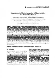
Functionally gradient titanium-aluminide composites produced by laser cladding J. H. A B B O U D ,
D. R. F. WEST, R. D. R A W L I N G S
Department of materials, Imperial College of Science, Technology and Medicine, London, SW7 2BP, UK The laser surface cladding of Ti-AI/TiB 2 composites was investigated as a means of producing a functionally gradient material on a commercially pure Ti substrate. Single and double layers were produced. The processing parameters were: 1.7 kW laser power, 3 mm beam diameter, 3 - 2 2 mm s -1 traverse speeds, 2.2-6.2 g min -1 powder flow rates. The results showed that functionally gradient Ti-AI/TiB 2 systems ~ 2 mm thick, with a progressive increase in the AI content from 0 to 35 w t % AI (50 at % AI) could be produced by vertically overlapping two clad layers using powder mixtures of selected compositions. Microstructural and compositional characterization were performed on single-layer and two-layer clads. Preliminary wear testing carried out on a laser surface Ti-AI/TiB 2 single-clad layer and on commercial-purity titanium demonstrated the beneficial effect of laser cladding on the wear resistance.
1. I n t r o d u c t i o n Irt coatings technology, multilayer processing can play an important role in achieving compatibility between the substrate and the surface system. As an extension of this procedure, attention is currently being given to the concept of bulk components with a controlled progressive change in their composition, structure and properties across their section; the term functionally gradient materials (FGMs) is applied in such cases. Examples that have been investigated include: Ni-ZrO2, NiCr ZrO2, Ti-TiN, Ni-NiO and Ti-TiC [1-3]. Various processing routes have been used thus far, including chemical and physical vapour deposition, powder metallurgy and plasma spraying. Recently, laser alloying/cladding has been used [4, 5] to deposit vertically overlapping layers of different compositions to produce a functionally gradient type of system. The process involves laser surface melting of a substrate, at the same time as a powder of a metal, ceramic or metal/ceramic mixture is blown into the laser-melted zone. The dimensions and the composition of the clad layers depend on processing parameters such as the traverse speed, the laser power, the beam diameter or the powder-feed rate. Abboud et al. [4] reported the use of a continuous wave CO2 laser and a powder-feeding technique in the production of three titanium aluminide layers, with a progressive increase in the A1 content in the range 15 ,-~ 30 wt %, by consecutive vertical deposition. Microstructural and compositional examination showed disordered martensite in the first layer and a mixture of dendrites of ~2 (Ti3AI) formed from [3, and % + 7 (TiA1) in the interdendritic regions in the third layer. Epitaxial growth was seen between the heat-affected zone and the first layer, and between the first and the second layer, while a planar zone was observed between the 0022-2461 9
1994 Chapman & Hall
second and the third layers. The microstructures were typical of rapid solidification and solid-state cooling. The injection of ceramic particles (such as TiB2) into the laser-melted zone of a commercial-purity Ti substrate, with partial dissolution of the ceramic particles, can lead to the formation of a composite layer [5, 6]. By mixing metal powder with ceramic powder in a selected ratio and laser surface depositing them on the surface of a substrate, functionally gradient composite layers can be produced. Jasim et al. [7] showed that by using three powder mixtures (namely, AI-10 wt % SiC, AI-30 wt % SiC, and A1-50 wt % SiC with a high-power CO2 laser, a functionally gradient region, with a progressive increase in aluminium and SiC, can be built up on a nickel-base-alloy substrate by three overlapping laser-processed layers. Partial dissolution of SiC led to a complex structure. The present work explored the possibility of using the same technique to build up titanium-aluminide composite layers on a commercial-purity titanium substrate with a progressive increase in the aluminium content. Aluminium was selected as a component for its aluminide-forming capability with titanium; this offers potential to improve the oxidation resistance. TiB z was chosen as the ceramic, to improve the wear resistance.
2. E x p e r i m e n t a l p r o c e d u r e A 2 kW CO 2 laser operated at 1.7 kW with a 3 mm beam diameter was used for laser cladding. The experimental arrangement has been described elsewhere [8-]. The traverse speed of the substrate (commercialpurity titanium) relative to the laser beam was varied between 3 and 22 mm s- 1; the flow rates of the premixed powders varied in the range 2.2-6.2 groin-1 3393
TABLE
I, The composition of the powder mixtures Composition (wt %)
Powder mixture
Ti
AI
B
Single-layer sample Double-layer sample Layer 1 Layer 2
82.2
10
7.8
72.2 62.2
20 30
7.8 7,8
The process was carried out under an effective shroud of argon gas to minimize contamination of the lasermelted region. The powder consisted of Ti, A1 and TiB 2 particles in the size range 50-75 p.m. A single layer and a double layer were produced. For the single layer, the mixture contained Ti-10A1/25 TiB 2 (wt %); for the double layer, the mixture for the first layer
contained Ti-20Al/25 TiB2, and the mixture for the second layer contained Ti-30A1/25 TiB~ (the compositions of Ti, A1 and B (wt %) are shown in Table I). After laser cladding, transverse and longitudinal sections were produced. Optical microscopy, scanning electron microscopy (SEM) with energy dispersive spectroscopy (EDS) and transmission electron microscopy (TEM) were used for the microstructural and compositional examination. The microhardness was also measured. Wear testing was carried out on a wear rig designed by Gofton et al. [9]. This rig consisted of a rotating circular base and, a cantilever beam powered by a separate motor, which (when restrained by guides) traversed the specimen over the base (which was covered with a SiC slurry, with a 75 gm particle size, in a roughly elliptical path. The wear rate was evalu-
15
~.~ 10 E
0
E O
0
r
0 (d)
200 400 600 800 1000 1200 Distancefrom thetop ofthe cladlayer(pm)
Figure 1 Laser surface cladding of Ti-10 wt % A1/25 wt % TiB 2 onto a commercial-purity Ti substrate with a single track: (a) transverse section, (b) longitudinal section, (c) SEM-BSI (back scattered image) showing TiB around TiB 2 and within the matrix, and (d) EDS X-ray analysis across the thickness.
3394
ated by measuring the sample weight before and after the test. Two samples were tested; one single clad layer of Ti-10 wt % A1-25 wt % TiB 2 and the commercialpurity Ti substrate. Both the clad layer and the substrate had the same surface area (4 mm wide and 7 mm long), were polished to a 1200 ~tm finish and were tested under the same conditions.
E
3
O
g2 E
3. R e s u l t s a n d d i s c u s s i o n Fig. la and b shows transverse and longitudinal sections, respectively, of a single clad track produced from a mixture containing 10 wt % A1-25 wt % TiB2, using a 1.7 kW laser power, a 3 mm beam diameter, a 5.3 mm s-1 traverse speed and a 3.5 g m i n - 1 powder flow rate. The track width and the thickness (distance from the top surface of the layer to the interface with the substrate) were 1.5 and 0.9 ram, respectively. A large amount of porosity, within the pore-size range 10 ~ 100 lain (diameter), was observed; this was not eliminated even when the powder was preheated before cladding. Such porosity was not seen during cladding of Yi-A1 [4]. Cracks were observed on the surface of all the tracks. The titanium and aluminium were completely dissolved, while the ceramic particles (TiB2) were partially dissolved leading to enrichment of the clad zone with boron. The distribution of the ceramic was not uniform; lack of adhesion in some regions at the interface between the clad layer and the substrate was also observed. SEM examination (Fig. lc) showed needle-like particles nucleated at the TiB2/matrix interface and within the matrix (assumed to be ~'). These particles appear lighter than TiB2 in SEM micrographs using a back-scattered mode and they have been identified as TiB. EDS X-ray analysis across the thickness (area analysis 5 x 10 ~tm) showed a nearly uniform aluminium content (Fig. ld) of 12 wt % which is close to the nominal powder composition. A slight dilution from the molten substrate was observed in the interface region. The microhardness of the matrix was approximately between 590 and 660 H v compared with approximately 190H v for the substrate. Decreasing the traverse speed or increasing the feed rate led to an increase in the width and thickness of the clad composite (Fig. 2a and b). Fig. 3a shows a transverse section of the two clad layers, with increasing At content, deposited vertically one above the other using a 1.7 kW laser power, a 3 mm beam diameter, a 4.2 g min-1 powder flow rate and a 5.3 mm s- 1 traverse speed. Powder mixtures Containing 20% A1/25 % TiB 2 and 30% A1/25% TiB 2 were used for the first and the second layers, respectively. Pores and cracks were observed as in the single track. A small amount of dilution (10 ~ 15%) between the substrate and the first layer was observed. EDS analysis across the thickness (Fig. 3b) showed an increase in the average A1 content from ,-~ 25 wt % in the first layer to ~ 35 wt % in the second layer. The microstructure of both layers showed partial dissolution of the TiB2 and nucleation of the needle-like particles of TiB at the TiB2/matrix interfaces and within the matrix. SEM examination of the first layer (Fig. 4a) showed primary TiB particles which are long and
0 0
10
(a)
20
30
T r a v e r s e s p e e d (mm s "1)
5
v
g o3
0
~ 2 (b)
I 3
i
I 4
i
I 5
P o w d e r f l o w rate (g min -1)
Figure 2 Laser surface cladding of Ti-10 wt % A1/25 wt % TiB 2 on a commercial-purity Ti substrate, single track, (a) dimensions versus traverse speed (1.7kW, 3ram and 4.2groin 1), (b) dimensions versus powder flow rate (1.7 kW, 3 mm and 5.3 mm s-1): (r~) width, and (~1,) thickness.
thick, and a eutectic of ~2/~2 -}- TiB crystals; the TiB particles in the eutectic were short and thin (Fig. 4a). TEM examination (Fig. 4b to e) showed that the TiB crystals had a faulted structure. Selected-area diffraction (SAD) from the % showed a hexagonal pattern with superlattice reflections. Dark-field imaging using these superlattice reflections showed antiphase domains boundaries (APBs). SEM examination of the second layer showed a complex matrix structure, which can be interpreted as being a mixture of %, y and TiB. The microhardness of the two clad layers increased considerably in comparison with the substrate (Fig. 5). This can be attributed to: (1) the matrix alloying with aluminium and to partial dissolution of the TiB 2 which leads to the formation of TiB crystals, (2) structure refinement as a result of the rapid solidification, and (3) absorption of oxygen (a previous analysis of similar samples showed an oxygen content of ~ 2300 p.p.m. (parts per million)). Fig. 6 shows an approximately linear relation between the weight loss in wear versus time for commercial-purity Ti substrate and a laser clad T i - 1 2 % AI/TiB 2 layer. It can be seen from Fig. 6 that laser 3395
40
30
o~ 20
10
0
0 (b)
400 800 1200 1600 2000 Distance from the top of the clad layer (pm)
Figure 3 Laser surface clading of Ti 10 wt % A1/25 wt % TiB 2 and Ti-20 wt % A1/25 wt % TiB/ on a commercial-purity Ti substrate, double layers: (a) an optical micrograph showing a transverse section of a F G M produced by vertical deposition of two Ti-A1 clad layers on a commercial-purity Ti substrate, and (b) EDS X-ray analysis across the thickness.
surface cladding improved the wear resistance (measured by the weight loss per unit time) by a factor of 2. SEM examination of the worn area of a clad layer subjected to a wear test for a very short period (less than ! min) showed that some of the scratches generated by the abrasive particles (in this case SiC) were stopped or deviated by the ceramic particles (TiB2). Fragmentation of the TiB 2, cracks at the TiB/~' interface and pull-out of TiB 2 particles were observed after long periods of wear testing (Fig. 7b).
Figure 4 Microstructures of double-layer samples: (a) SEM of the lower layer (Ti 25wt % AI) showing undissolved TiB z and TiB around TiB 2 and within the matrix, (b) a TEM micrograph showing large and small TiB crystals, (c) and (d) TEM micrographs (dark field) using a [0 1 10]~ 2 reflection showing APBs, and (e) a TEM micrograph (bright field) showing TiB with a faulted structure and ez/Ct~.
3396
800
7OO I
600 5"E E 500 400 3OO 200 100
, 0
I 400
,
I 800
,
I 1200
' 1600
2000
Distance from the top (/ira)
Figure 5 Microhardness versus distance across the thickness of two clad layers deposited vertically on each other (1.7 kW, 3 mm, 5 . 3 m m s 1, a n d 4 . 2 g m i n - L
200
160 E
v
120
O
_E
80
40
O
I
0
, I , I , I , I , 10
20
30
40
50
Figure 7 SEM micrographs of the worn surface of the Ti-12 wt % A1/TiB 2 layer: (a) after a short time period, showing TiB2 stopping and deviating scratches; and (b) after a long time period, showing fragmentation, cracking and pull-out.
Time(min) Figure 6 Weight loss versus time for ( 3 ) a commercial-purity Ti and (I~,) a laser surface Ti-12 wt % A1/25 wt % TiB2 clad layer single track (1.7 kW, 3 ram, 5.3 r a m s i and 4.2 gmin-1).
The likely solidification sequence of the composite layers can be deduced from consideration of the schematic representation shown in Fig. 8 of the Ti-A1-B system (based on binary-phase diagram data) [103. The liquid, enriched in B as a result of a partial solution of TiB 2, commenced solidification with the formation of TiB which appeared as a rim around the TiB 2 particles and as needles in the matrix. In the first layer, the liquid composition and temperature reached the liquid-~ TiB + (Ti A1) (13 solid solution) eutectic, when solidification was completed to form a relatively fine two-phase mixture. In the second layer, solidification was expected to commence by the formation of s-phase which then transformed to a mixture of ~2 ~" "~/, As previously reported [5], Ti3B 4 was not detected.
FGMs produced by laser cladding using a continuous powder-feed-rate technique consisted of a series of essentially discrete layers (tracks), with respect to the composition and structure, rather than a smooth gradient of these features. Control of the composition and structure of successive layers depends not only on the composition of the powder feed mixture, but also on
,_/
_,.
Ti
.X "~..\
1//7/0//I/// 10
/
/#
2.~\
Ti~B V"' ' ~ 20 Bcontent(wt %)
TiB2 30
Figure8 T i - A l - B composition triangle showing an approximate quantitative representation of a double-clad layer on a Ti substrate: X 1 and X z are the compositions of the powder feed mixtures ofTi + A1 + TiB2; A1 and A2 are the approximate average compositions of clad layers based on estimated dilutions; M 1 and M z are the approximate compositions of TiB + Ti-A1 solid-solution matrices based on estimated proportions of undissolved TiB 2. The subscripts 1 and 2 refer to the two layers. 3397
the laser processing parameters (for example, the power density and traverse speed) which control the dilution from the underlying layers and the solidification rate. Generally, in the first layer, minimum dilution from the substrate is desirable to achieve the required composition. The compositional changes during cladding can be illustrated by considering the double track with reference to the Ti-A1-B composition triangle (Fig. 8). The compositions of the feed mixtures are designated as X1 and X 2 (wt % of Ti, A1 and B) assuming no preferential losses of the elements in processing. The dilution by the substrate was around 15 wt % in track 1 (neglecting density differences), the average composition of track 1 can be located as A1 on the line joining Ti to X1. The point A1 must lie within the composition triangle made up by the three constituents TiB 2, TiB and Ti-Al(ss) (where (ss) indicates solid solution). The proportion of undissolved TiB 2 was ~ 15% and a lever rule calculation (extrapolation of the line from TiB 2 through A1) located the position of the YiB/Ti-Al(ss) side of the triangle; hence the A1 content of the Ti-Al(ss)+ TiB region was ~ 20 wt % (M 0 which is in reasonable agreement with the analysis value of 25 wt % A1 shown in Fig. 3b. Considering track 2, the same type of procedure was followed. Note that the average composition of the track A 2 lies on the line joining A 1 and X 2 at a position determined by the dilution (which is of the order of ~ 20%). The construction of the composition triangle was carried out taking a value of 20 wt % for the undissolved TiB 2. The A1 content of the Ti Al(ss) + TiB 2 mixture was found to be 34 %(M2), which is in close agreement with the analysis value of 35 wt % A1 (Fig. 3b) The same procedure can be applied to a single track or as a graphical means of designin9 a series of tracks to form a FGM, assuming that appropriate processing conditions can be established by experiment. The influence of the track geometry on the changes in composition and structure is an important consideration. In the case of single tracks fully overlapped, the first track is approximately part of a cylindrical surface; when the second track is superimposed, a conduction-limited melt zone develops in the previous track and in transverse section. The interface between the first and the second track is curved and it is not parallel to the original substrate surface. An initial layer of a F G M can be produced over a wide area by the conventional technique of depositing, side by side, partially overlapping tracks. Then, when a series of similar partially overlapping tracks is deposited on the first layer the interface between the two layers can be macroscopically parallel to the substrate in transverse section. The structure and properties of a F G M produced in this manner may differ to a certain extent to those found in the present work for fully over-
3398
lapping single tracks due to the remelting that takes place during the partial overlapping of the sideby-side tracks. From the viewpoint of the structural variations in F G M s it is clearly essential to understand the constitution of the alloy/composite system: this is particularly important in designing F G M s in complex multicomponent systems and in situations where certain phases may have an undesirable effect on properties. Laser-produced F G M structures are in a relatively rapidly solidified state; if subjected to high temperatures in service or to heat treatment, the effect of multicomponent diffusion and phase transformations on the structure must be taken in account.
4. Conclusions Cladding by feeding a powder mixture of Ti, A1 and TiB2 into a laser-generated melt pool on a titanium substrate can be used to produce vertical overlapping composite tracks of progressively increasing A1 content. However porosity and cracking are major difficulties, and further work is needed to eliminate these defects and to determine the process conditions required to obtain selected composition gradients. The method is envisaged as being more appropriate for multilayer surface coatings on local areas of a component, rather than for producing bulk F G M s of substantial dimensions.
Acknowledgements SERC is acknowledged for its financial support.
6. References 1. 2. 3. 4. 5. 6.
7. 8. 9. 10.
M. N I N O and S. MAEDA, I S I J Int. 30 (1990) 699. K. ATARASHIYA, K. K U R O K A W A , H. T A K A H A S H I and H. MATSUI, ibid. 30 (1990) 1130. T. HIRAI and SASAKI, J S M E Int. 34 (1991) 123. J . H . ABBOUD, D. R. F. WEST and R. D. RAWLINGS, Mater. Sci. Technol, to be published. J . H . A B B O U D and D. R. F. WEST, J. Mater. Sci. Lett. 13 (1994) 457 ldem., Seventh World Conference on Titanium, Titanium 1992 Science and Technology, June 29-July 2, 1992, San Diego, California, ed. F. H. Froes and I. L. Caplan, Vol III, (TMS, 1992) pp. 2503-2510. K. M O H A M M E D JASIM, R. D. R A W L I N G S and D. R. F. WEST, J. Mater. Sci. 28 (1993) 2820-2826. T. T A K E D A , W. M. STEEN and D. R. F. WEST, Proc. Conf. LIM2, (IFS Bedford, 1985). I. G O F T O N , R. D. R A W L I N G S and P. S. ROGERS (1989) unpublished work. J. L. MURRAY, "Binary phase diagrams", edited by T. B. Massalski, (American Society for Metals, Metals Park, Ohio, 1986) pp. 392 and 595.
Received 16 November 1993 and accepted 3 February 1994