Fusion Simulation Project Workshop Report Co-Chairs
Arnold Kritz (Lehigh University) David Keyes (Columbia University) Fusion Simulation Project Panels Status of Physics Components
Required Computational and Applied Mathematics Tools
∗ Scott Parker, U. Colorado ∗ Cynthia Phillips, PPPL ∗ Xianzhu Tang, LANL
∗ Phil Colella, LBNL ∗ David Keyes, Columbia ∗ Patrick Worley, ORNL
Project Structure and Management
Integration and Management of Code Components
∗ Phil Colella, LBNL ∗ Martin Greenwald, MIT ∗ David Keyes, Columbia ∗ Arnold Kritz, Lehigh U.
∗ Dan Meiron, Cal Tech ∗ Tom Rognlien, LLNL ∗ Andrew Siegel, ANL/U. Chicago
Glenn Bateman, Lehigh U. Paul Bonoli, MIT C-S Chang, NYU Ron Cohen, LLNL Pat Diamond, UCSD Guo-Yong Fu, PPPL Chris Hegna, U. Wisconsin Dave Humphreys, GA George Tynan, UCSD
Don Batchelor, ORNL Vincent Chan, GA Bruce Cohen, LLNL Steve Jardin, PPPL David Schissel, GA Dalton Schnack, U. Wisconsin Fran¸cois Waelbroeck, U. Texas Michael Zarnstorff, PPPL
Jeff Candy, GA Luis Chacon, LANL George Fann, ORNL Bill Gropp, ANL Chandrika Kamath, LLNL Valerio Pascucci, LLNL Ravi Samtaney, PPPL John Shalf, LBNL
Michael Aivazis, CalTech Rob Armstrong, Sandia David Brown, LLNL John Cary, Tech-X Lang Lao, GA Jay Larson, ANL Wei-Li Lee, PPPL Doug McCune, PPPL Ron Prater, GA Mark Shephard, RPI
* Indicates Fusion Simulation Project Committee Member
Abstract The mission of the Fusion Simulation Project is to develop a predictive capability for the integrated modeling of magnetically confined plasmas. This FSP report adds to the previous activities that defined an approach to integrated modeling in magnetic fusion. These previous activities included a Fusion Energy Sciences Advisory Committee panel that was charged to study integrated simulation in 2002. The report of that panel [Journal of Fusion Energy 20, 135 (2001)] recommended the prompt initiation of a Fusion Simulation Project. In 2003, the Office of Fusion Energy Sciences formed a steering committee that developed a project vision, roadmap, and governance concepts [Journal of Fusion Energy 23, 1 (2004)]. The current FSP planning effort involved forty-six physicists, applied mathematicians and computer scientists, from twenty-one institutions, formed into four panels and a coordinating committee. These panels were constituted to consider: Status of Physics Components, Required Computational and Applied Mathematics Tools, Integration and Management of Code Components, and Project Structure and Management. The ideas, reported here, are the products of these panels, working together over several months and culminating in a three-day workshop in May 2007.
Contents
Executive Summary
i
1 Introduction and Motivation
1
1.1
Motivation . . . . . . . . . . . . . . . . . . . . . . . . . . . . . . . . . . . .
5
1.2
Role of Petascale Computing . . . . . . . . . . . . . . . . . . . . . . . . . .
9
1.3
Verification and Validation . . . . . . . . . . . . . . . . . . . . . . . . . . . 10
1.4
Deliverables . . . . . . . . . . . . . . . . . . . . . . . . . . . . . . . . . . . 11
1.5
Organization of the Report . . . . . . . . . . . . . . . . . . . . . . . . . . . 12
2 Scientific Issues 2.1
2.2
13
Critical Issues for Burning Plasma Experiments . . . . . . . . . . . . . . . 16 2.1.1
Disruption effects and mitigation . . . . . . . . . . . . . . . . . . . 16
2.1.2
Pedestal formation and transient heat loads on the divertor . . . . . 17
2.1.3
Tritium migration and impurity transport . . . . . . . . . . . . . . 18
2.1.4
Performance optimization and scenario modeling . . . . . . . . . . . 20
2.1.5
Plasma feedback control . . . . . . . . . . . . . . . . . . . . . . . . 22
Physics Components Essential for Integrated Burning Plasma Simulations . . . . . . . . . . . . . . . . . . . . 24 2.2.1
Core and edge turbulence and transport . . . . . . . . . . . . . . . 25
2.2.2
Large-scale instabilities . . . . . . . . . . . . . . . . . . . . . . . . . 27
2.2.3
Sources and sinks of heat, momentum, current and particles . . . . 29
2.2.4
Energetic particle effects . . . . . . . . . . . . . . . . . . . . . . . . 31
3 Verification and Validation 3.1
3.2
37
Verification . . . . . . . . . . . . . . . . . . . . . . . . . . . . . . . . . . . 38 3.1.1
Code verification . . . . . . . . . . . . . . . . . . . . . . . . . . . . 38
3.1.2
Solution verification
. . . . . . . . . . . . . . . . . . . . . . . . . . 39
Validation . . . . . . . . . . . . . . . . . . . . . . . . . . . . . . . . . . . . 39 3.2.1
Model validation . . . . . . . . . . . . . . . . . . . . . . . . . . . . 41
3.2.2
Predictive estimation . . . . . . . . . . . . . . . . . . . . . . . . . . 41
4 Integration and Management of Code Components 4.1
4.2
4.3
43
Integration Requirements for FSP Software . . . . . . . . . . . . . . . . . . 44 4.1.1
Integration of diverse physical simulation capabilities and modalities 44
4.1.2
Multiscale modeling
4.1.3
Adaptivity . . . . . . . . . . . . . . . . . . . . . . . . . . . . . . . . 45
4.1.4
Implicit algorithms . . . . . . . . . . . . . . . . . . . . . . . . . . . 45
4.1.5
Usability and flexibility . . . . . . . . . . . . . . . . . . . . . . . . . 46
. . . . . . . . . . . . . . . . . . . . . . . . . . 45
Challenges of Multiphysics Coupling . . . . . . . . . . . . . . . . . . . . . 46 4.2.1
Taxonomy of multiphysics coupling . . . . . . . . . . . . . . . . . . 46
4.2.2
Multiscale coupling . . . . . . . . . . . . . . . . . . . . . . . . . . . 49
4.2.3
Opportunities in fusion computation coupling . . . . . . . . . . . . 50
Code Coupling Strategies . . . . . . . . . . . . . . . . . . . . . . . . . . . . 51 4.3.1
Component architectures . . . . . . . . . . . . . . . . . . . . . . . . 51
4.4
4.3.2
Component frameworks
. . . . . . . . . . . . . . . . . . . . . . . . 53
4.3.3
Strategies for incorporating legacy codes and interfaces . . . . . . . 55
4.3.4
Structured mesh frameworks . . . . . . . . . . . . . . . . . . . . . . 56
4.3.5
Unstructured mesh frameworks . . . . . . . . . . . . . . . . . . . . 59
Status of Fusion Simulation Prototype Centers . . . . . . . . . . . . . . . . 60 4.4.1
CPES . . . . . . . . . . . . . . . . . . . . . . . . . . . . . . . . . . 60
4.4.2
FACETS . . . . . . . . . . . . . . . . . . . . . . . . . . . . . . . . . 61
4.4.3
SWIM . . . . . . . . . . . . . . . . . . . . . . . . . . . . . . . . . . 62
4.5
Fusion Code Integration Projects in Europe and Japan . . . . . . . . . . . 63
4.6
Software Management . . . . . . . . . . . . . . . . . . . . . . . . . . . . . 63 4.6.1
Revision control . . . . . . . . . . . . . . . . . . . . . . . . . . . . . 64
4.6.2
Build system . . . . . . . . . . . . . . . . . . . . . . . . . . . . . . 65
4.6.3
User and developer communication . . . . . . . . . . . . . . . . . . 65
4.6.4
Issue tracking . . . . . . . . . . . . . . . . . . . . . . . . . . . . . . 65
4.6.5
Testing . . . . . . . . . . . . . . . . . . . . . . . . . . . . . . . . . . 66
4.6.6
Versioning/release management . . . . . . . . . . . . . . . . . . . . 66
4.6.7
Documentation . . . . . . . . . . . . . . . . . . . . . . . . . . . . . 66
4.7
Project Phasing and Deliverables . . . . . . . . . . . . . . . . . . . . . . . 67
4.8
Code Integration and Managment Conclusions . . . . . . . . . . . . . . . . 68
5 Mathematical and Computational Enabling Technologies 5.1
5.2
71
Applied Mathematics and Numerical Methods . . . . . . . . . . . . . . . . 71 5.1.1
Challenges and state-of-the-art in computational plasma physics . . 72
5.1.2
Enabling technologies . . . . . . . . . . . . . . . . . . . . . . . . . . 76
Data Management and Analysis . . . . . . . . . . . . . . . . . . . . . . . . 78
5.3
5.2.1
Managing large-scale simulated and experimental data . . . . . . . 79
5.2.2
Scientific data mining . . . . . . . . . . . . . . . . . . . . . . . . . . 81
5.2.3
Scientific data visualization and analytics . . . . . . . . . . . . . . . 83
5.2.4
Workflow technology . . . . . . . . . . . . . . . . . . . . . . . . . . 86
Computer System Performance . . . . . . . . . . . . . . . . . . . . . . . . 87 5.3.1
Performance engineering . . . . . . . . . . . . . . . . . . . . . . . . 88
5.3.2
Performance scaling and scalability . . . . . . . . . . . . . . . . . . 90
6 Project Management and Structure
95
6.1
Management Issues . . . . . . . . . . . . . . . . . . . . . . . . . . . . . . . 95
6.2
A Sample FSP Structure . . . . . . . . . . . . . . . . . . . . . . . . . . . . 97
Appendix A: Acronyms and Definitions
101
Appendix B: Workshop Agenda
105
Appendix C: Workshop Attendees
107
Executive Summary The mission of the Fusion Simulation Project (FSP) is to develop a predictive capability for integrated modeling of magnetically confined burning plasmas. The FSP provides an opportunity for the United States to leverage its investment in ITER and to further the U.S. national interests in the development of fusion as a secure and environmentally attractive source of energy. The predictive simulation capability provided by the FSP will enhance the credibility of proposed U.S. experimental campaigns. In addition, FSP will enhance the understanding of data from burning plasma discharges and provide an opportunity for scientific discovery. The knowledge thus gained will be beneficial during ITER operation as well as in the design, development and operation of future demonstration fusion power plants. The integrated modeling capability developed through the FSP will be an embodiment of the theoretical and experimental understanding of confined thermonuclear plasmas. The ultimate goal is to develop the ability to predict reliably the behavior of plasma discharges in toroidal magnetic fusion devices on all relevant time and space scales. In addition to developing a sophisticated computational software suite for integrated modeling, the FSP will carry out directed research in physics, computer science, and applied mathematics in order to achieve its goals. FSP will involve collaboration between software developers and researchers funded by OFES and OASCR and will also forge strong connections with experimental programs in order to validate the models. The complexity of the most advanced multiphysics nonlinear simulation models will require access to petascale-class, and ultimately exascale-class, computer facilities in order to span the relevant time and space scales. The FSP will capitalize on and illustrate the benefits of the DOE investments in high-performance computing, which provide the platforms for the demanding calculations entailed by the project. The Fusion Simulation Project is driven by scientific questions, programmatic needs and technological opportunities. Five critical scientific issues are identified as “targets” for the project. These critical issues are: 1) Disruption effects, including avoidance and mitigation; 2) Pedestal formation and transient divertor heat loads; 3) Tritium migration and impurity transport; 4) Performance optimization and scenario modeling; and 5) Plasma feedback control. These issues are particularly urgent for the burning plasma physics program and for successful operation of the ITER experiment. The FSP will allow researchers to carry out the ITER experimental program more efficiently in order to make optimum use of the finite number of ITER pulses. In addition, the FSP could enable new modes of operation, with possible extensions of performance and improvements to the fusion reactor concept. FSP will increase the scientific return on the U.S. investment in ITER through improvements in data analysis and interpretation. FSP builds on a strong base of scientific accomplishments in plasma physics, computer science, and applied mathematics and will rely on the opportunities afforded by ongoing research in each of these areas. This FSP report adds to the previous activities that defined an approach to integrated modeling in magnetic fusion. These previous activities included a FESAC panel that was charged to study integrated simulation in 2002. Its report adopted by the full FESAC in December of that year [http://www.isofs.info/FSP_Final_Report.pdf], recommended the prompt initiation i
of a Fusion Simulation Project. In 2003, OFES formed a steering committee that developed a project vision, roadmap, and governance concepts [Journal of Fusion Energy 23, 1 (2004)]. The current FSP planning effort involved over 40 scientists, formed into four panels and a coordinating committee. The ideas, reported here, are the products of these groups, working together over several months and culminating in a three-day workshop. As envisioned by workshop participants, the FSP will encompass a research component and a production component, the latter with a large user base of individuals who are not necessarily code developers. The physics covered by FSP will include turbulence and transport, macroscopic equilibrium and stability, heating and current drive, energetic particles, plasma-wall interactions, atomic physics and radiation transport. Plasma control, including coils and current carrying structures and all other external actuators and sensors, will also be modeled. While most technology issues, such as those associated with structural materials, neutron damage or tritium breeding, are currently considered outside the scope of FSP, a parallel effort in those areas should be considered. The research component of FSP will focus on coupling and integration issues, associated with multiscale and multiphysics models, with the necessary computer science and applied mathematics tools required for coupling and integration. The production component will provide stable versions of the codes and infrastructure, which will be widely deployed and utilized in ongoing scientific research. Modern software engineering techniques will be particularly important in establishing a stable production capability. It is crucial to note that the currently available physics models, though highly developed, are still far from complete. There is a consensus that the physics models are sufficiently developed and tested to begin serious efforts toward integration, but it is quite clear that the FSP cannot achieve its goals without continuing advances in the underlying theoretical, experimental and computational physics. The physics governing magnetic fusion plasmas involves an enormous range of temporal and spatial scales and, as a result, simulations are not tractable by brute force. One approach to the problem is based on scale separation, which allows solutions to well defined subsets of the overall physical system. However, there are many critical science issues for which strong interactions between these subsets cannot be ignored, even approximately. For example, five critical issues have been identified, which can be addressed with a reasonable extrapolation beyond the present capabilities in the time period of the project with the new resources requested. For each of these critical issues, the essential problem is that strongly coupled, multiscale and multiphysics integration must be addressed. Issues in computer science and applied mathematics, which must be addressed to enable the required modeling, have been identified. The major computer science issues include development of a software component architecture that allows large-scale integration of high-performance simulation codes and efficient exploitation of high-performance computing hardware. The current state-of-the-art tools in data management and analysis can benefit FSP in the early years; however, further advances are necessary to make these tools suitable for the size and characteristics of data from both simulations and experiments. In applied mathematics, improved equation solvers, scalable to very large problems must be further developed, including advanced adaptive mesh and pseudo-spectral methods. There will be a need for new or updated algorithms to provide consistent, converged, accurate solution of coupled multiphysics problems.
ii
If the codes produced by the FSP are to be useful, their development must be accompanied by a substantial effort to ensure that they are correct. This process is usually called verification and validation. Verification assesses the degree to which a code correctly implements the chosen physical model, which is essentially a mathematical problem. Validation assesses the degree to which a code describes the real world. Validation is a physical problem that can be addressed only by comparison with experiments. Both of these elements are essentially confidence-building exercises that are required if the predictions of the code are to be trusted. Verification and validation will be a strong element of the FSP and will require close connections with the theoretical and experimental communities The FSP will be, by a very large margin, the largest computational collaboration ever attempted in the magnetic fusion program. Its unprecedented scope and focus will require strong, mission oriented management. By drawing on experiences from other large computational projects, such as the Advanced Strategic Computing (ASC) program of the NNSA and the Community Climate System Model (CCSM) led by NCAR, as well as the large fusion experimental programs, management principles are defined. These principles will result in establishing lines of responsibility and resource management, mechanisms for coordination and decision making, and structures for external input and oversight. An example of a possible management structure is described. Deliverables for the FSP are defined for intervals of 5, 10 and 15 years from the start of the project. The basic deliverable after 5 years will be a powerful, integrated whole-device modeling framework that uses high-performance computing resources to include the most upto-date physics components. This deliverable will be accompanied by stringent verification methods and validation capabilities, synthetic diagnostics, experimental data reconstruction to facilitate comparison with experiment, as well as state-of-the-art data archiving and data mining capabilities. At the end of 10 years, new capabilities will be added in order to develop an advanced and thoroughly tested simulation facility for the initial years of ITER operation. The new capabilities will include the use of high-performance computations to couple turbulence, transport, large-scale instabilities, radio frequency, and energetic particles for core, edge and wall domains across different time and spatial scales. Pair-wise coupling will evolve to comprehensive integrated modeling. The facility will include the ability to simulate active control of fusion heated discharges. At the end of 15 years, the Fusion Simulation Project will have developed a unique world-class simulation capability that bridges the gap between first-principles computations on microsecond timescales and whole-device modeling on the timescales of hundreds of seconds. This capability will yield integrated high fidelity physics simulations of burning plasma devices that include interactions of all the physical processes. It is concluded, after considering the needs of the fusion program and the emerging opportunities, that now is the appropriate time for aggressively advancing the Fusion Simulation Project. Key scientific issues are identified. These issues will be addressed by integrated modeling that incorporates advances in plasma physics, computer science, applied mathematics, and high-performance petascale computing. It is recognized that verification and validation are essential. The report outlines technical challenges and a plan for approaching the project including
iii
the project structure and management. The importance of building on healthy base programs in OFES and OASCR is recognized, as well as the requirement to coordinate with the ITER organization and the U.S. Burning Plasma Organization (BPO). The Fusion Simulation Project agenda for applied mathematics and computer science lies squarely on top of the ten-year vision statement “Simulation and Modeling at the Exascale for Energy, Ecological Sustainability and Global Security” prepared in 2007 by the DOE’s Office of Advanced Scientific Computing Research, whose participation will be crucial to the success of the FSP. This statement articulates three characteristics of opportunities for exascale simulation: (1) System-scale simulations integrating a suite of processes focusing on understanding whole-system behavior, going beyond traditional reductionism focused on detailed understanding of components; (2) interdisciplinary simulations incorporating expertise from all relevant quarters and observational data; and (3) validated simulations capitalizing on the ability to manage, visualize, and analyze ultra-large datasets. Supporting these opportunities are four programmatic themes including: (1) Engagement of top scientists and engineers to develop the science of complex systems and drive computer architectures and algorithms; (2) investment in pioneering science to contribute to advancing energy, ecology, and global security; (3) development of scalable algorithms, visualization, and analysis systems to integrate ultra-scale data with ultra-scale simulation; and (4) build-out of the required computing facilities and an integrated network computing environment. The Fusion Simulation Project outlined in this report is an ideal vehicle for collaboration between the OFES and OASCR because it embodies the ten-year plans of both organizations, and magnetically confined fusion energy is as close as any application to OASCR’s objectives. Furthermore, the SciDAC program has already created several energetic and communicating interdisciplinary research groups that combine OFES and OASCR researchers. Jointly supported simulation teams have already scaled nearly to the end of available computing environments, are assessing lessons learned, and are poised to take the next steps.
iv
Chapter 1
Introduction and Motivation The world fusion program has entered a new era with the construction of ITER, which will be the first magnetic fusion experiment dominated by the self-heating of fusion reactions. Because of the need to operate burning plasma experiments such as ITER near disruptive limits to achieve the scientific and engineering goals, there will be stringent requirements on discharge design and simulation. The control and optimization of burning plasmas and future prototype fusion reactors will therefore require a comprehensive integrated simulation capability that is fully verified and validated against available experimental data. Simulations, using this capability, will also provide an opportunity for scientific discovery through advanced computing. It will be essential to use comprehensive whole-device computer simulations to plan and optimize discharge scenarios since each ITER discharge will cost approximately one million dollars. Stringent requirements result in the need for accurate predictions: In particular, for the edge transport barrier that enhances core plasma confinement; for edge instabilities that cause transient heat loads on the divertor; and for turbulence that leads to the transport of energy, momentum and particles from the core and edge regions of the tokamak. As a consequence, the ITER experimental program has recognized the need for a comprehensive simulation code as an essential part of the scenario planning process [ITER COP report N 94 PL 4 (01-6-15) R1.0, page 26]: Very careful planning is essential for ITER operation. The permissible parameters and conditions will have to be authorized in advance and the operation must be within the envelope of the approved conditions. In order to assess the planned operation, a comprehensive simulation code, including both engineering and physics, is essential. It will have to be developed during the construction phase, tested during the commissioning phase and improved during operation. This code will be essential also during operation for real-time or almost realtime analyses and display to understand plasma and machine behavior and to optimize operation conditions.
1
CHAPTER 1. INTRODUCTION AND MOTIVATION The need for a comprehensive set of predictive models, validated with data from existing experiments and ITER, has long been recognized in the U.S. fusion program. In 2002, the Integrated Simulation of Fusion Systems (ISOFS) committee formulated a plan for the development of such a capability, termed the Fusion Simulation Project (FSP). The overarching goal of FSP was well expressed in the committee report [http://www.isofs.info/FSP_Final_Report.pdf]: The ultimate goals of the Fusion Simulation Project are to predict reliably the behavior of plasma discharges in a toroidal magnetic fusion device on all relevant time and space scales. The FSP must bring together into one framework a large number of codes and models that presently constitute separate disciplines within plasma science . . .
The FSP provides an opportunity for the United States to leverage its investment in ITER and to further the national interest in the eventual development of domestic sources of energy. Access by each international partner for experimental campaigns on ITER will involve a highly competitive scientific review process. The predictive simulation capability provided by the FSP will enhance the credibility of proposed U.S. experimental campaigns. In addition, the FSP will enhance the scientific understanding of data from ITER discharges. The knowledge thus gained will be beneficial during ITER operation as well as in the design, development and operation of any future DEMO-class device. During the last five years, the concept of the Fusion Simulation Project has matured through the deliberations of three committees comprised of physicists, mathematicians, and computer scientists. During this time the FSP vision has been refined through experience and increasing capability. In particular, there have been extraordinary advances in computer hardware, software engineering, and the ability to simulate tokamak plasmas. High-performance computers now allow massively parallel computations on tens of thousands of processors with distributed memory. Improved computational techniques have increased the speed of high-end scientific simulations by five orders of magnitude over the 19-year history of the Gordon Bell Prize. State-of-the-art computer simulations based on first principles are now used to study turbulence, radio frequency heating and large-scale instabilities in tokamak plasmas. The Fusion Simulation Project will use high-performance computers for accurate and reliable comprehensive simulations of magnetically confined plasmas. Well defined, realizable goals have been identified that are keyed to the needs of ITER and commercially viable demonstration (DEMO) projects. The vision for the first 5 years after the initial FSP design phase, which is in time to prepare for ITER first operation, is: To assemble a new powerful integrated whole-device modeling framework that uses high-performance computing resources for the simulation of tokamak plasmas. This simulation framework will allow interoperability of state-of-the-art physics components running on the most powerful available computers, together with the flexibility to incorporate less demanding models so that the computational scale can be tailored appropriately to the particular study. The fidelity of the models will be verified using first-principles simulations on leadership2
CHAPTER 1. INTRODUCTION AND MOTIVATION class computers. The project will develop an infrastructure for user interface, visualization, synthetic diagnostics, data access, data storage, data mining, and validation capabilities that will allow FSP resources to be configured to perform all of the required fusion simulation tasks: timeslice analysis, interpretive experimental analysis, predictive plasma modeling, advancement of fundamental theoretical understanding, and operational control. During the first 5 years, there will be focus on a limited number of problems for which advanced simulation capability can provide exciting scientific deliverables that substantially impact realistic predictive capabilities. At the end of this 5-year period, basic capabilities will be in place to perform the calculations needed to support ITER diagnostics, plasma control and auxiliary systems design, and review decisions. The integrated plasma simulator at this stage will be capable of performing entiredischarge modeling including required coil currents and voltages. Modular plug-in units to the simulator will describe, using reduced-order (as opposed to first-principles) models, all classical and anomalous transport coefficients, all heating, particle, current drive, and momentum sources, as well as large-scale instability events such as sawtooth oscillations, magnetic island growth, and edge localized modes. In addition to the whole-device simulator, there will be a number of state-of-the-art codes, designed to solve more first-principles equations, that will be used for timeslice analysis. These fundamental codes will be employed to better understand the underlying physical processes and, in doing so, to refine the modules in the simulator. They will also be used for such ITER-directed tasks as developing mitigation methods for edge localized modes and disruptions, and for predicting the effects of energetic particle modes. At this stage, the simulator will be capable of basic control system modeling involving coil currents, density control, and burn control. In addition, computational synthetic diagnostics will allow the simulation codes to be used for diagnostic development. In parallel with the development of simulation capabilities, the FSP will foster the development of leading-edge scientific data management, data mining, and data visualization capabilities. Such capabilities are currently integral to the Scientific Discovery through Advanced Computing (SciDAC) program and to the FSP prototype centers. The significance of these capabilities extends beyond the ability to manipulate the results of simulation data at the petascale. ITER experimental data sets will also approach scales that defy contemporary tools for archiving and understanding. Automated data mining tools to detect the onset of instabilities in their incipient stages in order to apply mitigation strategies will complement simulation-based control strategies. Advanced software tools for understanding and managing large experimental datasets are integral to the validation goals of the FSP, and they open the door to data assimilation — the prospect of reducing uncertainty in simulations by penalizing the departure of functionals of the simulation from experimental observables. High-end scientific computational facilities provide an environment to host experimental data and to facilitate the interaction of the modeler and experimenter by enabling comparisons of the respective data products. The 10-year vision, in time to prepare for deuterium-tritium operations with ITER, is: To develop a simulation facility that is required to meet the scientific and engineering objectives for ITER throughout the remainder of its operational lifetime.
3
CHAPTER 1. INTRODUCTION AND MOTIVATION The system will allow for self-consistent complex interactions that involve coupling of physical processes on multiple temporal and spatial scales using high-performance software on leadershipclass computers. The experience gained from FSP pilot projects and advances in the FSP research component and the OFES and OASCR base programs will result in a comprehensive simulation framework. The framework will include coupling of extended magnetohydrodynamics, core and edge turbulence, long-timescale transport evolution, source models, energetic particles and coupling of core and edge physics at the state-of-the-art level. Advanced component models will reflect advances in theory and algorithms, as well as verification and validation using comparisons with existing experiments and the early phase of operation on ITER. Validated simulations will cover all the critical phenomena for tokamak operation, disruptions, energetic particle stability and confinement, turbulent transport, and macro stability. The system will be optimized for the most powerful computer platforms using the most efficient computational frameworks to accommodate the increased demands of multiscale, multiphysics coupling, new computer architectures, and experience gained with user needs. FSP codes will be capable of comprehensive integrated time-slice analysis and will be used to develop sophisticated control systems that are actuated by heating, fueling, and current drive systems as well as external 3D magnetic coils. Examples of control systems include the use of radio frequency current drive to control monster sawteeth and to prevent magnetic island growth, as well as the use of external 3D magnetic fields or rapid pellet injection to control edge localized modes. It is expected that FSP simulation codes will lead to significant increases in the understanding of many complex processes, including the formation of the edge pedestal and the mechanisms that lead to plasma disruptions. These developments will lead to improved simulation modules and to more realistic prediction of plasma scenarios. During this time period, the validation effort will switch from primarily pre-ITER experiments to ITER itself. The 15-year vision, using the experience gained after approximately 5 years of operation with deuterium and tritium in ITER, is: To develop a simulation facility that will be sufficiently well validated to extrapolate with confidence to a DEMO reactor based on the tokamak concept or other more advanced magnetic confinement concepts. By the end of 15 years, FSP will have developed a world-class simulation capability that will be used in many ways to get the maximum benefit from ITER. The simulation capability will be used to identify optimal operation modes for burning plasma experiments that combine good confinement, high fusion gain, and freedom from disruptions. This capability will be used extensively in the experimental discharge design for ITER as well as analyzing experimental data and comparing it with predicted simulation data. The capability will also be used to tune further the many control systems in ITER. It is expected that the sophisticated and well validated simulation tool that is developed by this project will play an indispensable role in the design of next-generation fusion devices such as DEMO and beyond.
4
CHAPTER 1. INTRODUCTION AND MOTIVATION As an ITER partner, the U.S. should be capable of matching its investment in the ITER experiment with the benefits of high-end computational platforms. The key advantage that the U.S. will derive from FSP is the software that is capable of exploiting high-performance computer hardware and the experience base of the modeling community resulting from comprehensive computer simulations. The Fusion Simulation Project requires well supported theory and experimental fusion programs. The OFES and OASCR base programs, in particular, are needed to provide improvements to the physics models, the algorithms and the computer science that are at the foundation of FSP components. Improved models are essential for physics fidelity of FSP simulations. Improved diagnostics in the experimental program are needed to provide accurate experimental data for the validation of FSP simulation results. It is anticipated that FSP personnel will work closely with plasma physics theoreticians and experimentalists at each stage in the development of the project. New contributions and scientific discovery can result from significant advances in physics models, algorithms, software and computer hardware. A substantial increase in funding is required for FSP to reach its goals while maintaining a strong base research program.
1.1
Motivation
The driving force for the Fusion Simulation Project is the urgent need for a burning plasma simulation capability that will be addressed with emerging petascale computer capability and the assembled knowledge base of DOE OFES and OASCR programs (Figure 1.1). With respect to ITER, the highest level FSP goal is to contribute to making ITER a successful project. Simulations must support both operational and scientific requirements in order to exploit the largest and most expensive scientific instrument ever built for fusion plasma research. In the long run, operational needs can only be answered through improved scientific understanding. Specifically, simulations would: Allow researchers to carry out the experimental program more efficiently, to make the best use of the finite number of ITER pulses. The ITER specification is for 30,000 pulses over its lifetime. Operational considerations will probably impose limits of 1,000 to 2,000 pulses per year. Since it is expected that operational time on ITER will be highly oversubscribed, there will many more experiments proposed than machine time available (just as on current facilities). Since the operational space that must be explored is far too large to search exhaustively, researchers need tools for scenario modeling and performance prediction to guide experiments along the most promising avenues. Modeling will also be used to reduce risks to the ITER facility by predicting and avoiding interactions and disruptions that can stress the mechanical or electrical systems. For example, by integrating high-quality physics modules together with models for control systems and power supplies, codes can help operators reduce the alternating current losses in the poloidal field coils and thus reduce the chances of a quench in the superconductor windings. The relatively crude integrated
5
CHAPTER 1. INTRODUCTION AND MOTIVATION
Figure 1.1: The Fusion Simulation Project is the result of a unique convergence. modeling codes available today will need to be dramatically improved, commensurate with the added complexity and cost of the ITER facility. This improved capability is particularly important since ITER will be the first magnetic fusion experiment to be dominated by selfheating. This plasma regime is fundamentally new, with stronger self-coupling and weaker external control than ever before. The ITER start-up phase is particularly challenging because of the engineering limits of the superconducting coils, the greater distance between these coils and the plasma, and the increased electrical conductivity of the vacuum vessel and structures. Operators will have to guide the discharges along a path that accesses and maintains high confinement (H-mode) using the available auxiliary heating until the plasma density and temperature are high enough for fusion power to become significant. For advanced operating modes, the current profile will need to be carefully controlled through application of external current drive and the modification of plasma profiles to tailor bootstrap current while taking into account resistive diffusion of the parallel electric field. There will be a very high pay-off for using FSP capabilities to simulate the ITER start up phase.
6
CHAPTER 1. INTRODUCTION AND MOTIVATION Disruptions are violent instabilities that terminate the plasma discharge, producing large transient forces on adjacent structures. High-performance fusion plasmas must necessarily operate near disruptive limits but cannot exceed them. Since ITER will be designed to withstand only a limited number of full-current disruptions, it is imperative to use computer modeling to help determine the disruptive limits, rather than relying on a purely empirical experimental approach. Also, it is essential to develop disruption mitigation techniques so that when a disruption does occur, its damage to the first-wall and divertor plates will be minimal. Modeling codes will be indispensable for this purpose. Modeling can also be used to predict pedestal dynamics and to avoid regimes with large ELMs, or to develop mitigation techniques if they do occur. Enable new modes of operation, with possible extensions of performance. Validated integrated models will enable researchers to extrapolate from existing confinement experiments to burning plasma experiments. A comprehensive modeling capability will facilitate the development of advanced tokamak regimes that will extend ITER’s performance and will help bridge the gap to a DEMO fusion reactor. The combination of enhanced stability, transport barrier formation, and bootstrap current drive make these regimes very difficult to establish experimentally in ITER without the comprehensive modeling codes proposed for this project. Increase the scientific return on the government’s investment in the project through improvements in data analysis and interpretation. Just as simulations will be used to motivate and design experiments on ITER, simulations will be crucial in interpreting measurements, analyzing results and extracting scientific knowledge. Although highly sophisticated, plasma diagnostics can sample only a very small portion of the available phase space. Codes will be instrumented with “synthetic diagnostics” that provide a bridge between measurement and simulations that will allow the measurements to be understood in context. Well designed experiments will be used to validate models and allow them to be used for prediction. The FSP will also contribute to development and deployment of technologies for data management, visualization and sharing, and will be used for scientific discovery. Provide an embodiment for the scientific knowledge collected on ITER. To move beyond ITER toward commercialization of fusion energy, the knowledge gained by research must be captured and expressed in a form that can be used to design future devices. This is particularly critical for expensive nuclear facilities such as the component test facilities and demonstration power plants, which will be unforgiving with respect to performance projections and operational limits. The Fusion Simulation Project, which will focus on tokamak physics, will naturally contribute to the basic understanding of innovative confinement concepts, including those with three-dimensional geometry. This generality is crucial if the U.S. wishes to hold open an option in which a non-tokamak DEMO follows ITER, without an equivalent burning plasma experiment for that concept. A set of validated, predictive models from the FSP will embody the scientific and technological understanding of fusion systems and allow fusion energy to go forward on a firm basis.
7
CHAPTER 1. INTRODUCTION AND MOTIVATION There are further goals for the FSP that align with the OFES mission to advance the knowledge base needed for an economically and environmentally attractive fusion energy source. To this end, the FSP will carry out cutting-edge research across a broad range of topics in computational plasma physics. A project structure is envisioned in which research components that are developed, verified and validated will then migrate into the production suite. This migration may take place using reduced models or by direct incorporation into the production codes. In this process, the FSP will exercise the most powerful simulation software available to the fusion community. Multiscale and multiphysics modeling in fusion plasmas are among the most challenging simulations attempted. Although scale separation is exploited effectively in current approaches, all phenomena in confined plasmas are coupled since they share the same particle distribution functions and fields. The FSP research component will identify and explore key areas of physics coupling. Perhaps the most obvious example is the mutual interaction between drift wave turbulence, which takes place at roughly the diamagnetic frequency timescale, 10−4 to 10−6 sec, with spatial scales comparable to the Larmor radius, 10−5 to 10−2 m, and transport, which has a characteristic time on the order of 1 second and characteristic spatial scale on the order of 1 meter. This range of scales, which spans about six orders of magnitude in time and five in space, is intractable by direct simulation. Important coupling also takes place when RF waves, at 108 to 1011 Hz, modify particle distributions and profiles, thus impacting plasma stability on a variety of spatial and temporal scales. The solution of these and similar problems will be crucial to making progress in the simulation of fusion plasmas and may have an impact on related fields such as plasma astrophysics and space sciences. The FSP will produce widely used computational tools in support of a broad range of OFES research areas. There will be a strong emphasis on software engineering and user support, which should allow the codes developed by the FSP to be broadly distributed and exploited. The impact will be felt across a large segment of the fusion energy program. There is a mutual benefit in this, which will accrue to the FSP: A large user community will naturally lead to a more robust and reliable set of codes. To meet the programmatic goals outlined above, a critical set of scientific problems must be addressed. These issues provide an organizing principle for the rest of this report. They are: 1. Disruption effects and mitigation 2. Pedestal formation and transient heat loads on the divertor 3. Tritium migration and impurity transport 4. Performance optimization and scenario modeling 5. Plasma feedback control
8
CHAPTER 1. INTRODUCTION AND MOTIVATION
1.2
Role of Petascale Computing
By 2009, the Office of Science will place into unclassified service at least two general-purpose scientific computing systems capable of greater than 1 petaflop/sec peak performance on applications that are amenable to load-balanced decomposition at the scale of approximately one million threads. Such systems place unprecedented computational power at the disposal of physicists with multi-rate, multiscale applications, such as magnetically confined plasma fusion. In theory, simulation codes based on partial differential equations or particles can scale to the requisite degree of concurrency and beyond, and they can certainly usefully employ processing power far beyond, to model a system as complex as the ITER tokamak. Indeed, on the BlueGene/L system at LLNL, both the Hypre multigrid solver and molecular dynamics codes have scaled successfully to the edge of the resource: 212,992 processors. The particle-based plasma turbulence code GTC has scaled successfully to the edge of the resource so far available to it: 32,678 (215 ) processors. It is not advisable, however, to wait for new computer systems to make up with raw power, for what algorithmic advances could provide today in terms of physical resolving power per byte or per flop. Rather, both hardware and software technology should advance in tandem, so that the most efficient algorithms run on the most powerful hardware, to gain the greatest benefit for the fusion simulation community. Integrated modeling is particularly challenging because of the diverse physics and algorithmic modules. The primary role of simulations at the petascale level in the Fusion Simulation Project will be in off-line computations based on high fidelity, full-dimensional formulations, to produce quantitatively accurate results that will inform the design and operation of expensive experimental systems, such as ITER, and will flow into the construction of more affordable reduced-order models. Many other types and scales of simulations are relevant to the Fusion Simulation Program as well, but early petascale capability will confer on U.S.-based scientists and engineers international leadership in setting priorities for limited experimental shots and in interpreting their results. The Fusion Simulation Program agenda for applied mathematics and computer science lies squarely on top of the ten-year vision statement “Simulation and Modeling at the Exascale for Energy, Ecological Sustainability and Global Security” prepared in 2007 by the DOE’s Office of Advanced Scientific Computing Research, whose participation will be crucial to the success of the FSP. This statement articulates three characteristics of opportunities for exascale simulation: (1) System-scale simulations integrating a suite of processes focusing on understanding whole-system behavior, going beyond traditional reductionism focused on detailed understanding of components; (2) interdisciplinary simulations incorporating expertise from all relevant quarters and observational data; and (3) validated simulations capitalizing on the ability to manage, visualize, and analyze ultra-large datasets. Supporting these opportunities are four programmatic themes including: (1) engagement of top scientists and engineers to develop the science of complex systems and drive computer architectures and algorithms; (2) investment in pioneering science to contribute to advancing energy, ecology, and global security; (3) development of scalable algorithms and visualization and analysis systems to integrate ultra-scale data with ultra-scale simulation; and (4) build-out of the required computing facilities and an
9
CHAPTER 1. INTRODUCTION AND MOTIVATION integrated network computing environment. The Fusion Simulation Project outlined in this report is an ideal vehicle for collaboration between the OFES and OASCR because it embodies the ten-year plans of both organizations, and magnetically confined fusion energy is as close as any application to OASCR’s objectives. Furthermore, the SciDAC program has already created several energetic and communicating interdisciplinary research groups that combine OFES and OASCR researchers. Jointly supported simulation teams have already scaled nearly to the end of available computing environments, are assessing lessons learned, and are poised to take the next steps.
1.3
Verification and Validation
Verification and validation of the Fusion Simulation Project are crucial for developing a trusted computational tool. A systematic verification process is required to demonstrate that the codes accurately represent the underlying physical understanding and models. Verification is also required to ensure that the integration of the various computational models produces reliable results over the full range of expected parameters. This process will require the project to establish internal requirements and management structures to ensure that code components and assemblies at all stages are verified for proper operation against analytic treatments and other codes. Similarly, systematic validation of FSP simulation results by comparison with experimental data is necessary to develop confidence that the FSP framework accurately models the physical phenomena present in fusion plasmas and systems. Initially, progress can be made by validating simulation results against data sets assembled in the International Tokamak Physics Activity (ITPA) process for testing previous computational models. As the FSP matures, validation will require the FSP to collaborate with experimental groups in order to develop data sets that challenge the computational models and to enable routine use of the FSP framework to model the full range of behavior in experiments. The project will need to dedicate resources in order to establish requirements and plans for validation. This process will include providing documentation and interfaces that are required to enable external users in the experimental community to contribute to the validation process. In order to support the national activities on ITER and other new experiments such as superconducting tokamaks, the FSP must become the preeminent tool for integrated modeling and interpretation of experiments. In the later phases of the project, FSP simulation results will be validated against results from ITER and other advanced experiments in preparation for DEMO and future facilities. These activities require coordination with the U.S. Burning Plasma Organization to establish a systematic validation process and required capabilities.
10
CHAPTER 1. INTRODUCTION AND MOTIVATION
1.4
Deliverables
The capabilities to be available in the FSP code suite after 5 years include: • A new powerful integrated whole-device modeling framework that uses high performance computing resources to include the most up-to-date components for – Global nonlinear extended MHD simulations of large-scale instabilities, including the effects of energetic particle modes – Core and edge turbulence and transport modeling – Radio frequency, neutral beam, and fusion product sources of heating, current, momentum and particles – Edge physics, including H-mode pedestal, edge localized modes, atomic physics, and plasma-wall interactions – A range of models that include fundamental computations • Stringent verification methods and validation capabilities; and synthetic diagnostics and experimental data reconstruction to facilitate comparison with experiment • State-of-the-art data archiving and data mining capabilities The FSP production system will be accessible to a large user base in the greater plasma physics community, which will facilitate comparison with experimental data as well as access to computing resources, data storage, and display. Verification and validation will be achieved through widespread use of the framework. The FSP framework will provide the capability to address critical burning plasma issues using high fidelity physics models and a flexible framework on petascale computers. At the end of 10 years, new capabilities will be added in order to develop an advanced and thoroughly tested simulation facility for the initial years of ITER operation. Direct support for ITER will drive the timeline for FSP development and deliverables. The new capabilities will include the use of high-performance computations to couple turbulence, transport, large-scale instabilities, radio frequency, and energetic particles for core, edge and wall domains across different temporal and spatial scales. Pair-wise coupling will evolve to comprehensive integrated modeling. The facility will include the ability to simulate active control of fusion heated discharges using heating, fueling, current drive, and 3D magnetic field systems. At the end of 15 years, the Fusion Simulation Project will have developed a unique worldclass simulation capability that bridges the gap between first-principles computations on microsecond timescales and whole-device modeling on the timescales of hundreds of seconds. This capability will yield integrated high fidelity physics simulations of burning plasma devices that include interactions of large-scale instabilities, turbulence, transport, energetic particles, neutral beam and radio frequency heating and current drive, edge physics and plasma-wall interactions.
11
CHAPTER 1. INTRODUCTION AND MOTIVATION
1.5
Organization of the Report
The remainder of the chapters in this Fusion Simulation Project report are: 2. Scientific Modeling Issues for Burning Plasma Experiments 3. Verification and Validation 4. Integration and Management of Code Components 5. Mathematical and Computational Enabling Technologies 6. Project Management and Structure
12
Chapter 2
Scientific Modeling Issues for Burning Plasma Experiments In this chapter, key scientific challenges are identified for which predictive integrated simulation modeling has a unique potential for providing solutions in a timely fashion and in a way that traditional theory or experiment, by themselves, cannot. Integrated modeling links together the fusion energy scientific knowledge base. Critical technical challenges are identified for the scientific issues and physics code components described in this chapter. The numerical simulation of a tokamak plasma is particularly challenging because of the large number of interacting physical processes, both externally applied and internally generated, that occur on multiple temporal and spatial scales. In a tokamak, the plasma is created and maintained within a toroidally shaped vessel. A strong toroidal magnetic field is imposed by external field coils, and an ohmic transformer drives an inductive toroidal current in the plasma to provide the poloidal magnetic field that is critical for plasma confinement. Other external fields are applied to control the shape, position and gross stability of the plasma. Precise tailoring of the time evolution of all of these externally controlled fields is combined with the application of external heating, fueling and non-inductive current sources to produce a confined plasma with sufficiently high density and temperature for a large number of fusion reactions to occur. Because the plasma consists of charged particles, it interacts with and can alter the applied fields and is itself the source of a variety of electrostatic and electromagnetic fields and non-inductive currents. These internally generated sources can degrade the performance of the plasma by triggering macro instabilities that result in loss of global stability and by driving micro instabilities that result in turbulent transport of energy. The complex nature of these interactions is illustrated in Table 2.1 (at the end of this chapter), where phenomena or plasma properties, listed in the rows, are controlled or affected by the physical processes listed in the columns.
13
CHAPTER 2. SCIENTIFIC ISSUES During the last decade, there have been remarkable advances in the ability to simulate a number of the important physical processes that govern the dynamics of tokamak plasmas. Massively parallel computers are now used to carry out gyrokinetic simulations of turbulence, nonlinear extended MHD simulations of large-scale instabilities, and full wave electromagnetic simulations of radio frequency heating and current drive. However, a modern computational framework is needed in order to bridge the gap between these first-principles computations, which typically run for less than a millisecond of physical time on supercomputers, and wholedevice simulations, which will need to model up to hundreds of seconds of physical time. The ability to carry out integrated whole-device modeling simulations is an essential component for the design and analysis of burning plasma experiments. Based on experimental observations, theory, modeling, and engineering considerations, a number of critical issues have been identified that play an essential role in achieving success in burning plasma experiments. Five of these critical issues are described below: • Disruption effects and mitigation ITER can sustain only a limited number (10 to 100) of disruptions, which are violent instabilities that terminate the plasma discharge. Disruptions at full current and power can burn holes in the first wall and can produce large transient forces on the tokamak structure. Disruptions are initiated by large-scale instabilities. The conditions for triggering these instabilities are determined by the evolution of the plasma profiles, which are a consequence of heating sources and sinks and transport. • Pedestal formation and transient heat loads on the divertor Confinement and fusion performance depends strongly on the height of the pedestal, which is a steep gradient region at the edge of the plasma. It is observed that large heat pulses to the divertor and plasma facing wall are produced by edge localized modes (ELMs), which are instabilities that periodically remove the pedestal. These heat pulses accelerate the erosion of the divertor, requiring suspension of operation until the divertor can be replaced. • Tritium migration and impurity transport Experiments have shown that tritium can migrate to locations were it can be hard to remove, which can critically affect the tritium inventory in burning plasma experiments. Since there are strict site limits on the amount that can reside within the device, excessive accumulation of tritium would require closure of the facility. Impurities, which include helium produced by fusion reactions, as well as material released from the first wall, can have the adverse effect of diluting the fusion reaction fuel as well as radiating power from the plasma, which can decrease fusion power production. • Performance optimization and scenario modeling Optimizing the performance of a burning plasma experiment involves maximizing the fusion power produced during a discharge and sustaining the fusion power production for a sufficiently long period time. Scenario modeling, which involves predicting the evolution and control of plasma profiles and abrupt events in a tokamak discharge, is important 14
CHAPTER 2. SCIENTIFIC ISSUES for optimizing performance, for planning a variety of experimental discharges, and for understanding experimental data generated in the discharges that have been carried out. • Plasma feedback control In order to optimize the performance of burning plasma experiments, they are designed to operate near a variety of limits. To maintain the plasma discharge near these limits, real-time feedback control is essential. The burning plasma regime is fundamentally new, with stronger self-coupling and weaker external control than ever before. Consequently, feedback control must be designed more precisely than in present-day tokamaks. A comprehensive integrated modeling framework is essential for assembling the physics modules required to address critical issues in burning plasma experiments, including the issues described above. Some examples of the physical modeling components needed for integrated burning plasma simulations are: • Core and edge turbulence and transport Confinement is determined by transport, which is the flow of heat, momentum and particles. Transport is driven by plasma turbulence as well as particle collisions and drifts. • Large-scale instabilities Large-scale instabilities in the core and edge can degrade confinement, limit the plasma pressure or produce disruptions. Some instabilities periodically rearrange the plasma profiles or eject fast ions before they have a chance to heat the plasma. • Sources and sinks of heat, momentum, current, and particles Radio frequency waves and neutral beam injection are used to heat the plasma to the temperatures needed for significant fusion heating, to drive non-inductive plasma currents, and they are used as actuators to control plasma profiles and suppress instabilities. Adequate sources of plasma fuel, current and momentum are necessary for good performance in burning plasmas. Plasma-wall interactions set material erosion limits and are sources of impurities, as well as determining the deposition and retention of tritium. • Energetic particle effects Energetic particles, which are produced by fusion reactions as well as applied auxiliary heating, play a central role in heating the background plasma. Energetic particles can drive large-scale instabilities or make instabilities more virulent. In the balance of this chapter the following questions are considered for each of these five critical scientific issues and four essential physical modeling components: (1) What are the compelling scientific issues for which computation is required? (2) What is the current state of the art and what is missing from the current capability? (3) What new capabilities are needed? The findings of this chapter drive the remaining chapters, which respond specifically to the capabilities requirements. 15
CHAPTER 2. SCIENTIFIC ISSUES
2.1 2.1.1
Critical Issues for Burning Plasma Experiments Disruption effects and mitigation
(1) What are the compelling scientific issues for which computation is required? Disruptions are presently assessed among the highest priority challenges to the success of ITER, which can tolerate fewer than about 100 full-power disruptions during the lifetime of a single divertor installation. The runaway currents that are produced by a single disruption are capable of causing sufficient damage to plasma facing components to halt operations for repair. Consequently, it is critically important to predict the onset of a disruption and to take actions that minimize damage when a disruption occurs.
(2) What is the current state of the art and what is missing from the current capability? Many codes that describe individual disruption processes or partial integration of relevant physics elements are presently in use worldwide. Models of plasma and impurity radiation and energy balance, axisymmetric MHD evolution, MHD instabilities, simple halo current dynamics, heat flux estimation, runaway current generation, and codes that allow scoping studies of electromagnetic loads are in common use. The current capability, however, is scattered across many codes that are not seamlessly integrated together into a coherent framework. In addition, it is extremely difficult to compute the complete nonlinear evolution of the instabilities that play a role in the crash phase of a disruption.
(3) What new capabilities are needed? Understanding and prediction of disruption effects under various physics scenarios, leading to the design of mitigation methods for those effects, require extensive new physics modules that can be combined to produce integrated simulations. The required new and integrated physics elements include impurity effects on the plasma edge region, impurity transport and core penetration, MHD instability evolution in thermal quenches and effects on impurity transport, atomic physics and line radiation, plasma-wall interactions, runaway electron production, confinement, stability, equilibrium and kinetic profile evolution. Additional elements include the effects of axisymmetric control actuators such as poloidal field coils as well as non-axisymmetric control actuators such as resonant magnetic field perturbation coils. The integrated physics modules produced by the FSP to simulate disruption physics will fill a critical need by allowing comprehensive analysis of disruption onset and effects, as well as accurate prediction and design of mitigation approaches.
16
CHAPTER 2. SCIENTIFIC ISSUES
2.1.2
Pedestal formation and transient heat loads on the divertor
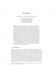
(1) What are the compelling scientific issues for which computation is required? The pedestal is a steep gradient region at the edge of high-confinement plasmas in tokamaks. Edge localized modes (ELMs) are instabilities that periodically remove the pedestal, which can result in large heat load fluctuations on divertor plates. There are basically three compelling issues concerning the pedestal and ELMs in burning plasma experiments: First, it is important to know that a pedestal will form at the edge of the plasma in order to produce the enhanced confinement associated with H-mode plasmas. Second, the height of the pedestal at the edge of the temperature profile has a nearly multiplicative effect on the core temperature profile and, consequently, the confinement and fusion power production depend sensitively on pedestal height. Third, it is important to simulate the heat pulses produced by large ELM crashes, which can damage the plasma-facing components of the divertor. Hence, it is important to predict the size and frequency of ELMs as well as the effect of ELM stabilization techniques that can be used in burning plasma experiments. The steady and transient plasma conditions in the pedestal region have a significant impact on the ability of ITER and follow-on devices to handle power loads, exhaust the helium ash, and fuel the fusion burn.
Figure 2.1: Ions and electrons (large and small dots) from an edge gyrokinetic code simulation. Red and blue background colors represent co and counter-current plasma parallel flow.
(2) What is the current state of the art and what is missing from the current capability? A variety of approximate models have been developed to simulate pedestal formation and ELM cycles within integrated modeling codes. To improve the physics fidelity of the approximate models, first-principles modeling of the edge plasma has been initiated. First-principles gyrokinetic simulations of the pedestal and scrape-off-layer are being developed by the Center for Plasma Edge Simulation (see Fig. 2.1) and the Edge Simulation Laboratory. Neoclassical kinetic transport in edge pedestals has been investigated with spatially axisymmetric gyrokinetic codes. Full 5D electrostatic turbulence simulations are nearing
17
CHAPTER 2. SCIENTIFIC ISSUES completion. In addition 2D and 3D two-fluid codes have been applied to modeling of the pedestal on transport and turbulence timescales. Neutral transport modeling has been developed independently for both kinetic Monte Carlo and fluid formulations, to improve predictivity. ELMs are studied computationally with linear MHD and nonlinear extended MHD codes as well as two-fluid codes. Kinetic effects on ELMs may well play a significant role, but these await the development of electromagnetic versions of the edge kinetic codes for a full understanding. Complete gyrokinetic simulations of pedestal growth and ELM cycles are in the process of being developed.
(3) What new capabilities are needed? Proper simulation of the pedestal requires integration of distinct physics ingredients within the spatial domain of the pedestal as well as coupling to other spatial regions of the plasma. Within the pedestal one must simulate the interaction of the main plasma species, neutrals, impurities, radio frequency sources, and possibly radiation from the plasma. The behavior of the pedestal is also influenced by interactions with material walls and with the core plasma. Also required is multiscale integration between plasma phenomena operating on timescales associated with turbulence, neoclassical physics, large-scale instabilities, various atomic physics processes, and transport. Eventually, most of the other physical phenomena occurring in the core and external controls will need to be integrated in the pedestal simulation, since those phenomena can affect the pedestal growth and ELM behavior. Kinetic neoclassical and electrostatic turbulence simulations and two-fluid MHD simulations can yield insight on unresolved pedestal phenomena. Future advances in the simulation of pedestal and ELMs, however, will require the development of fully electromagnetic edge gyrokinetic simulations for the turbulence and MHD timescales, as well as the integration of physical phenomena noted above. These are difficult long term endeavors, but essential for the success of the fusion program.
2.1.3
Tritium migration and impurity transport
(1) What are the compelling scientific issues for which computation is required? Tritium must be removed from wall deposits for reuse and to avoid site-license limits. The concern is that a substantial amount of tritium will migrate to regions that are inaccessible to known removal techniques. Predicting the distribution of tritium requires understanding plasmaaided migration of the tritium in the divertor and edge plasma regions. A closely related issue is impurity production and transport. There are two ways impurities can degrade fusion gain: (1) dilution of the reacting ions with impurity ions degrades performance; and (2) impurities can radiate energy from the core, thereby cooling the plasma and thus reducing the fusion reaction rate.
18
CHAPTER 2. SCIENTIFIC ISSUES Impurities arise because of plasma contact with material components as well as the generation of helium ash by fusion reactions. The release of material atoms as impurities can be the result of impact from high-energy particles (physical sputtering), chemical reactions involving the surface (chemical sputtering), or even evaporative release if liquids are used. In practice, these processes interact or they can merge into a more complex release mechanism. Understanding and predicting impurity production rates is complicated by the presence of various wall materials in the device (e.g., presently ITER plans to use beryllium, carbon, and tungsten in different locations). Modeling the erosion process is necessary for predicting the final resting place for tritium, since all hydrogenic species will recycle many times from the walls into the plasma.
(2) What is the current state of the art and what is missing from the current capability? The prediction of tritium and impurity content on surfaces and in the plasma can be divided into production and transport processes. The modeling of deuterium and tritium (DT) recycling involves wall material simulations, which are presently performed by simple 1D diffusion codes. For a saturated layer of DT, one D or T particle is released per incident D or T ion, but the yield ratio is not modeled. Present experimental results indicate that D or T penetrates much deeper into the material than simple models predict. The impact of energy pulses from ELMs on both D or T recycling and impurity production is believed to be important, but is included only in highly idealized surface point model time-dependent fluid transport models. The migration mechanism for tritium is believed to be strongly influenced by chemical sputtering, which produces tritiated hydrocarbon molecules that are then dissociated and ionized by the plasma and strike the wall elsewhere in a multi-step process. Such transport is modeled by 3D Monte Carlo ion/neutral codes that use a prescribed deuterium and tritium plasma background. For carbon divertors (an ITER baseline design), tritium migration is controlled by repeated breakup, loss, and re-injection of the hydrocarbons and processes that cause surface transport. The rates for the large number of molecular and surface processes are based on simple physics arguments, which often have a large number of adjustable coefficients to fit complex experimental results. To even approach the tritium migration levels observed in the JET tokamak, the surface rates need to be adjusted to values substantially larger than expected from simple theory. Hence, the tritium build up in JET was much larger than initially anticipated. Coupling of near-surface hydrocarbon models to whole-edge transport is needed. Impurities are released from the wall via physical or chemical sputtering from incident ions and neutrals. The physical sputtering yield is relatively well understood, and details of extensive laboratory data fit well with binary-collision-approximation codes. On the other hand, chemical sputtering is not well understood, and it is believed often to be dominant in fusion devices using carbon materials. Values of the chemical sputtering yield typically rely on empirically parameterized models, which utilize experimental data on material composition, surface conditions, wall temperature, incident plasma flux, and sometimes long-time exposure history. Threedimensional molecular dynamic simulations are beginning to provide information on chemical sputtering. Extensions of the molecular dynamic sputtering database, mixed material simulations, and kinetic Monte Carlo simulations are needed.
19
CHAPTER 2. SCIENTIFIC ISSUES Transport of the higher-Z impurities (for carbon, after the molecular breakup) in the edge plasma is presently modeled by 2D time-dependent fluid codes including classical collisional transport and phenomenological cross-field diffusion to represent turbulent transport. Also, 3D steady-state Monte Carlo impurity ion transport simulations have been carried out, but without self-consistent coupling to the deuterium and tritium plasma. Short-time turbulence simulations with one impurity component indicate that inward transport of impurities from near the wall can substantially exceed the impurity diffusion rates assumed in designing ITER. Future models need to include the impact of 3D turbulence on multi-species impurities and coupling to kinetic transport.
(3) What new capabilities are needed? Improved models and effective integration of the results into whole-device simulations will allow identification of discharge scenarios that would lead to excessive tritium retention and/or impurity-limited operation. Such a tool can also be used to test ideas for tritium and impurity mitigation techniques. Models for tritium retention within the first few microns of wall materials need to be based on time-dependent diffusion simulations, extended to 2D and perhaps 3D, and must be coupled to edge transport codes. Inter-atomic potentials need to be developed for ITER mixed materials, and these potentials must be used in 3D molecular dynamics simulations of sputtering. The molecular dynamics results should be supplemented by 2D kinetic Monte Carlo simulations of slower surface chemistry processes that also generate hydrocarbons. These results need to be parameterized in multi-variable tables that can be used in long-timescale transport simulations. Results from near-surface hydrocarbon plasma/neutral codes should be coupled (or parameterized) to full edge transport codes. Multi-species, 2D, two-velocity kinetic ion transport codes need to evaluate collisional, neoclassical impurity transport in the edge region, and coupled to the core. Multi-species, 3D fluid and 3D two-velocity kinetic ion turbulence simulations should calculate the transport of impurity ions in the edge with strong turbulence present. These impurity transport models should then be coupled to the core transport code.
2.1.4
Performance optimization and scenario modeling
(1) What are the compelling scientific issues for which computation is required? Optimizing the performance of burning plasma discharges requires accurate computations of the temperature and density profiles, the distribution of energetic particles, and the concentration of impurities. Scenario modeling, which involves predicting the evolution and control of plasma profiles and abrupt events in a tokamak discharge, is a critically important issue for ITER. Since each ITER discharge will cost roughly a million dollars, there must be careful scenario modeling and planning before new discharges are carried out in the real device. Since no more than a few hundred disruptions can be allowed at full current in ITER, scenario modeling must be used to predict and avoid the conditions that are likely to produce disruptions. Scenario 20
CHAPTER 2. SCIENTIFIC ISSUES
Figure 2.2: Illustration of the interacting physical processes within a tokamak discharge modeling must be used to set up the input and actuator settings that are required to optimize the performance of each ITER discharge. Since multiple experimental teams will be competing for running time on ITER, the teams with the best scenario modeling are likely to get the most running time. Scenario modeling can be used to explore new and unusual discharge conditions before those discharges are tried in the real experiment. Once an ITER discharge is completed, scenario modeling will play an essential role in understanding the interacting physical processes that are observed within that discharge. The results of scenario modeling will be compared with experimental data in order to validate the available models for physical processes and to determine which models need to be improved. Validated simulations provide a way to embody the knowledge of fusion plasmas. (2) What is the current state of the art and what is missing from the current capability? The computation needed for optimization of burning plasma experiments involves the selfconsistent combination of many physical processes including transport as well as sources and sinks of heat, momentum and current; the distribution of energetic particles; fuelling and impurities; plasma edge conditions; and the effects of large-scale instabilities (see Fig. 2.2). Most of the large, full-featured integrated modeling codes were started about 30 years ago and they consist of a patchwork of contributions from a large number of people who were often working on isolated tasks under time pressure. The required models are often scattered among a variety of codes and are not consistent in their level of sophistication. Most of the codes are not modular, they do not use modern software engineering methods, and the programming practices do not 21
CHAPTER 2. SCIENTIFIC ISSUES always conform to accepted standards for reliability, efficiency, and documentation. As a result, these codes are difficult to learn to run correctly and difficult to maintain. (3) What new capabilities are needed? A comprehensive whole-device integrated modeling code framework is needed for scenario modeling. The framework must allow for the computation of time-dependent profiles of sources, sinks and transport of heat, momentum, charged thermal and energetic particles, neutrals, and plasma current. The framework must have options to use modules for neutral beam injection, radio frequency heating and current drive, nuclear reactions, atomic physics, Ohmic heating, equipartition, as well as transport driven by neoclassical processes and turbulence. The framework must also include models for the structure and consequences of large-scale instabilities, models for predicting conditions at the plasma edge, and models for the interactions between the plasma and the rest of the tokamak. Finally, the framework should include synthetic diagnostics and the tools needed to make quantitative comparisons between simulation results and experimental data. Simulations can make a substantial contribution in a way that traditional theory and experiment, by themselves, cannot. The integrated modeling framework must allow for tight coupling between many of the interacting physical processes. Different kinds of large-scale instabilities, for example, can interact with each other and can strongly modify plasma profiles which, in turn, can affect the driving mechanisms producing instabilities. In particular, sawtooth oscillations redistribute current density, thermal particles and fast particle species. The helical structures produced during sawtooth crashes can seed neoclassical tearing modes. Neoclassical tearing modes are very sensitive to current and pressure profiles and they produce flat spots in those profiles. In addition, boundary conditions at the edge of the plasma strongly affect core plasma profiles. Since anomalous transport is stiff (i.e., increases rapidly with increasing temperature gradient), the core temperature profile is strongly affected by the height of the pedestal at the edge of the plasma and by wall conditioning. The interactions between many of the physical processes are indicated in Table 2.1, at the end of this chapter, where the phenomena or plasma properties, indicated in the rows, are controlled or affected by the physical processes listed in the columns.
2.1.5
Plasma feedback control
(1) What are the compelling scientific issues for which computation is required? The burning plasma regime is fundamentally new, with stronger self-coupling and weaker external control than ever before. Since burning plasma experiments are designed to operate near parameter limits, there is a particularly critical need for plasma feedback control in order to avoid disruptions and optimize performance. Large-scale instabilities that can lead to disruptions are controlled by the use of modulated heating and current drive. Edge localized modes can be controlled by the application of non-axisymmetric magnetic fields.
22
CHAPTER 2. SCIENTIFIC ISSUES Owing to its role as the first burning plasma experiment, its nuclear mission, and its stringent licensing requirements, at the time of its commissioning, ITER will be the most controldemanding tokamak ever built. The uncertainties associated with self-heated plasmas coupled with the need to certify high confidence control performance will place extreme demands on the physics simulation community and will require an unprecedented amount of integration between frontier physics understanding and mission-critical control solutions.
(2) What is the current state of the art and what is missing from the current capability? Computational tools currently available to support the design of ITER feedback control include several 1.5D axisymmetric resistive MHD (Grad-Hogan) codes with various ITER-relevant actuator modules. In addition, there are suites of design codes in use by experimental teams at various laboratories. There are many codes that model specific physics elements used for control, but these codes typically involve minimal integration with other physical effects. The large collection of modeling codes used in the U.S. have widely varying levels of accuracy, completeness, and validation, which are often insufficient for ITER requirements. The highly specialized design codes are not easily modified to include more than one physics phenomenon and are not extensible to the next generation of fusion devices. Control simulations that can flexibly integrate effects of different physics modules have been developed, but lack an extensive library of validated modules. The connection between these simulations and real-time control platforms has been demonstrate and used routinely on some devices. However, the connection capability required for ITER has not been developed.
(3) What new capabilities are needed? The FSP can supply three elements critically required by ITER in the area of control: (1) Control design models derivable from more detailed physics models; (2) full or partial shot integrated control scenario simulation capability; and (3) a modular infrastructure for flexibly using these products. The ITER CODAC (Control Data Access and Communications system) presently specifies an integrated capability to perform control designs for every sensor-plantactuator loop, a system to verify implementation of control algorithms, and a system to confirm performance of these algorithms against simulated tokamak function. Although these functions necessarily require “whole-device modeling,” in practice it is essential to be able to emphasize or de-emphasize a subset of control loops in order to focus on key systems under development or test. The high level of confidence required for control of ITER means that all of the modules produced by the FSP and used in this particular mission must be extensively validated, and the ability to validate against operating devices constantly and routinely must be built into the architecture. Fig. 2.3 illustrates the key elements of integrated plasma control as applied in several currently operating tokamaks and envisioned for ITER. FSP provides an optimal path to supply the modeling, simulation, validation, and control verification elements required by ITER in this approach to model-based, high confidence design.
23
CHAPTER 2. SCIENTIFIC ISSUES
Figure 2.3: Schematic of integrated plasma control process, the systematic design approach that will be followed by ITER. The modeling, system simulation, and validation functions critically require FSP tools to enable the high confidence design and verification planned for ITER controllers. (Note: PCS denotes “Plasma Control System,” representing the real-time computer control system). Many ITER control solutions will require full Grad-Hogan solver simulations (preferably in the form of several available kernels) with relevant coupled core and boundary physics, coupled divertor physics, actuator effects modules (heating, current drive, rotation, fuelling), and diagnostic signal generation modules. Models describing the coupled particle control loops (including plasma ions and impurities, wall sources, divertor pumping) will be essential for operating point and burn control. Specific modules for non-axisymmetric instabilities will be required, but it will be essential to provide both detailed physics models and “reduced” or control-level models derivable from the detailed models. Even when using such control-level models, often consisting of simpler representations of relevant physics, the long timescale of control simulations will demand the use of multiprocessor, large-scale computing to facilitate iterative control design and testing. Eventually, ITER procedures will demand that many of these simulations be run within a day of operational use, or even between shots.
2.2
Physics Components Essential for Integrated Burning Plasma Simulations
Many physics components are needed to address critical issues in the integrated modeling of burning plasma experiments. In this section, examples of physical processes are described that 24
CHAPTER 2. SCIENTIFIC ISSUES affect the optimization of burning plasma performance: Core and edge turbulence and transport; large-scale instabilities; sources of heat, momentum, current and particles; and energetic particle effects. Other physics components include edge physics (see Subsection 2.1.2), equilibrium, and atomic physics.
2.2.1
Core and edge turbulence and transport
(1) What are the compelling scientific issues for which computation is required? Fairly comprehensive gyrokinetic codes for the core plasma now exist to compute turbulence and transport (see Fig. 2.4). There are still unresolved problems in computing electron thermal transport and computing the effects of zonal flows and magnetic shear for all of the modes of turbulence. One specific example of the current limitations of turbulence modeling is the simulation of electron-gradient-drive turbulence where the electron gyro-radius scale is important, which requires resolving the electron scale as well as the ion scale. This requires a factor of 40 reduction in the time step and the grid cell size in the directions perpendicular to the equilibrium magnetic field, resulting in a factor of (40)3 increase in required computing power. Another unresolved problem is related to the importance of linking turbulence, which is computed using gyrokinetic codes on microsecond timescales, with transport, which determines plasma confinement on much longer timescales. There are a number of key scientific issues for the edge plasma that require turbulence and transport computations. These include: (1) The structure of the edge pedestal, which (as noted earlier) has a strong impact on core confinement and hence overall fusion performance; (2) the ability of the edge plasma to adequately disperse the power and particle exhaust from the core plasma, both on the average and in response to transient events (ELMs and blobs); and (3) the inflow of neutral gas and impurities from walls, which establishes the particle fueling and impurity concentration for the core plasma. Turbulence simulations are more difficult at the plasma edge than in the core region. The increased difficulty is due to the steep plasma gradient at the edge, which affects the lowest order particle kinetics, the nonlinear turbulence kinetics coupling between core and edge, and the coexistence of nested and open magnetic surfaces at the plasma edge.
(2) What is the current state of the art and what is missing from the current capability? In the area of gyrokinetic simulation of plasma turbulence there are two classes of algorithms — continuum and particle-in-cell. These codes typically use a pseudo-spectral representation in the toroidal direction and field-line following coordinates in general axisymmetric magnetic equilibrium. The plasma domain is typically an annulus, which can include either the whole torus or a periodic wedge. The continuum approach follows the characteristic of the gyrokinetic equation back in time one timestep and then uses a spline fit to evaluate the perturbed distribution function at the location of the characteristic at the earlier time. The continuum algorithm requires a five-dimensional grid. The particle-in-cell approach follows characteristics 25
CHAPTER 2. SCIENTIFIC ISSUES of the perturbed distribution function on a three-dimensional grid. The gyrokinetic codes scale extremely well using thousands of processors (or cores) on the most powerful contemporary high performance computers, typically achieving 12 to 15% of the peak FLOP rate. With regard to transport models, at the present time, simulations using different transport models yield different predictions for ITER performance even though simulation results using the different transport models match experimental observables of tokamak data about equally well. Core gyrokinetic codes cannot be applied to the edge plasma for a variety of reasons, including the presence of steep gradients in the pedestal region (on scales overlapping with particle orbit widths), the geometrical complexity resulting from the presence of closed and open magnetic surfaces, the more complicated plasma equilibrium in this region, which includes explicitly at least two-dimensional variations, the proximity to a highly conducting wall, and the importance of impurity and neutral-particle dynamics in this region. In addition, the gyrokinetic formalism itself requires modification for the edge. While fairly mature fluid turbulence and transport codes exist for this region, truly quantitative predictive simulation requires gyrokinetic codes, and these (along with the necessary formalism) have only recently begun to be developed. Figure 2.4: Turbulence from a gyrokinetic simulation. The triggering of edge localized modes (ELMs) is typically predicted by linear MHD codes. The subsequent evolution of an edge localized mode is presently modeled using extended nonlinear 3D MHD codes, which include some two-fluid effects, and by fluid turbulence codes with electromagnetic effects as noted in Subsection 2.1.2. These modes straddle the parameter regime between long wavelength MHD and short wavelength turbulence. Although these modes are centered near the plasma edge, they have strong impact on the wall and well into the core.
(3) What new capabilities are needed? Advances in core gyrokinetic codes are required in order to carry out simulations that span the range of turbulent wavelengths from the electron gyro-radius to the ion gyro-radius with full electromagnetic capability. Edge gyrokinetic codes must be developed to a level of maturity comparable with the core turbulence codes. In addition, long-timescale edge gyrokinetic codes, capable of evolving the plasma equilibrium, must be developed with capability comparable to today’s mature edge fluid transport codes. Gyrokinetic codes must be developed to investigate
26
CHAPTER 2. SCIENTIFIC ISSUES turbulence in three-dimensional plasma equilibria, such as regions with magnetic islands or the open flux surface regions in the scrape-off-layer at the edge of the plasma. Additionally, the capability must be developed to launch a gyrokinetic simulation using local parameters produced by integrated modeling simulations. Comprehensive reduced transport models must be developed using these advanced gyrokinetic capabilities. Models for all of the channels of transport are needed with sufficient physics fidelity to simulate internal transport barriers. ELM models must extend over a larger wavelength range than in current codes in order to resolve nonlinear interactions adequately. ELM simulations are being developed to extend to small wavelengths, including gyrokinetic effects, in order to reproduce the observed filamentation in the scrape-off layer. ELM models need to be developed in order to simulate the complete ELM crash routinely with the nonlinear transport of energy, momentum, particles, and the associated plasma current. Also, models for the various types of ELMs must be developed.
2.2.2
Large-scale instabilities
(1) What are the compelling scientific issues for which computation is required? Large-scale or macroscopic instabilities limit plasma performance in all magnetic confinement devices. In tokamaks, sawtooth oscillations (and more generally m = 1 instabilities shown in Fig. 2.5), conventional and neoclassical tearing modes, ideal MHD pressure- and current-driven instabilities and resistive wall modes restrict operational regimes and lead to confinement degradation and disruptions. For ITER and beyond, it is crucial that predictive understanding of the nonlinear dynamics of these instabilities be used to develop tools for instability avoidance, suppression, and mitigation. While linear MHD provides an excellent predictive capability for ideal instability onset, nearly Figure 2.5: Kink instability from a nonlinear extended all of the forefront research in macro- MHD simulation. scopic instability modeling involves nonlinear mode evolution using extended MHD models. Extended MHD includes physics relevant to long mean free path plasmas where kinetic and neoclassical processes are of central importance for predicting the complete evolution of large-scale instabilities.
27
CHAPTER 2. SCIENTIFIC ISSUES (2) What is the current state of the art and what is missing from the current capability? The ideal and resistive MHD descriptions of large-scale instabilities have matured from many decades of theory and computation. State-of-the-art extended MHD models and codes are now able to incorporate the effect of energetic ions on ideal and resistive m = 1 modes via a hybrid model of resistive MHD and gyrokinetic energetic ions. These models include two-fluid effects such as Hall physics and the electron pressure in magnetic reconnection that governs how fast magnetic islands can be formed in a nearly collisionless plasma. Simulations using these effects produce a qualitative description of neoclassical tearing mode onset and evolution using approximate neoclassical closures. Simulations are also used to follow resistive wall mode evolution using ideal and resistive MHD models in realistic geometries. In order to describe the nonlinear properties of macroscopic instabilities accurately in toroidal confinement devices, it is necessary to include physical effects beyond resistive MHD, such as the self-consistent interaction of MHD modes with energetic particles and plasma flows. The extended MHD model, as it is currently formulated, has a glaring deficiency in its lack of a rigorous closure on higher-order moments, namely the stress tensor and heat flux, for a long mean free path fusion plasma. The extended MHD model must include neoclassical closures in the parallel electron equation (Ohms law) to introduce neoclassical tearing mode effects, neoclassical ion flow damping (poloidal and toroidal in the presence of 3D magnetic perturbations), two-fluid physics and self-consistent gyroviscous forces. As MHD instabilities evolve, they directly affect global profile evolution and energetic particle confinement, which can provide the precursor behavior for plasma disruptions. In order to control and suppress large-scale instabilities at the highest possible beta, the critical physics must be understood near the marginal stability boundary, where the large-scale instability critically depends on subtle physics inside the narrow layers at low order rational magnetic surfaces. The need to resolve the narrow layer physics also brings daunting challenges to numerical algorithms.
(3) What new capabilities are needed? Breakthroughs must be made in three areas to achieve predictive understanding of largescale instability and hence facilitate their avoidance, suppression, and mitigation of damaging instabilities in ITER and even more so in DEMO. The first area involves a first-principles-based formulation of a moment closure for long mean free path fusion plasmas that can be numerically implemented and an integrated long mean free path extended MHD and gyrokinetic microturbulence model that can be implemented either in closed coupling form or using multiscale coupling methods. The second area involves meeting the computational challenges of implementing the integrated physics models that cut across the traditional topical areas in fusion plasma physics. Specifically one has to devise a code framework that concurrently solves the fluid-moment-based extended MHD equations, the drift kinetic equation for long mean free path moment closure, and the gyrokinetic equation for micro-turbulence (potentially only locally at narrow layers where it 28
CHAPTER 2. SCIENTIFIC ISSUES is necessary). This task could require judicious use of multiscale methods to take advantage of the scale separation where it appears. The third area involves numerical algorithms, particularly on scalable solvers for implicit time advancement for strongly hyperbolic partial differential equations such as the extended MHD equations. Such a scalable solver should be compatible with an aggressive grid adaptation scheme that concentrates grid resolution near the location of dynamically moving narrow layers.
2.2.3
Sources and sinks of heat, momentum, current and particles
(1) What are the compelling scientific issues for which computation is required? Radio-frequency power is being considered in the ITER device for applications that include core heating of the plasma as well as localized control of the pressure and current profiles in order to access regimes with high energy confinement time and bootstrap current fraction. In order to ensure that these applications are successful, it is necessary to have a simulation capability for predicting how much power can be coupled to the plasma. This requires treatment of both linear and nonlinear processes such as surface wave excitation, RF sheath formation and parametric decay instability. These problems are further exacerbated in ITER by the fact that the antenna launching structures for long wavelength RF power will be located far from the plasma edge. Once RF power has been coupled to the core, there is a need to simulate how the electromagnetic waves will interact with energetic ions. Other sources include neutral beam injection, nuclear fusion reactions, and neutrals from the plasma-facing walls. The models for neutral beam injection must be extended to apply to the new high energy neutral sources that will be used for adequate beam penetration in ITER. For the key issues, model status, and needs related to the retention of tritium and impurity wall sources, the reader is referred to Subsection 2.1.3
(2) What is the current state of the art and what is missing from the current capability? Boundary conditions for RF sheath formation and dissipation have been derived for the near- and far-field sheath problems, in both 1D and 2D, but have not yet been incorporated selfconsistently into full-wave electromagnetic field solvers. Taking advantage of large-scale parallel computing resources has already made it possible to assemble linear antenna coupling models consisting of full-wave field solvers and 3D electromagnetic antenna codes, but only for a single mode excited by the RF launcher (see Fig. 2.6). Also, bounce-averaged, zero banana-width Fokker-Planck codes have been coupled to full-wave solvers that employ a plasma response developed in either the finite ion gyro-radius limit or for arbitrary perpendicular wavelength relative to the ion gyro-radius. These coupled models also use the plasma response due to the full nonthermal ion and electron distribution functions, but do not include finite ion orbit effects in the Fokker-Planck physics. Currently, the computation of electron cyclotron current drive (ECCD) sources is performed using bounce-averaged Fokker-Planck codes coupled to toroidal
29
CHAPTER 2. SCIENTIFIC ISSUES
Figure 2.6: Three-dimensional ICRF wave fields in the NSTX spherical tokamak (left panel) and in ITER (right panel). ray tracing descriptions of the electron cyclotron wave propagation. These simulations have not yet been used to compute suppression of instabilities because of the lack of coupling to extended MHD simulations of the plasma. A Monte Carlo technique is most widely used to model the slowing down of energetic particles produced by neutral beam injection and fusion reactions. The module implementing this technique includes multiple beam-lines, beam-line geometry, and beam composition by isotope and energy fraction. After deposition of fast ions in the plasma by atomic processes, the modeling of the slowing down includes anomalous diffusion of fast ions, the effects of large-scale instabilities, the effects of magnetic ripple, and the effects of finite Larmor radius. The software computes the trajectory of neutral atoms and fast ion orbits as they slow down in the thermal target plasma, including the effects of charge exchange losses and the recapture of fast ions. The main limiting approximations in the current software are that it is assumed that the Larmor radius is small relative to plasma size, that fast ions do not interact with each other, and that the background plasma is axisymmetric. It is assumed in the collision operator that the beam energy is much larger than the background plasma thermal energy. Also, there is no model for the scrape-off-layer so it is assumed that fast ions are lost once they leave the core plasma.
(3) What new capabilities are needed? Further utilization of terascale and petascale computing platforms should make it possible to advance the state-of-the-art significantly. First, the linear coupling analysis using a full-wave solver and antenna code should be carried out using the full toroidal antenna spectrum of an
30
CHAPTER 2. SCIENTIFIC ISSUES RF launcher. Second, nonlinear formation of near and far-field RF sheaths should be addressed self-consistently by implementing metal wall boundary conditions for the sheaths in ICRF fullwave solvers. The full-wave solvers should also be modified to solve numerically the three-wave coupling problem of a pump wave decaying into daughter waves that damp in the plasma edge. Self-consistent coupling of Monte Carlo orbit codes to ICRF full-wave solvers to account for finite ion orbit effects should also be carried out. The improved modules for sources and sinks of heat, momentum and particles coupled with the modules in an integrated modeling code (including those for turbulence and transport, largescale instabilities, energetic ions, etc.) are required to obtain a physically correct description of the evolution of burning plasmas. Neutral beam and fusion heating modules must be developed for three-dimensional plasmas, including the effects of magnetic islands, regions of stochastic magnetic field, magnetic ripple, and the scrape-off-layer. The modules must include more accurate atomic physics cross sections and extensions of the charged-particle collision operators.
2.2.4
Energetic particle effects
(1) What are the compelling scientific issues for which computation is required? Fusion reactions and auxiliary heating produce energetic particles, which are expected to dominate the behavior of burning plasma experiments such as ITER. Energetic particles can drive large-scale instabilities, such as the Toroidal Alfv´en Eigenmodes, and the energetic particles can interact strongly with large-scale instabilities, which can eject the particles before they have had a chance to slow down to heat the background plasma. Additionally, prompt loss of energetic ions may be an issue in ITER because they can seriously damage reactor walls. An important new topic in burning plasmas is the nonlinear interaction between the energetic particle component and the bulk thermal background plasma. Integrated simulations are required to determine if neutral beams can be used in ITER to drive sufficient plasma rotation for stabilizing resistive wall modes and to drive the plasma current, which is important for advanced operating scenarios. Other scientific issues that require computation result from the following: Alfv´en instabilities can broaden the beam ion distribution and influence the profile of beam-driven current and toroidal rotation. The energetic particle-driven Alfv´en instabilities can induce zonal flows, which can suppress core plasma turbulence. Energetic particles can have a significant impact on MHD modes. In ITER, fusion alpha particles can stabilize the internal kink mode leading to monster sawteeth and can also stabilize resistive wall modes. Finally, thermal plasma turbulence could also induce significant energetic particle transport.
(2) What is the current state of the art and what is missing from the current capability? At present, the state-of-the-art kinetic/MHD hybrid codes can routinely simulate one cycle of growth, saturation, and decay of energetic particle-driven Alfv´en modes for moderate toroidal mode numbers (e.g., toroidal harmonic, n, up to 5) for parameters of present tokamak 31
CHAPTER 2. SCIENTIFIC ISSUES experiments. The codes are limited in comprehensive physics and numerical efficiency for selfconsistent high-resolution simulations of high-n modes in burning plasmas. For example, the state-of-the-art codes often have less than complete linear stability physics and the codes are not sufficiently efficient to be used effectively for high-resolution long-time simulations.
(3) What new capabilities are needed? For ITER, an important goal is to determine if Alfv´en instabilities can greatly affect fast ion transport, including alpha particles and neutral beam ions, and what the impact of alpha particle-driven instabilities might be on background plasmas. To accomplish this goal, selfconsistent nonlinear simulations of energetic particle-driven modes are needed on transport timescales, including accurate sources and sinks. This requires significant upgrades of existing codes and/or building new codes capable of efficient massively parallel calculations using the most powerful high-performance computers available. There is a need to investigate fast ion transport, driven by interactions of the energetic particles with Alfv´en instabilities with high mode number. A reasonable estimate of what is needed is about a factor of ten higher resolution (in each dimension) and a factor of ten longer physical time period for a self-consistent integrated simulation of alpha particle-driven Alfv´en instabilities. It is expected that this goal of simulation of energetic particle modes can be achieved within five years. Attaining this goal is possible because: (1) Peak computing capability will be increased from platforms currently available for fusion simulations to the petascale, which is a factor of 100 increase and (2) the state-of-the-art hybrid codes can be made more efficient by using advanced numerical algorithms including high-order spectral elements and fully implicit numerical schemes.
32
CHAPTER 2. SCIENTIFIC ISSUES
Table 2.1: Interactions of Physical Processes in Tokamaks Prediction and Control
Sources and Actuators (RF, NBI, fueling, coils)
Extended MHD and Instability Models
Transport and Turbulence
Energetic Particles
Edge Physics
PlasmaWall Interactions
Pressure profile
Source of heat and particles affects pressure profile
Magnetic islands locally flatten pressure profile. Ideal no-wall beta-limit affected by pressure profile
Pressure profile determined by transport, together with sources and sinks
Co-resonant absorption with RF power deposition broadening by radial diffusion of fast particles
Boundary conditions affect pressure profile. RF power losses in edge due to nonlinear processes
Neutrals from wall affect density profile. RF power loss in vessel due to sheaths
Current profile
Noninductive currents; q-profile control
Stability determined by, and magnetic islands locally flatten, current density profile
Magnetic diffusion equation used to compute current profile
Current profile broadening due to radial diffusion of fast electrons
ELM crashes periodically remove edge current density
Eddy currents in wall affect plasma current profile
Plasma shaping
Controllability of plasma shape and divertor
Controllability of ELMs and beta limit affected by plasma shape
Transport affects profiles that affect core plasma shaping
Profile of energetic particle pressure affects core plasma shaping
Shape at plasma edge affects core plasma shape
Coil currents and wall eddy currents affect plasma shape
Energetic particle profile
Co-resonant RF interactions modify velocityspace distribution
Effects of NTM on energetic particle profile
Effects of core turbulence on energetic particle profiles
33
CHAPTER 2. SCIENTIFIC ISSUES Table 2.1: Interactions of Physical Processes in Tokamaks Prediction and Control
Sources and Actuators (RF, NBI, fueling, coils)
Neutrals
Gas puffing, wall recycling and NBI affect neutrals profile
Extended MHD and Instability Models
Transport and Turbulence
Energetic Particles
Edge Physics
PlasmaWall Interactions
Neutrals charge exchange with energetic particles
Influx of neutrals strongly affects pedestal density formation
Neutrals recycle at first wall
Neoclassical ECCD, Tearing LHCD for Modes stabilization, rotation control
Bootstrap current model, threshold, intrinsic rotation, island seeding by sawtooth crashes
Anisotropic transport on onset threshold and saturation, effect on neoclassical polarization currents
Alpha loss due to magnetic island and stochastic; energetic particle effects on NTM
Helical B (via poloidal coupling with NTM) on pedestal
Remnant alphas
Resistive Wall Modes
Rotation, physics of the rotation stabilization; controllability with nonaxisymmetric coils
Beta limit, intrinsic rotation, error field locking, error field amplification; RWM triggering by ELM
Rotation damping, nature of anomalous viscosity
Energetic particle beta on stability
Finite pressure and current in the edge need to be accounted for, helical B on pedestal
Disruption mitigation, currents in the SOL
m=1 helical instability
q(0) and rotation control
Instability onset, fast reconnection, saturation amplitude, global q evolution, NTM seed
Impact of topology on turbulence and back reaction on m=1
Alpha stabilization, monster sawteeth, fishbones, alpha loss and redistribution
Impact of transient heat, particle, alpha’s and helical B on pedestal transport and stability
Load to the wall and impurity production
34
CHAPTER 2. SCIENTIFIC ISSUES Table 2.1: Interactions of Physical Processes in Tokamaks Prediction and Control
Sources and Actuators (RF, NBI, fueling, coils)
Extended MHD and Instability Models
Transport and Turbulence
Energetic Particles
Edge Physics
PlasmaWall Interactions
Rotation and Flow Shear
RF/NBI are primary sources
Neoclassical transportinduced intrinsic rotation, error field damping, MHD continuum damping
Momentum transport and selfgenerated zonal flow
Rotation damping, NBI-induced toroidal rotation in the presence of Alfv´en modes and MHD modes
Selfgenerated radial electric field in pedestal
Boundary conditions at first wall and tokamak structure
Pedestal
Localized heating and current drive
Pedestal bootstrap current
L/H transition, connection to core, pedestal electron and ion transport, shear flow generation and sustenance
Energetic particle and ash transport; effects of energetic particle redistribution on pedestal
L/H transition
Impurity flux
Edge Localized Modes (ELMS)
Localized CF, ELM affects ICRF and LHRF coupling; suppression of ELMs: RMP, pellet, shaping
Ballooningpeeling, bootstrap current, intrinsic and induced rotation, interaction with m = 1, NTM, RWM
Connection to core non-diffusive transport, self organized criticallity avalanches, inward impurity transport
Poloidal coupling to AE, induced transient alpha loss
Relaxation events, control by helical B, impurity and ash transport, interaction with pedestal zonal flow
Heat, particle, ash to wall, impurity and transport, radiation coupling
Internal Transport Barriers (ITBs)
ICRF and ECCD — local shear control for triggering and controlling ITB
Minimum q profile manipulation, island as ITB trigger, intrinsic rotation
Formation threshold and structure, all transport channels
Energetic particle interaction with ITB in the presence of Alfv´en modes
Correlation between ITB and pedestal structure
35
CHAPTER 2. SCIENTIFIC ISSUES Table 2.1: Interactions of Physical Processes in Tokamaks Prediction and Control
Sources and Actuators (RF, NBI, fueling, coils)
Extended MHD and Instability Models
Transport and Turbulence
Field Error Penetration
Rotation control
NTV, layer physics, resistive wall mode, suppression of ELMs
Nature of viscosity in resistive layer
Disruptions Efficiency of mitigation by impurity injection; use of other actuators
Halo currents, runaway electrons; reconnection and impurity transport
Thermal / current quench; impurity transport
Runaway electron production and confinement
Wall Flux Out and Impurity Flux in
RF sheathinduced erosion
Sawtooth, NTM, RWM induced transient heat, particle, and alpha pulse
Nature of particle and impurity transport in the core
Alfv´en Eigenmodes, cascade, fishbone, EF-induced EP, and its loss
Transport channels throughout pedestal, ELMinduced transport pulse, helical field-induced transport
Plasma/ materials interaction, SOL connection to pedestal
Discharge scenario
Full discharge controllability; burn control
Role of NTM in hybrid scenario; NTM control; effects of ELM control on scenario
Full discharge achievability and performance prediction
Alphaheated discharge prediction; burn control
Heat and particle flux due to 2nd X-point; divertor control
Wall equilibration effects
36
Energetic Particles
Edge Physics
PlasmaWall Interactions
Mitigation techniques (gas jet, pellets, etc.)
Chapter 3
Verification and Validation Integral to the predictive requirements of the Fusion Simulation Program is a vigorous program to assess the degree to which the codes accurately represent the behavior of the underlying plasma systems that they model. A verification and validation (V&V) program is essential to the role envisioned for FSP. For example, to be useful for modeling prospective scenarios and avoiding deleterious regimes in ITER, the code and device operators must have confidence that the codes are sufficiently accurate in their predictions. Further, it is noted that the ability to predict is related intimately to the scientific process. Predicting the results of experiments that have not yet been carried out is viewed as the strongest demonstration that some significant level of understanding of a physical phenomenon has been achieved. Consequently, codes can be trusted to embody the scientific knowledge gained from research only if they have been thoroughly tested. Current approaches to V&V in simulations of magnetically confined fusion plasmas are often informal and ad hoc. The advent of the FSP provides an opportunity to introduce more uniform and rigorous verification and validation practices, which will establish the fidelity of the advanced physics modules. Verification assesses the degree to which a code correctly implements the chosen physical model, and is essentially a mathematical problem. Sources of error include, for example, algorithms, numerics, spatial or temporal gridding, coding errors, language or compiler bugs, and convergence difficulties. In the case of coupled multiphysics simulations, additional complications arise from the requirement that the numerical methods, used to solve physics in the various code components, are properly matched to ensure a stable and accurate solution. Validation assesses the degree to which a code describes the real world. Simulations are imperfect models for physical reality, which can be trusted only so far as they demonstrate agreement, without bias, with experimental results. Validation is an open-ended physical problem, testing the correctness and completeness of the physical model along with the assumptions and simplifications required for solution.
37
CHAPTER 3. VERIFICATION AND VALIDATION Verification and validation are confidence building exercises. They should be based on wellestablished scientific approaches that allow a priori or a posteriori estimates of the calculational uncertainties, both for cases that are well known (e.g., where trusted experimental coverage exists) and for cases that are less well known. A serious approach to verification and validation requires that tests, once performed, are well documented and archived. Regression suites, a collection of verification test cases with well understood inputs and outputs, should be run regularly (perhaps nightly) to test whether given aspects of verification (e.g., accuracy, spectral radius etc.) continue to be satisfied as a code is developed. As new algorithms are added, the developer designs a verification test and adds this test to the suite. For validation tests, documentation should include data from both the simulation and experiment along with descriptions of data reduction techniques and error analysis.
3.1 3.1.1
Verification Code verification
Code verification includes activities that are related to software quality assurance practices and to finding and removing deficiencies in numerical algorithms used to solve partial differential equations, integral equations, or particle dynamics. Software quality assurance procedures are needed during software development and modification, as well as during production computing. In many areas of simulation, software quality assurance procedures are well developed, but improvement is needed across the board with regard to software operating on massively parallel computer systems. Numerical algorithm verification addresses the software reliability for the implementation of all the numerical algorithms that affect the numerical accuracy of solutions produced by the code. Numerical algorithm verification is conducted by comparing computational solutions with benchmark solutions: analytical solutions, manufactured solutions, and heroically resolved numerical solutions. Improvements in numerical algorithm verification methods and tools are needed in the following areas: • Development and formal compilation of accurate benchmarks are needed in each of the physics components of FSP. These benchmarks will, by necessity, include a variety of analytical solutions, manufactured solutions, and highly accurate numerical solutions. New benchmarks are particularly needed in multiphysics modeling to assess the code correctness and numerical algorithm reliability for these types of models. • To prepare for use with “manufactured solutions,” existing and future computer codes (both government laboratory-developed and commercial software) need to be able to accommodate the addition of source terms in the partial differential equations. That is, the capability must exist to add analytical terms to the right-hand side of the physics-model partial differential equations that are included in the code.
38
CHAPTER 3. VERIFICATION AND VALIDATION • For calibration of production-scale simulations against heroically accurate computational solutions in which the discretization error has been driven well below other possible errors, ultrascale computing resources are required, and the corresponding simulation codes must be able to scale to the limits of these resources.
3.1.2
Solution verification
Solution verification, also referred to as numerical error estimation, deals with the quantitative estimation of the numerical accuracy obtained when partial differential equations, or other continuum-based models, are solved using discretization methods. The primary goal in solution verification is the estimation of the numerical accuracy of all of the solution quantities of interest in a given simulation. Solution verification is related to the topic of adaptive mesh refinement. However, the goals of adaptive mesh refinement are more restrictive than those of solution verification. The discretization errors must be quantified so that these errors can be separated, in principle, from other error and uncertainty sources, such as physics modeling errors and variabilities in physical properties. The primary shortcomings in present methods are: (a) The computational expense of estimating discretization errors using solutions on multiple mesh resolutions and (b) the lack of robustness of existing methods in complex physics simulations. Improved solution verification methods are needed in the following areas: • Improvement and extension of existing recovery methods and residual-based, or adjoint, methods are required for unsteady (parabolic) and hyperbolic problems. Existing methods have been developed only for very restricted physics applications for elliptic partial differential equations. A need exists for extending these methods to engineering quantities of interest, to multiphysics simulations, and to atomistic simulations. • Numerical methods need to be developed that are capable of addressing the elements of numerical approximations occurring in many simulations. Examples of these numerical methods include mesh discretization, temporal discretization, iterative solution of nonlinear equations, and statistical sampling error when multiple simulations are computed for probabilistic simulations. These methods are needed so that the proper balance can be achieved for each error contributor in a complex simulation, without wasting excessive computational effort on one contributor.
3.2
Validation
The computational fluid dynamics community has probably addressed the V&V issues over a longer period of time and with a greater degree of seriousness than any other community addressing problems comparable to those faced in plasma physics. Formal definitions for V&V concepts have been adopted by professional societies such as the American Institute of Aeronautics and Astronautics. Model validation is defined as “substantiation that a computerized
39
CHAPTER 3. VERIFICATION AND VALIDATION model, within its domain of applicability, possesses a satisfactory range of accuracy consistent with the intended application of the model.” It is important to note the highly conditional nature of the adopted definition. Codes are validated in the context of a particular problem or set of nearby problems, for a particular set of parameters, in a particular range and to a particular level of accuracy. Formally a code is not validated, but rather a particular calculation is validated. There is no unambiguous way to define ‘nearby’, since transitions or boundaries between regimes may be crucial and confounding. The emphasis on accuracy implies quantitative measures and attention to errors and uncertainties. At the same time, it must be understood that experimental measurements are almost always incomplete and subject, themselves, to significant uncertainties and errors. For optimum progress, simulations and experiments must be seen as complementary not competitive approaches. Logically, code validation should proceed only after verification. However, in the research environment, with codes in active development, both verification and validation will be ongoing activities. Clearly, more rigorous verification will be expected for the production components of the FSP. Meaningful comparisons between experiments and simulation require some serious thinking about what constitutes rigorous tests of a model in a particular area of physics. Two important concepts to consider are sensitivity and differentiation. Sensitivity describes how the output of a model can be apportioned qualitatively to different sources. A model for which the normal errors in experimental measurement lead to a wide range in prediction is particularly difficult to test. Sensitivity analyses are fairly well developed, although the linkage between statistical and applied mathematics techniques is poor. Differentiation describes the ability of a validation test to distinguish between different physical or computational models. Obviously, the most valuable experiments are those with the highest degree of differentiation with respect to contested models. Sensitivity and differentiation analysis are especially important for resource allocation, as they can help prioritize, for example, whether a prediction would be improved more by reducing uncertainty in input data, by improving numerical accuracy, or by improving physics model fidelity. A commitment to a more formal approach to model validation within the FSP will represent a “cultural” change within the fusion community. It cannot be accomplished by the development team alone. Strong collaborations with experimental facilities must be forged as well. This need is reflected in the recommendations regarding management made in Chapter 6. The FSP codes must be made widely accessible — that is, available and easy to use. The challenge to FSP developers is to provide these tools to the user community, in a form sufficiently attractive to result in actual production-level use of the FSP code. A claim of superior physics will not suffice. There are further requirements for standardization of data structures, application program interfaces for data access and synthetic diagnostics. Much of this work will be carried out in the context of the FSP production component. It must be emphasized that a professional staff will be needed to develop and support FSP production operation and to provide user support, problem resolution and documentation. These roles go beyond what has been traditionally provided by theoretical/computational researchers in the fusion, applied math or computer science communities. A successful FSP proposal must allocate resources accordingly, which is an important management issue.
40
CHAPTER 3. VERIFICATION AND VALIDATION
3.2.1
Model validation
Model validation emphasizes the quantitative assessment of computational model accuracy by comparison with dedicated high-quality validation experiments — that is, experiments that are well characterized in terms of measurement and documentation of all the input quantities needed for the computational model, as well as careful estimation and documentation of the experimental measurement uncertainty. These validation experiments can be conducted on hardware that represents any level of simplification or disassembly of the actual, or complete, system of interest. This includes even experiments conducted in simple geometries with only one element of physics occurring. The approach of testing models progressively against physical systems with different degrees of complexity is often called a validation hierarchy. Validation must be distinguished from calibration, or tuning, of input parameters of the model being compared with data. Model validation, in contrast, emphasizes assessing the accuracy of physicsbased models in blind comparisons with experimental data. This emphasis is directly aligned with the goal of predictive capability in modeling and simulation. The state of the art in model validation addresses: (a) Assessing model accuracy when several system response quantities have been measured and compared and (b) comparing system response quantities from multiple realizations of the experiment with computational results that are characterized by probability distributions. Model validation requires advancements in two areas: • Improved quantitative methods are needed for statistical comparison of simulation results and experimental results in situations where very few experimental realizations are available but a large number of spatially or temporally distributed measurements are available at locations, or times, over the system of interest. • Improved methods are needed for quantifying and properly interpreting, for informed decision-making, differences in probability distributions from computations and experiments for various system response quantities.
3.2.2
Predictive estimation
Predictive estimation starts with the identification and characterization of errors or uncertainties from all steps in the sequence of modeling and simulation processes that leads to a computational model prediction. Errors and uncertainties include: (a) data error or uncertainty (input data such as constitutive properties, initial conditions, and boundary conditions), (b) numerical discretization error, and (c) uncertainty (e.g., lack of knowledge) in physical processes being modeled. The result of the predictive estimation analysis is a probabilistic description of possible future outcomes based on all recognized errors and uncertainties. Predictive estimation for computer experiments has three key elements — calibration, extrapolation, and estimation. Calibration addresses the integration of experimental data for the purpose of updating the data of the computer model. Important components include the estimation of discrepancies in the data, and more important, estimation of the biases between model 41
CHAPTER 3. VERIFICATION AND VALIDATION predictions and experimental data. The state of the art for calibration of models is fairly well developed; however, significant computational effort is required. The second element, extrapolation, addresses prediction of uncertainty in new environments or conditions of interest, including both untested parts of the parameter space and higher levels of system complexity in the validation hierarchy. Extrapolation of models and the resulting increase of uncertainty are poorly understood, particularly the estimation of uncertainty that results from nonlinear coupling of two or more physical phenomena that were not coupled in the existing validation database. The third key element involves estimation of the validation domain of the physics models of interest, that is, estimation of contours of constant uncertainty in the high-dimensional space that characterizes the application of interest. As a practical matter, this process involves the identification of areas where the predictive estimation of uncertainty meets specified requirements for the performance, reliability, or safety of the system of interest. The state of the art in estimation of the validation domain is at a very early stage in both conceptual and mathematical development. Predictive estimation in its application to the FSP faces three primary research challenges: • Development of new sampling methods. Predictive estimation and sensitivity analysis require ensembles of multiple related runs of a computer code. In multiphysics and multiscale physics models with nonlinear coupling and large numbers of input parameters, each code run is computationally expensive. New and efficient sampling techniques are needed that employ a combination of statistical features and applied mathematics features of the partial differential equations (e.g., the elliptic nature of the equations). • Uncertainty propagation for systems of systems. Simulations of the full tokamak system will have codes with different physical understanding and different levels of validation. This situation will require extension of current capabilities in the calibration of models, particularly physics-model form uncertainty, to estimate credible prediction uncertainty. • Extrapolation to higher levels in the validation hierarchy. As the FSP progresses, there should be data for component and subsystem testing before data from full system testing. An open question is how to integrate this data to make credible predictions with defensible uncertainty estimations at the full system level.
42
Chapter 4
Integration and Management of Code Components In this chapter, critical technical challenges associated with the integration and management of code components are identified and described. This chapter examines issues as they relate to the integration and management of the FSP codes and infrastructure, such as: • What techniques are available for coupling multiscale physics in the FSP? • What features are needed in the management of the FSP code base? • What are appropriate code standards for FSP software? • How can the FSP be effectively phased? Use cases for the FSP software arise from the scientific challenges discussed in Chapter 2. Code component integration and management requirements associated with these use cases are examined in this chapter. Challenges resulting from multiphysics coupling, that will likely be required for the Fusion Simulation Project, are described. Several integration strategies that have been used in other multiphysics simulation activities are then presented. Such strategies must address all aspects of the required simulations. Strategies range from the design and development of component frameworks that can be used to produce coupled whole-device simulations to the design and development of mesh frameworks that handle fine scale details such as the coreedge interaction. An overview is presented for three U.S. fusion simulation prototype centers as well as brief descriptions of integration projects in Europe and Japan. The chapter concludes with a discussion of software management techniques and of project phasing and deliverables.
43
CHAPTER 4. INTEGRATION AND MANAGEMENT OF CODE COMPONENTS
4.1
Integration Requirements for FSP Software
Chapter 2 of this report lists key scientific issues that will be addressed through the development of the Fusion Simulation Project. These issues are: • Disruption effects and mitigation • Pedestal formation and transient heat loads on the divertor • Tritium migration and impurity transport • Performance optimization and scenario modeling • Plasma feedback control In addition, several areas of fundamental investigation are identified in Chapter 2. Each of these areas form the basis of a physics component that is required in the development a predictive burning plasma simulation capability: • Core and edge turbulence and transport • Large-scale instabilities • Sources and sinks of heat, momentum, current and particles • Energetic particle effects From the discussion of the scientific issues and components identified in Chapter 2, several themes and use cases are identified that dictate the requirements for code integration. These requirements are briefly discussed in the Subsections below.
4.1.1
Integration of diverse physical simulation capabilities and modalities
A common theme that arises in almost all the areas discussed in Chapter 2 is integration of diverse physical models as well as differing simulation modalities. This theme arises, for example, in the simulation of disruption effects where coupled solutions of the plasma core and plasma edge are further improved by detailed modeling of impurity effects. Similar requirements obtain for the simulation of pedestal formation and the computation of possible deleterious effects to the tokamak divertor. In this case, there are the additional requirements of integrating two differing simulation modalities, MHD and gyrokinetic approaches, taking the detailed tokamak geometry into account. In the analysis of tritium migration, the additional requirement of impurity transport as well as material erosion processes must be simulated in the presence of a realistic plasma background. The need to couple various modalities and models requires consideration of an integration infrastructure that can support this type of computation. Possible approaches to this problem are discussed in Section 4.2 below. 44
CHAPTER 4. INTEGRATION AND MANAGEMENT OF CODE COMPONENTS
4.1.2
Multiscale modeling
An important new integration requirement that will almost certainly arise, both in simulation of use cases as well as fundamental investigations, is the concept of multiscale modeling. The future advent of petascale computation makes it possible to conceive of designing physics models whose response from larger spatial scales of motion or longer temporal scales is the result of a fairly significant level of computation that simulates the dynamics of smaller space and timescales. An example is the use of FSP software to create “on the fly” information from gyrokinetic analyses that can be fed into larger scale turbulence transport models. While it may not be possible to do this for every time step in a calculation, the possibility arises that calculations of this sort could be performed on an as-needed basis to inform larger scale computation. Another example would arise from the development of a simplified model for some small scale effect that still requires the tracking of a significant number of variables of distributions that approximate the small scale structure of unresolved scales. The FSP will need to support this type of modeling, particularly in the second five years of its development, and this in turn creates a set of requirements as discussed in Subsection 4.2.2
4.1.3
Adaptivity
The requirement to resolve physics in localized regions or spatial adaptivity is another recurring theme of the use cases derived from Chapter 2. An example is the need to couple the plasma core region to the edge and to resolve properly edge localized modes (ELMs), which are important in the understanding of pedestal formation. As indicated in Chapter 2, the pedestal temperature is strongly linked to the level of confinement of the plasma. In addition, ELM modes can have deleterious effects on long term confinement. Finally, experience has shown that spatial adaptivity is required in multiscale modeling as typically enhanced knowledge of the dynamics at intermediate scales is required in order to successfully employ multiscale approaches. The FSP will therefore need to address this requirement. Some of the approaches currently in use are described in Subsections 4.3.4 and 4.3.5.
4.1.4
Implicit algorithms
Realistic simulations of ITER performance will need to span timescales on the order of hundreds of seconds whereas typical present day turbulence simulations compute over much shorter scales (typically microseconds). The need to bridge such a range of timescales is very typical of multiphysics calculations and is typically accomplished computationally through the development of implicit algorithms. Such algorithms will require the development of scalable solvers, which typically utilize iterative methods to integrate over large time steps. Accommodating such iterative techniques again has implications for the software design of the FSP.
45
CHAPTER 4. INTEGRATION AND MANAGEMENT OF CODE COMPONENTS
4.1.5
Usability and flexibility
The computational tools produced by the FSP should be easily usable by a wide variety of physicists and engineers beginning at an early stage of the project. Such a feature is often referred to as having a “user-friendly” interface. This feature is important because it allows: 1. appropriate utilization of legacy codes such that present users will not experience unnecessary barriers to adopting the new tools 2. individuals and teams to test the correct implementation of different models (verification) 3. many fusion researchers to participate in the essential process of validating the FSP software by comparison with experimental data. For simulations aimed at either discharge optimization or plasma feedback control, it will be necessary to have the flexibility to employ reduced modeling so that repeated calculations can be run in the context of an optimization process or used as the basis of the parameterization of a control strategy for a planned discharge experiment. The FSP must therefore be capable of addressing a wide spectrum of possible calculations that may require petascale capability to accomplish the required multiphysics integration or may simply require extensive capacity resources for the investigations associated with optimization or control. In all cases the FSP software must possess the agility and flexibility to address all the scenarios discussed above.
4.2
Challenges of Multiphysics Coupling
Moving to the next level of fidelity in fusion computation will increasingly require the coupling of what were traditionally different modeling applications with different dominant physics, approximations and approaches. Whole-device simulation will involve construction of a capability comprising numerous, mutually interacting subsystem models, and these couplings will cross boundaries of both model physics and spatiotemporal scale. A whole-device model will involve both multiphysics and multiscale simulation. In this section a brief overview of the type of coupling that will be required in order to address the requirements discussed above via the FSP is provided. A taxonomy of the type of integration that arises when one considers multiphysics applications such as the FSP is presented and, where possible, connections are made to the use cases.
4.2.1
Taxonomy of multiphysics coupling
A coupled model comprises a set of subsystem models or constituents. These constituents rely on each other for input, and in turn provide outputs to one other. Coupling requires the transformation of constituent outputs for use as inputs to other constituents. These transformations 46
CHAPTER 4. INTEGRATION AND MANAGEMENT OF CODE COMPONENTS are a combination of variable transformations embodying natural law relationships (e.g., computing interfacial radiative fluxes from a skin temperature), and mesh transformations involving intergrid interpolations or some other transformation between differing spatial discretization strategies. Generally put, this is called the coupling problem (CP). On distributed-memory platforms using the message-passing programming model, coupling becomes parallel coupling, which leads to explicit parallelism in the transformation of constituent outputs for use as inputs, and also requires the description and transfer of distributed data. Collectively, these challenges are called the parallel coupling problem (PCP). The data exchanges between models in a coupled system can be classified in terms of the connectivity of their constituents, the overlap of their respective spatiotemporal domains, and whether or not the constituents share state variables. These concepts apply to both the CP and PCP. The PCP imposes further burdens on coupled system modeling. The immediate consequence is the need for parallel algorithms for data transformations, and the added burden of interconstituent parallel data transfers. Other consequences of the PCP are the requirement to address constituent model execution scheduling, resource allocation, and load balance. Below, the general features of coupling common to both the CP and PCP are discussed, and then the complications stemming from distributed-memory parallelism that distinguish the PCP from the CP are enumerated
Connectivity A coupled model can be represented as a directed graph in which the constituents are nodes and their inter-constituent data dependencies are directed edges. An edge pointing from constituent A to constituent B denotes an input data dependency of constituent B on output from constituent A. These edges can be assigned attributes describing all of the aspects of the coupling, including: output variables from constituent A; input variables to constituent B; the variable transformation between the output variables from constituent A that result in input variables for constituent B; the spatial domain overlap between constituents A and B; the mesh transformation between the spatial discretizations of the two constituents’ domains and the time scheduling of coupling events. The connectivity of the coupled model is expressible in terms of the nonzero elements of the adjacency matrix of its associated graph. For a node associated with a constituent, the number of incoming and outgoing edges corresponds to the number of couplings. If a node has only incoming (outgoing) edges, it is a sink (source), and this model may in principle be run off-line, using (providing) time history output (input) from (to) the rest of the coupled system. If the associated directed graph is acyclic (i.e., it contains no loops), then it is a workflow system, In some cases, a node may have two or more incoming edges, which may require merging of multiple constituent outputs for use as input data to another constituent.
47
CHAPTER 4. INTEGRATION AND MANAGEMENT OF CODE COMPONENTS Domain overlap and dimensionality Each constituent in a coupled system effects a solution of its equations of evolution on its respective domain. Coupling occurs because of data dependencies among model variables, and also because their respective computational domains intersect. These intersections are called overlap domains and the nature of the coupling can be classified by their dimensionality. Volumetric coupling is coupling between modules that coexist in space. One example relevant to the FSP is the coupling of neutral beams (modeled by Monte Carlo) with transport, for which they act as a source of particles and energy. The beam travels through the plasma and, as the plasma changes, the beam dynamics change. A variation of this is subscale modeling, in which one model (the subscale model) can be computed with the assumption that the other (the superscale or macro model) is fixed. An example in fusion is the modeling of micro-turbulence for a given plasma profile. Surfacial modeling obtains when the coupling between models occurs through a surface, i.e., a region of lower dimensionality. This is typified by atmosphere-ocean coupling. It is possible to distinguish two types of surfacial modeling. Sharp surfacial couplings are those in which the two regions meet at an interface where the dynamics change abruptly. For the FSP, plasma-wall modeling would be an example. Transitional surfacial couplings are those where the dominant dynamics change continuously over a region. An example of this is core-edge coupling, where over a fairly narrow region, the two-dimensional variations disappear.
Coupling event scheduling Coupling activities required to advance the evolution of the overall system can occur as a set of events determined a priori , or in response to certain predefined criteria applied to subsystem states. The former is called scheduled coupling, the latter threshold-driven coupling. In some cases scheduled coupling can fall within a repeatable coupling cycle, for example the diurnal cycle found in many coupled climate models. The choice of coupling event scheduling is naturally driven by the underlying system science, and also by practical operational considerations (i.e., in response to the question: How frequently is good enough to produce a desired level of solution quality?).
Interactivity The interactivity of the coupling is the degree to which communication is required to advance the system. It can vary from diagnostic, where a second computation takes only parameters from the first, to the tightest, where each step of the computation requires finding a consistent state for both systems.
48
CHAPTER 4. INTEGRATION AND MANAGEMENT OF CODE COMPONENTS The least interactive form of coupling is “workflow” coupling. This is one-way coupling, in which the output of one code provides input to another, but there is no or little feedback. An example of this is a typical coupling of MHD stability codes to transport simulations. Transport simulations provide equilibria to be tested for stability, but the quantities, such as growth rates, computed by the stability codes, do not feed directly back into the transport simulations. Of course, modelers can then try different parameters for the first simulation so as not to lead to instability. Low interactivity mutual coupling obtains when the two systems can each be updated from information from the other in an explicit manner. The previous example of neutral beams coupled to equilibria applies here. There are several variations of this. In subcycling, several steps of the more rapidly varying system are taken for each single step of the slowly varying system. In contrast, in non-dynamical coupling, one must update a static computation at each step of the dynamical system. An example of this is transport-equilibrium coupling, in which the equilibrium must be recomputed at each change of the profiles. High interactivity coupling is required when at least one of the subsystems contains embedded rapid timescales, so that updating the coupled system requires an implicit advance of the two systems simultaneously. Core-edge coupling is an example of this. The core contains the rapid timescales that smooth out rapid variations as in any diffusion equation. The edge has rapid equilibration from flow to the walls. As discussed here, coupling interactivity is related to but not precisely the problem of differing timescales. In workflow coupling, one process (instability) is very rapid, and so one can do an independent assessment of this as if the other dynamics were frozen. Loose interactivity coupling holds if the timescales of the two dynamical systems are comparable. High interactivity coupling occurs when at least one system has fast internal timescales that drive it rapidly to a near equilibrium.
4.2.2
Multiscale coupling
Contemporary simulations typically target a selected set of scales. The modeling of finer scales typically relies on available experimental data to calibrate constitutive laws. Over the past few years, efforts to explicitly account for scale linking have been initiated. These methods can be categorized into two broad classes. The first is hierarchical in which the fine scale is modeled and its gross response is infused into the coarser scale. This is typical of today’s multiphysics codes. The second is concurrent multiscale approaches in which the scales are simultaneously resolved. This is an emerging approach that offers significant promise. Hierarchical schemes have been developed based on multiple scale asymptotic (MSA) techniques, variational multiscale (VM) methods, the equation free method, the heterogeneous multiscale method, or semi-empirical considerations where physical observations play a critical role in model reduction. The calibration of interatomic potentials on large ab initio and macroscopic databases, the calibration of coarse grained discrete models, and the calibration of crystal plastic49
CHAPTER 4. INTEGRATION AND MANAGEMENT OF CODE COMPONENTS ity constitutive laws based on the analysis of dislocation motion are examples of semi-empirical hierarchical methods. Concurrent schemes include the quasi-continuum method, scale bridging, concurrent domain decomposition and multigrid like methods. Examples of concurrent atomistic-continuum methods where spatial regions subjected to large field variations are represented by atoms and the rest of the region is continuous. Stochastic approaches to multiscale modeling and propagation of uncertainty have also begun to receive attention. Deterministic variability at a finer scale is modeled at a coarser scale as a random character of the coarse-scale behavior. These methods were developed for linking similar models defined at different scales. Extending these ideas so that they address multiscale and multiphysics approximation represents a significant nascent research area.
4.2.3
Opportunities in fusion computation coupling
Fusion computation faces the broad spectrum of coupling dimensionalities, intensities, and communicativeness. Clearly, parallel computation becomes easier with lower dimensionality, less interactivity, and less communicativeness. However, there are many reasons that one may not always be optimal in any of these dimensionalities, with a primary reason being legacy. The legacy of fusion computing, like all fields, is serial computation (along with an older legacy in which memory access was cheap compared with floating point operation). The legacy of equilibrium calculation, for example, has led to the existence of a multitude of equilibrium codes based upon different methodologies. Not one of these was designed from the point of view of making its results available on a rapid timescale to thousands of other processors. Closely related to legacy is the need for rapid development of a module. With Monte Carlo amenable problems, it is natural to develop a parallel calculation using task-based parallelism. But then one will run into difficulty in coupling this to a domain-decomposed computation. Thus, the data layout most desirable for a single physics module is not what one would want for that module to communicate well with others in a coupled simulation. There is the potential for great progress in fusion modeling with the move to massive parallelism. With 10,000-processor perfect parallelism (rarely obtained, but a goal), what are currently 10-day calculations ideally could be completed in a minute and a half, allowing rapid analysis of results and feedback to experiment. However, realizing this dream will require significant effort and resources. Further research, development, and prototyping of coupling methodologies is needed, but, in addition, significant redevelopment of software is needed so that there are packages that work well with each other in the parallel computing environment. Furthermore, flexible coupling frameworks that facilitate couplings in the many possible ways should be explored. Initial FSP design may make use of significant legacy codes (see Section 3.3 below) and in the short term, simple couplings among legacy components may suffice for initial development. But as the sophistication of the modeling increases it will become necessary to 50
CHAPTER 4. INTEGRATION AND MANAGEMENT OF CODE COMPONENTS analyze and incorporate more complex couplings. A requirement therefore for FSP development will be the use of code strategies that can adapt well to increases in coupling complexity. In the next section, contemporary approaches to these issues are discussed.
4.3
Code Coupling Strategies
Since the FSP will attack problems at multiple scales it will be important to provide capabilities for appropriate integration across those scales. As argued below, a component-based architecture will be critical to successful development of the FSP owing to the complexity of the physics involved as well as the distributed nature of the project. These components will interact through the use of coupling algorithms that implement the various aspects of the taxonomy discussed above in Section 4.2.1. These components may also be integrated at a higher level as part of a component framework that orchestrates the interaction of all the components and also provides other services such as input/output or visualization. At the finest level of integration will lie the basic mesh (structured or unstructured), particle and transport frameworks, which facilitate the simulation of the physics of the resolved scales explicitly while allowing for modeling of unresolved scales.. While it is impossible to cover this topic in detail, several aspects, which will almost certainly arise in future FSP design, are discussed
4.3.1
Component architectures
The software industry has long been familiar with integration problems and code bases on the scale of that envisioned for FSP. Through research and practice it has been determined that modular software engineering practices (i.e., component-based software engineering) are essentially required for success. By definition, software components are elements of software that can be composed into simulation applications. While component technology has been successfully used in the business community, the requirements for high performance and scalability in HighPerformance Computing (HPC) applications make most of the component tools developed for business applications inappropriate for HPC applications. Component-based software engineering does little to enhance the performance of a computation but need not impede it either. The HPC community needs its own component model that supports performance tuning and parallel computing, while still allowing for the software productivity and cost advantages that components provide. The object of the component approach is to facilitate a large number of people working on a large code simultaneously. First, the application is envisioned as a composition of software components and then the interfaces between them are defined. Typically this process is evolutionary where a basic application is created and then enhanced by accreting new components and the feature set they bring with them. In general, individual components represent one or a few investigators that create a module representing their expertise and their contribution to the overall componentized simulation. 51
CHAPTER 4. INTEGRATION AND MANAGEMENT OF CODE COMPONENTS The goal of HPC components is to allow plug-and-play simulations using and reusing mathematics and computer science components along with application-specific interchangeable software. The means to achieving this interoperability is the adoption of a common standard for all components in the program. Historically, component systems for HPC fall into two general categories: layered models where the framework software appears as a library (e.g., PETSc, POOMA), and peer component models (e.g., the Common Component Architecture (CCA), Cactus of the Albert Einstein Institute, NASA’s Earth System Modeling Framework). Layered frameworks tend to be appropriate for special-purpose applications, presenting a means of composition directly related to the underlying library. On the other hand, the writer of a peer component is free to use whatever programming model they desire for the black box part of the component, while composition is achieved through an exchange of interfaces between peer components. A peer component architecture need only specify the glue that connects components together, the user/programmer is free to implement the component in any language or environment that is compatible with that glue. Layered frameworks can be used within components however, as exemplified by the use of PETSc in both CCA and Cactus. Because of their genericity and extensibility, peer component models are more common these days. All existing HPC peer component approaches look at parallel components as compositions of small Single Program Multiple Data (SPMD) programs. In the vernacular this is called Single Component Multiple Data (SCMD). While SCMD can be used for a number of HPC settings, it has been appreciated that the SCMD paradigm by itself is generally insufficient. While most parallel applications are largely SPMD, some aspect almost always breaks this pattern and the component system must accommodate this. In data collection and visualization, all the processors must communicate to a single node or file for output to the user. In climate applications the atmosphere and ocean components are entire SPMD computations in their own right. Modern component architectures (e.g., CCA, Cactus) accommodate these patterns. Support of the SCMD feature is chiefly what distinguishes HPC component architectures from the commercial component architectures. Simulation components must conform to some minimal specification in order to be composable into applications. The component architecture only specifies how one component obtains information from another and leaves open anything having to do with functionality or implementation of the interface. The hard work of designing the functionality of an interface shared between two simulation components must be performed by the fusion scientists themselves, and not the computer scientists responsible for designing or implementing the component architecture. Components only serve to modularize and automate the task of building applications and do not force any decisions on the fusion scientists. Component architectures have also been shown to play a valuable role in facilitating multiscale coupling. The effective parallelization of computations with multiscale coupling is complicated by the fact that there are multiple interacting models being computed (e.g., mesh-based continuum methods, molecular dynamics of unit cells at material points and atomistic concurrent overlays, etc.). This is especially true when the models and computational methods are
52
CHAPTER 4. INTEGRATION AND MANAGEMENT OF CODE COMPONENTS dynamically evolving during the simulation thus altering the distribution of computational load and communications. One approach to addressing the development of the petascale computational tools needed is to employ a single overall control structure such as an oct-tree or mesh. Although this approach does lead to a more direct definition of the parallelization methodologies, it does not allow the effective integration of existing computer software that can effectively solve component single scale models in parallel. An alternative approach, which takes advantage of existing single scale analysis codes, is to employ a component-based strategy in which functional interfaces are used to perform the manipulations needed to support the interactions between the procedures used to solve the individual models. Such an approach has been under development for mesh-based simulations as part of the ITAPS SciDAC center as well as commercially.
4.3.2
Component frameworks
As multiphysics applications grow in size and complexity several projects have found it desirable to employ integration frameworks that can facilitate the composition of the relevant computational engines packaged as components, both legacy and new. Such a framework must provide enough services to enable the composition of applications from components. The framework acts as an intermediary between component developers. Just as the component architecture establishes a means for hooking up components through interfaces, the component framework reifies the architecture making, breaking and remaking connections between components to form an application. The framework may be constructed as a standalone application with a Graphical User Interface (GUI) or simply as a callable library that fusion domain application developers use to marshal components. A well-established and extensible framework will likely manifest itself as both. A component framework must: • Provide an implementation for the services that dynamically or statically discover, instantiate, configure and initialize components. • Encapsulate the framework services that make possible the construction of usable applications from components, such as integrated monitoring and visualization, access to databases, and perhaps support for asynchronous computing so that the efficiencies associated with distributed computing can be realized. • Manage and orchestrate user access to component configuration and provide the basis for the construction of user interfaces that range from simple scripts that can be used as unit tests, to sophisticated, collaborative, web-based applications. • Provide support for building fault tolerant applications. While it is nearly impossible to recover from software and hardware failures without some support from the operating system, a framework should provide a run-time environment that makes the set of non-fatal faults as large as possible. While this has not traditionally been viewed as a responsibility 53
CHAPTER 4. INTEGRATION AND MANAGEMENT OF CODE COMPONENTS of a component framework. The advent of platforms such as BlueGene/L with tens of thousands of processors will make this aspect increasingly important. Component-based solutions also provide a smooth forward path for legacy codes. The component superstructure can act as an object oriented veneer that can be overlaid on top of a legacy code. This is particularly important for FSP since there is a large number of existing codes with significant capabilities. Even the codes that will eventually be rewritten can play a useful role as verification tests. A good component framework will allow a legacy code and its replacement to be run side-by-side. Further discussion of these issues can be found below in Section 4.3.3. Because FSP applications and the components from which they are created must be highperformance, the interfaces through which they communicate will need to be as tightly coupled as possible in accordance with the taxonomy requirements discussed above in Section 4.2.1. This raises the issue of programming language because translation between interfaces of different languages can be computationally expensive. Regardless of whether components are connected through a communications layer or through single-address-space data marshalling, design decisions must be made, affecting their ultimate performance on modern HPC platforms. Whether components are connected through interfaces in a single process or whether components represent multiple processes linked by the message-passing fabric, is a major decision for the component architecture affecting the necessary granularity, efficiency and flexibility of the componentized application. While it is possible to create component frameworks in low-level compiled languages, modern scripting languages may provide a better integration substrate. Languages such as python have sophisticated runtime environments, have broad support from a large community and provide a modern, object-oriented programming environment that is easily accessible to developers of scientific codes without having a serious impact on code performance. One concern, however, is that the use of component frameworks based on scripting languages can create a barrier to accessibility since the user must then be versed in several programming languages. There is therefore some risk associated with this viewpoint and it is felt that decision about the role of component frameworks may need to be deferred to a point where the basic components of the FSP have achieved a certain level of maturity. It is important to note that there are architectural similarities in scientific software from different branches of science that both experience and solutions from other domains can be directly leveraged for this effort. This approach has been utilized in a number of projects with some success. For example, the NSF Geodynamics project has used such an approach to couple legacy codes at various scales. Of significance to ITER, the DANSE project is providing a coupling framework for the various neutron scattering codes currently used to analyze experimental data from various national facilities with the eventual goal of creating a distributed analysis framework for the Spallation Neutron Source.
54
CHAPTER 4. INTEGRATION AND MANAGEMENT OF CODE COMPONENTS
4.3.3
Strategies for incorporating legacy codes and interfaces
As a result of the significant investment in and utilization of various research codes by the fusion community, the FSP project will need to address the issue of integration of these socalled “legacy” codes. It is envisioned that the near term deliverables of the FSP as regards code integration will require working with existing code capabilities. There are several reasons why such an approach is beneficial. First, there are large communities that have experience with these codes and have obtained important results with them, and therefore do not need to be reacquainted with a new code framework in order to obtain results. Indeed, if one embarks on new interfaces and codes from the start, one incurs the risk that a large number of researchers will be idled while developers construct the next generation FSP code. The few examples of successful code projects have shown that progress can be made more quickly if the first incarnation of a more capable code adopts the familiar interfaces of legacy code. Then over time, through the use of component architecture and possibly component frameworks, improved capability is provided for these legacy components while new components are added. This eases the transition to the new code capability while continuing to make it possible to obtain ITER relevant results. In contrast, projects that began with requirements for state of the art components from inception suffered in that users had no codes to work with and in addition did not interact productively with code developers to guide the programming so as to create codes of optimal utility for users. This “evolutionary” view of FSP components and frameworks meshes better with what is already common practice. This puts a special burden however on project leadership to ensure that an integrated leadership-class computing simulation is achieved. One possible approach to this evolutionary code development scheme is to start off with the disparate simulation codes and use input and output files to facilitate inter-code communication. A workflow framework and special adaptor applications, that translate one file format to another, can then orchestrate the simulations. At a higher level of integration and parallelism, the message-passing fabric will take the place of files, with legacy components executing asynchronously on separate parallel partitions. At the highest level, of integration, components will be either directly connected in a SPMD fashion or using a high-performance, special-purpose parallel coupler over the message-passing fabric. At each level of integration science still proceeds together with the software infrastructure, and progress is being made on both the simulation and high-performance computing fronts. Because there is progress being made at each of these fronts, this approach reduces the software development risk to the entire program. Mandating a code-base or framework to circumvent the arduous process of making compromises and agreements would be counter-productive as it runs against the grain of natural scientific discourse and interaction. Ultimately, the computational frameworks are not a substitute for interaction between different code development teams to agree upon shared interfaces and data format standards to facilitate sharing where such data sharing becomes necessary (for code-coupling, or data comparison, or sharing of code components, or simply using output of one code as the boundary conditions for another). One of the most difficult parts of creating any new software framework is need for compromise and documenting agreements that enable common coding practice. Software frameworks, play a role in this process by encoding the agreements made between people involved in the collaboration in the form of the software implementation. 55
CHAPTER 4. INTEGRATION AND MANAGEMENT OF CODE COMPONENTS One possible proposal for initial code integration for FSP is to target a few critical use cases as discussed in this document and build integrated code using legacy components. To be sure, various coupling issues will need to be addressed but the result will be a code that can address problems relevant to ITER from the outset. Over time as modeling fidelity increases the new models can be improved and will make increasing use of petascale capabilities.
4.3.4
Structured mesh frameworks
In this section, aspects of integration are discussed that are relevant to the detailed computational approaches that will be used in large-scale applications of the FSP. The equations of motion for a variety of physical systems are typically expressed as conservation laws. The idea is simply that the dynamics is described by various physical quantities (e.g., mass, momentum, energy, field strength etc.) expressed as densities with respect to some control volume, which then change by means of fluxes that impinge on the boundary of that control volume. The equations of motion for plasma systems at the continuum level can also be expressed in this basic form. A natural way to represent this idea numerically is to construct rectangular control volumes, which then are put together to comprise a Cartesian mesh. This approach has the advantage that the conservation of various quantities can be discretely enforced so that global conservation can be built in to a simulation. In addition, the regularity of the operations required to compute the fluxes and update the densities can be mapped easily to a variety of serial computer architectures such as those employing fast cache memory and are also amenable to simple domain decomposition, which then facilitates use of parallel architectures. It is for this reason that such structured mesh approaches are heavily used. In many cases, such as, for example, the formation of very high gradient phenomena such as shock or detonation waves in fluid systems, it becomes impractical to use a uniform Cartesian mesh for the entire computation. This is because the range of length scales in such problems is very large and with a uniform mesh approach one is forced to construct the mesh at the finest scale throughout the computation. In such cases, it is desirable and often essential to use some process of local refinement so that one uses a fine mesh only where it is required and more coarsely resolved meshes elsewhere. While this is a natural and intuitive idea, it is considerably more challenging from a computational point of view in that one now has to manage meshes that are no longer uniform in terms of their mesh spacing. Parallel implementations are more complex in that one must now manage these varying mesh scales over a distributed set of processors. It is clear though that one can separate the functions of mesh construction and management from the particular finite difference algorithm that is utilized, and so it becomes attractive to abstract those operations associated with the mesh and allow a user to simply formulate the required finite difference scheme that expresses the relevant physics. This is the idea behind mesh-based frameworks. In this section two basic approaches are discussed. The first is the structured adaptive mesh refinement (AMR) method and the second is the cell-based methodology. 56
CHAPTER 4. INTEGRATION AND MANAGEMENT OF CODE COMPONENTS Today there are several regular parallel mesh frameworks that embody the ideas above but also hide the complex data management required to maintain the mesh and facilitate the various operations required to perform a simulation such as clustering of patches or distribution of patches over processors. The most well-known is the Chombo framework. In such frameworks, the user can focus on the physical system at hand and develop only the required finite difference approximations and perhaps also various operations to transfer information from grid level to grid level. The framework provides all the required recursive loops for refinement and time integration and also handles data distribution and load balancing of the computation. In cell-based AMR, the mesh is partitioned as a quad tree in two dimensions or an oct-tree in three dimensions. The nodes of this oct-tree can be single cells, a patch of cells or a collection of finite or spectral elements. This is the approach taken in the use of AMR in the ASC Flash code at the University of Chicago. Integrated simulations of self-gravitating, shock-capturing hydrodynamics with nuclear fusion were performed to study the physics of Type Ia Supernovae. The use of adaptively refined meshes allowed a thousand-fold increase in effective resolution by concentrating computing resources (i.e., grid cells) along the detonation front where most of the important physics resided. The cell-based computations are carried out effectively on machines with thousands of processors. The AMR approach has already had significant impact in modern plasma simulation at continuum scales. For example a recent SciDAC calculation examined the dynamics of fueling a burning plasma by means of injection of frozen Deuterium pellets. These three dimensional calculations have been extremely valuable in understanding the dynamics of the pellet vaporization and transport, but more importantly, the AMR approach has made it possible to focus on the relevant space and timescales and provide efficiencies of up to a factor of 100 over calculations using uniform grids. AMR technology is expected to be a critical aspect of future large-scale simulations of future reactors such as ITER. However, in order to consider fully integrated calculations for ITER, or even more limited calculations exploring small-scale physics, it will be necessary to provide additional capabilities to existing AMR frameworks. Some of these additional capabilities are already being developed while others will most likely require additional research during the initial 5- to 10-year period of a Fusion Simulation Project. A partial list is given here:
Complex geometry The ITER geometry is of course not rectangular and so additional work is required to adapt the AMR approach so that it deals with curved boundaries. A great deal has already been accomplished here. For example, approaches have been developed wherein regular AMR cells are “cut” by the curved boundary, thus modifying the finite difference stencils to account for boundary effects. This approach can deal with very complex geometrical features while maintaining much of the advantage of the AMR approach. Similar ideas can be used to deal with very fine but static geometric features like fine wires or sheets embedded in the plasma.
57
CHAPTER 4. INTEGRATION AND MANAGEMENT OF CODE COMPONENTS Dynamic boundaries A great deal of work is currently underway to understand the interaction of the plasma core with the edge plasma near the boundary of the reactor. The character of the physics changes as one approaches this edge region and the general picture is that of two regions interacting through a transition region, which itself has dynamics. The SciDAC center for plasma-edge simulations (see Section 4.4.2) is attacking this problem. For such cases, it may ultimately prove necessary to endow a regular mesh framework with the ability to identify differing physical regions in the plasma and to adapt appropriately. One approach that might be considered is the use of level set technology wherein a distance function is constructed that indicates, for example, at any point the local distance from the plasma edge region. The level set ideas are easily incorporated into existing AMR technology and in fact this has been accomplished in a number of settings. There are issues of conservation that must be addressed before this approach is fully accepted, but these difficulties are not seen as insurmountable.
Integration of solvers A critical aspect of block structured AMR frameworks is how they interact with solver libraries such as PETSc, Trilinos, and Hypre. When time-explicit algorithms suffice for the physics of interest, AMR bookkeeping can be abstracted relatively easily from numerical operations. However, when global linear or nonlinear systems need to be solved (e.g., the Poisson equation), an Application Programming Interface (API) that allows the client only patch by patch access to the solution data is not appropriate. Instead, one typically solves the system either “by hand” or using a solver library, both of which typically require storing the unknowns and right-hand-side in a specific memory layout (usually contiguously in some ordering). Since this approach “breaks encapsulation” and requires considerable bookkeeping on the part of the user, AMR frameworks have begun to include linear and nonlinear solvers as part of the services they provide upon their meshes. While this is a promising trajectory, many of the tools are not fully mature and a broader range of solvers is required to make these frameworks even more widely relevant.
Multiscale simulation Despite the ability to perform efficient refinement with AMR methods, it will still not be possible to access all possible scales in a plasma simulation. All continuum approaches utilize some sort of model to provide information on transport of physical quantities arising from small scale effects like turbulence. Today this is accomplished through the use of small scale models that are easily integrated as terms in the equations of motion. A more challenging scenario would be the use of so-called “multiscale” approach discussed in Section 4.2.2, wherein some sort of distribution of small scale quantities is provided to cells at relevant scales and this distribution is then evolved via some sort of simplified dynamics. In this case it will be necessary to endow an AMR framework with some sort of “functional capability” as discussed in Section 4.2.2 in which one allows for the occasional execution of some simplified physical simulation within various 58
CHAPTER 4. INTEGRATION AND MANAGEMENT OF CODE COMPONENTS cells in order to compute the effects of scales that cannot be resolved. While it is acknowledged that modern computing capability will eventually facilitate this type of multiscale capability it will be desirable to plan for it in future incarnations of FSP software.
4.3.5
Unstructured mesh frameworks
General unstructured meshes with various combinations of element topologies are used by partial differential equation discretization techniques. These include finite volume, finite element, spectral element, and discontinuous Galerkin methods to solve physics problems. These meshes are typically generated by independent software packages that may interact with high-level definitions of the domain being meshed (e.g., computer aided design solid model). Other software packages are often used to associate loads, material properties and boundary conditions to these meshes. All of this information must be structured for the actual analysis code. In the case of multiphysics analyses, the meshes and fields from multiple analysis software must interact, and in the case of adaptive simulations, the interactions need to go all the way back to the mesh generation procedures. Finally, the mesh-based results are viewed in post-processing software. The lack of easy-to-apply, interoperable tools to support the operations executed on unstructured meshes dramatically slows the ability to develop adaptive multiphysics simulations. Over the past decade there has been substantial research into the definition of generalized methods to define unstructured meshes in terms of topological entities and their adjacencies. This approach has been found to effectively support the full range of needs from fully automatic mesh generation, to mesh adaptation, to the various types of mesh-based equation discretization methods. One activity in this area of specific relevance to the FSP is the SciDAC Interoperable Technologies for Advanced Petascale Simulations (ITAPS) Center. The ITAPS center focuses on providing tools and technologies to increase the levels of interoperability of mesh-based methods for the analysis of partial differential equations and to fill specific technology gaps so as to increase the level of automation and reliability of these simulations. ITAPS is developing: • interfaces to mesh-related data, • services operating on those data, and • higher-level combinations of these services for specific applications. The interfaces support interactions with the mesh, geometric domains and fields. Component tools include procedures such as mesh shape improvement, mesh adaptation, front tracking, field interpolation kernels, and support of partitioned meshes on parallel computers. The higher-level tools include adaptive front tracking, shape optimization, adaptive solution loops and solution field transfer.
59
CHAPTER 4. INTEGRATION AND MANAGEMENT OF CODE COMPONENTS
4.4
Status of Fusion Simulation Prototype Centers
This section, contains short overviews of the status of the U.S. DOE Fusion Simulation Prototype Centers funded under the SciDAC program. These are viewed as the first steps towards future FSP capability and illustrate some of the progress that has been made in coupling of plasma simulation codes to date.
4.4.1
CPES
The CPES (Center for Plasma Edge Simulation) project (http://www.cims.nyu.edu/cpes/) was initiated in late 2005. The CPES project is addressing model development and integration issues arising from simulation of the regions somewhat inside the magnetic separatrix (the pedestal), to the scrape-off layer (SOL) plasma outside the separatrix where magnetic field lines intersect material walls, and finally to the plasma/wall interface.The thrust of the model development is 4D (2 space, 2 velocity) and 5D (3 space, 2 velocity) gyrokinetic particle-in-cell codes to describe the effects of large gyro-orbits across the magnetic field and long mean-free path transport along the magnetic field for both transport (4D) and turbulence (5D). These higherdimensional kinetic models generalize the well-developed fluid models and have already shown important correspondence with experimental data. These models do or will contain multicomponent aspects in that electrons, ions (deuterium, tritium, and impurities), and recycled/injected neutrals are directly coupled within the codes. The atomic physics and wall-interaction are currently handled through the use of a data table. In some more detail, the full distribution function gyrokinetic code system consists of a 4D kinetic axisymmetric equilibrium evolution code and a 5D turbulence transport code. The 4D code is an ion electron guiding center particle-in-cell code and the 5D is a full gyrokinetic particle-in-cell code. The 4D code is used for long-time simulation since it is about two orders of magnitude faster than the 5D turbulence code. The 4D and 5D codes will be integrated together using an equation-free multiscale technique. There is also a project jointly supported by the OFES and OASCR base programs (Edge Simulation Laboratory) developing kinetic edge codes using a 4D and 5D continuum description (instead of the particle-in-cell technique). The second focus of CPES is to couple the edge gyrokinetic code to other fusion codes, relevant to edge-plasma phenomena, using the Kepler workflow coupling system. The gyrokinetic code will be coupled to a nonlinear MHD/two-fluid code to simulate edge localized modes (ELMs). The simulation includes the so-called pedestal-ELM cycle, in which the “L-H transition and pedestal buildup” occurs and is terminated by an ELM crash. During this cycle, there is an exchange of physics information between the gyrokinetic and MHD codes. When the MHD code detects onset of instability, it takes over the computation and simulates the ELM crash, while the gyrokinetic code provides the kinetic closure information. When the MHD code completes the simulation of the ELM crash and the solution relaxes to equilibrium, the gyrokinetic code system will take over and re-simulates the L-H transition and pedestal buildup until the next
60
CHAPTER 4. INTEGRATION AND MANAGEMENT OF CODE COMPONENTS ELM crash. Additionally, integration of the RF antenna physics with the edge plasma will be a collaborative effort with the RF-SciDAC and the SWIM proto-FSP center.
4.4.2
FACETS
The FACETS (Fusion Application for Core-Edge Transport Simulations) project was initiated in late 2006 and is providinge core through edge (including wall) modeling of fusion plasmas on a transport timescale (https://www.facetsproject.org/facets). It will do so by providing an extensible software framework on which the community will be able to build a comprehensive integrated simulation of a tokamak plasma. The problem of coupled core-edge transport simulations exemplifies the multiphysics challenges faced by the fusion program. The core and edge regions are very different in their spatial and temporal scales. Core plasma transport is dominated by turbulence with relatively short spatial scales. This transport can be summarized in terms of surface fluxes for the basic moments (densities, temperatures, and momenta) and so is essentially one-dimensional (radial). On the open field lines, which contact material walls, perpendicular and parallel transport compete, so that edge transport is two-dimensional and essentially kinetic. Thus, whole-device modeling requires the development of a multiphysics application able to use different computational approaches in different regions of the plasma. FACETS follows the development model of evolutionary delivery, in which an initial prototype subset of the software is built and tested, and then features are added or refined with successive versions. The initial subset will be global simulation by coupling core and edge computations at a surface where both approaches are valid. This first task will reveal the main issues of building a parallel, multiphysics application. Subsequent versions will incorporate additional physics including more dynamic interactions with walls and coupling to near-first-principles models of turbulent transport in the core and edge. FACETS is addressing this multiphysics problem taking into account the complexities of distributed memory parallelism. FACETS is being designed to facilitate the interchange of models through modern computer science methodologies, such as component technologies and object oriented programming. This will allow the use of simplified, less computationally demanding models for users with limited resources or needing more rapid turnaround. Consistent temporal advance of the core and edge will require application of existing applied mathematics of coupled systems and advances in applied mathematics. Multiscale applied mathematics challenges associated with the difference in space and timescales between core and edge, transport and turbulence, etc., are also present. To be able to use different models interchangeably in such a simulation, one must wrap those models so that they present a common interface. The two models can be written in different languages, and the framework can be written in yet a third language, so inter-language communication presents another computer science challenge. Moreover, several modules in such an integrated simulation are themselves parallel codes, so one has the difficulties of blocking conditions, load balancing across processors, etc.
61
CHAPTER 4. INTEGRATION AND MANAGEMENT OF CODE COMPONENTS
4.4.3
SWIM
The SWIM (Simulation of Wave Interactions with MHD) project (http://www.cswim.org) was initiated in late 2005 and is pursuing a hybrid approach to multiphysics code coupling, in order to balance two considerations: (a) access to important existing legacy codes with minimal impact on these codes, and (b) performance of coupled systems. Where feasible, a script-driven, filebased component coupling method is used, as this minimizes the impact on the legacy code(s) implementing the component-the components can run as separate executables with their own name spaces, build systems, etc. However, where performance considerations dictate, components are combined into a single executable with memory-based communication. For example, the performance penalty of a file-based coupling of a free boundary MHD equilibrium solver to a 1.5D fluid profile transport code appears too great; therefore, these components are combined into a single executable. Communication between components is handled through a specially qualified component, the plasma state written to and from files. The plasma state software leverages legacy plasma equilibrium and profile representation software and interpolation software libraries (xplasma and pspline) available from the earlier National Transport Code Collaboration (NTCC) project, http://w3.pppl.gov/NTCC. A plasma state can be written to or loaded from a NetCDF file, or read/write access can be carried out in memory through subroutine library calls. MPI broadcast can be used to distribute a state to multiple processors. The plasma state contains data, such as plasma MHD equilibrium and profile information that must be shared between components. It generally does not contain data items used only within a single component. The plasma state contains grid dimensions (corresponding e.g., to spatial flux coordinates or velocity space coordinates), list dimensions (e.g., for lists of plasma ion species, neutral beams, RF antennas, etc.), scalars and scalar arrays (may involve list dimensions but no coordinate dimensions), and profiles and profile arrays (one or more coordinate dimensions and possibly list dimensions as well). The state software is generated by a python script that is driven from a single state specification file. The file contains a section for each SWIM component; component authors specify the dimensioning and scalar and profile names of data that will be output from each component, and the interpolation method recommended (and supported by the plasma state software) for each profile. Each component initializes and controls its own output grids, but generally needs to use interpolation to map profile data being provided from other components. The plasma state software supports several interpolation methods, including conservative rezoning, e.g., to conserve total particles when remapping a density profile, total current when remapping a current density, and total pressure when remapping a temperature profile in conjunction with a density profile. However, the plasma state also makes each component’s data visible on its native grids; therefore, components using such data are free to define their own interpolation methods.
62
CHAPTER 4. INTEGRATION AND MANAGEMENT OF CODE COMPONENTS The SWIM plasma state software is a prototype for a data standard for inter-component communication. Future FSP projects will require similar data standards, whether evolved from the SWIM plasma state software or some other mechanism.
4.5
Fusion Code Integration Projects in Europe and Japan
Being major partners in ITER, both Europe and Japan are beginning to develop their own integrated projects for fusion codes. In the EU, this work is carried out primarily under the Integrated Tokamak Modeling task force of the European Fusion Development Agreement (EFDA). This task force is divided into specific physics areas such as MHD, transport (core and edge), turbulence, and energetic particles. In addition, one component deals with code standardization, documentation, and verification and validation. The task force has recently submitted a competitive proposal (called EUFORIA) to the general science arm of the EU government in Brussels to obtain computer science and applied math support for their fusion work on a budget scale that is comparable to that envisioned for the FSP. The task force is aimed at coordinating the integration of physics codes, with the development of codes coming from the local EU research centers. As such, their structure is looser than described here, although the potential capability of their physics codes is comparable to the U.S. In Japan, the integrated modeling effort is also beginning to grow, and a large ITER-related computer center will probably be located at Rokkasho, a large nuclear research center in northern Japan. They are beginning to institute the Burning Plasma Simulation Initiative (BPSI) involving the three major organizations participating in fusion research: NIFS, JAEA, and universities. The current focus of this effort is the Transport Analyzing System for Tokamak (TASK) code that combines core transport, RF heating, and soon, MHD equilibrium. Another project under JAEA is the PARSOL system that combines core and edge plasma transport with a focus on the edge and plasma-wall interactions.
4.6
Software Management
Many research codes are designed to be used mainly by the developers of the code and perhaps a small collection of collaborators who work closely with the main developers. The jump from this sort of research code to a community code with potentially hundreds of external users is substantial and requires significant emphasis on various aspects of code management. This is even further complicated when development teams are geographically and institutionally distributed.
63
CHAPTER 4. INTEGRATION AND MANAGEMENT OF CODE COMPONENTS Some key software management areas that become key aspects of the development process are: • Revision control • Build system • User and developer communication • Issue tracking • Testing • Versioning release management • Documentation The following includes a brief discussion of these topics.
4.6.1
Revision control
At the very foundation of revision control is the ability of each developer to obtain any component of the source code as it was at any given time during its development. This is accomplished through the use of a code repository, the most popular of which is CVS, but which is now being gradually replaced by Subversion. At each stopping point, a code developer can “commit” code to the repository. Other developers can access those modifications and provide further modifications. Where conflicts occur, these are flagged by the system and must be resolved through some sort of interaction among the developers. At a specific state of code development the entire code can be tagged with a version, and the repository software allows developers to obtain the entire code base at that state at some later point in time. This is useful for backtracking so as to understand how a bug might have entered the code. Looking at code differences can allow one to zero in on the change that led to the issue. While versioning software greatly simplifies group coding, there are still a number of complicated issues that tend to arise, that are particularly acute for scientific codes and for which there is no simple answer. For example, freezing minor code development, bug fixes, etc. during a major code overhaul is often not possible since the users cannot wait for the new features to make continuous minor changes that may be critical to results for device operation or pending publication. Folding day-to-day changes into a larger code overhaul can be extremely difficult to carry out. Similarly, (experimental) validation is a several month process that can easily get out of phase with small numerical fixes, making it hard to be sure about the relationship between what was validated and the current code version. Regression suites can help with this as can the tagging of stable and unstable releases of the code. A release manager can lock out changes to a stable release so that the community can be sure the code they are checking out has not changed while those who are interested in working with the latest experimental features can check out the unstable versions. 64
CHAPTER 4. INTEGRATION AND MANAGEMENT OF CODE COMPONENTS
4.6.2
Build system
Inevitably the development team is faced with providing a working application on multiple systems, with different operating systems, different compilers, and different system configurations, in terms of, at least, the locations of different dependent software packages. Most potential users will quickly abandon the code if configure/make (or something close) does not work “out of the box.” A build system is designed to allow the software builder to specify the needed libraries (e.g., mpich or openmpi), and then the build system should locate that software and set the appropriate flags for compilation and linking. The autotools package is the most popular build system out there but it is restricted to Unix-based systems. The CMake system works with other operating systems but is not as widely used. In fact there are a multitude of other systems. The most important outcome is that some build system with a relatively wide user base be used so that users of the software will find its build process familiar.
4.6.3
User and developer communication
Communication among code developers is always critical, but for the geographically distributed team, it is even more critical and more difficult. With the chance hallway conversation no longer possible, periodic conference calls or video conferences using collaboration tools such as VNC or Access Grid are imperative. In addition, it is important to have email lists. In some projects, the code repository is configured to send out an email with the commit message to all developers, so that they can all be aware of code modifications. A relatively new technology is the Wiki (wiki-wiki is Hawaiian for “quick”). This provides a central place for posting information. It has the advantage of allowing rapid publication and access control. However, some of the existing implementations are immature and quirky, thus making their use not as intuitive as it could be. In addition, they tend to be accessible only through a web interface, which is often not convenient for uploading large amounts of data, given the need for human action at each step.
4.6.4
Issue tracking
Though this is part of communication, it is so important that it deserves its own emphasis. As users uncover bugs in the software, these must to be recorded and assigned for correction. In addition, users may request features — that is, new capabilities. Issue tracking software keeps these bug reports and feature requests in a database along with the actions taken to address them. Bugzilla is popular for issue tracking. Trac has the goal of combining an issue tracking system, a Wiki, and an interface to the Subversion code repository system in one package.
65
CHAPTER 4. INTEGRATION AND MANAGEMENT OF CODE COMPONENTS
4.6.5
Testing
Testing is an important aspect of software engineering, with an extensive literature. For scientific computation, special attention must be paid to verification as discussed above and validation (showing, by comparison with measurements that the solutions are able to predict the behavior of the modeled systems). A good practice is to extract from each verified and/or validated computation a test that can then be run periodically to ensure that this capability is not lost. Such are called regression tests, as they test for code regression. It is typical for the full set of tests to be run nightly, with email containing the results sent out to all developers. In addition, a number of other tests can be run. These include tests for code integrity; developers are notified if code is introduced that violates the layering of the design. The integrity checks can also look for bad practices, such at non-virtual destructors in C++. It is also possible to check for style violations, which can lead to less readable code, such as improper indenting or failing to follow naming conventions. One more check is for distribution — that when the build system is used to tag a release, all of the files needed to make the software are present.
4.6.6
Versioning/release management
At release, there should generally be more intensive testing than is done in the periodic routine tests. At this point, the testing system should be re-evaluated to ensure that critical features are covered. In addition, at release it is important to tag the state of the software in the repository, and bug-fix “branches” should be made in the repository.
4.6.7
Documentation
Documentation is probably the most important aspect of software management, but is often neglected. Documentation consists of multiple layers. For developers it is important to have interface documentation, which provides a brief description of the inputs and outputs of each method. It is also important to have design documents, which describe the interaction between code modules and/or objects, the code layering, the hierarchies, and other aspects. Ideally, it is desirable to write these design requirements before any actual code is written so that all have a universal understanding of how the components are meant to interact. For the user, there are generally two manuals. The user manual gives an overall description of the software and its use. The reference manual then gives a detailed description of each input parameter and its use. In addition, there should be a large set of executed examples, typically input files with well defined output so that the user can verify their utilization of the code is correct. Another desirable feature is a set of tutorial examples that illustrate use of the code at levels from beginner to advanced. Many projects provide inadequate resources for the “mundane” tasks of documentation and training; a large and visible community effort such as the FSP cannot afford to neglect these issues; they must be consciously budgeted.
66
CHAPTER 4. INTEGRATION AND MANAGEMENT OF CODE COMPONENTS
4.7
Project Phasing and Deliverables
The five-year vision for the FSP is the development of a simulation capability wherein basic capabilities will be in place to perform the calculations needed to support ITER diagnostics, plasma control and auxiliary systems design, and review decisions. The integrated plasma simulator at this stage will be capable of performing entire discharge modeling including required coil currents and voltages. It is envisioned that this first whole-device simulator will solve wholedevice problems in an axisymmetric geometry. However, at the end of the five year period there will also be a number of state-of-the-art 3D fluid/MHD codes and 4-5D kinetic code, designed to solve more first-principles problems and thus to refine the physics modules in the simulator. The first few years of FSP development might focus on the development of a prototype version of the FSP software that at first might rely on legacy components. This will make it possible for the community to quickly begin exploring the issues in whole-device simulation that can then be addressed in subsequent development of the FSP software base. Such a prototype simulator will feature. • A set of solvers possibly based on legacy codes. • An initial component model, possibly based on experience gained from the Fusion Simulation Prototype Centers, that identifies key interfaces among these codes in a whole-device simulation. • Implementation of a mesh framework (structured or unstructured) appropriate for full system simulation in 2D. • Optional availability of a component framework to marshal simulation components. • A build system that assembles the software on a diverse set of platforms including state of the art HPC platforms. • A verification and validation test suite, and • Extensive documentation. In addition, it is envisioned that progress will also have been made on the development of the “first-principles solvers” along with a component model that will support the three-to-fivedimensional petascale computations undertaken by these solvers. The ten-year vision for the FSP is a system that will allow for multiscale, multiphysics coupling using high-performance software on leadership-class computers. The experience gained from FSP pilot projects and advances in the FSP research component and base programs will result in a comprehensive simulation framework. Such a system will at the very least provide:
67
CHAPTER 4. INTEGRATION AND MANAGEMENT OF CODE COMPONENTS • Scalable three-to-five-dimensional adaptive solvers fully integrated into the component framework. • A mature component model that facilitates whole-device simulation with either multiscale or calibrated models • A component framework to marshal simulation components that also provides advanced runtime services appropriate for massively parallel systems, • A build system that assembles the software on a diverse set of platforms including stateof-the-the art HPC platforms, • A verification and validation test suite that exercises models at all scales and facilitates direct comparison of synthetic diagnostics to existing experimental data analysis systems, and • Extensive documentation. At the end of fifteen years it is anticipated that the FSP software will have reached a level of maturity where it can be used to predict performance for the next generation of plasma fusion systems. At this point the integration framework and management of code components should be sufficiently flexible to accommodate future developments in modeling of burning plasmas.
4.8
Code Integration and Managment Conclusions
Some findings and recommendations are listed with regard to the management and integration of code components for the FSP. The proposed Fusion Simulation Project represents a new level of large-scale integration of high-performance simulation codes. It should be recognized that while code integration projects have been successful, the scale of FSP will require integration across several institutions. Several levels of integration will be required to fully address the scope of the FSP. These range from integration of multiscale models, to enabling interaction of codes that operate in particular physical regimes, to the control of whole-device simulations that utilize all aspects of these codes and models. There continues to be significant use of “legacy” codes and these will be important in verifying and validating future FSP software. However, there has also been significant development and improvement in the area of software integration at all of the levels required for FSP simulations. Prototype frameworks exist that embody many of the required paradigms of plasma computation and in addition component frameworks can be used to link the resulting simulation capabilities for whole-device modeling although further research in this area is required. The Fusion Simulation Prototype Centers have made the first steps towards pair-wise integration of the various FSP components and can provide guidance for future FSP applications. The FSP project should engage the relevant plasma community so as to further develop and
68
CHAPTER 4. INTEGRATION AND MANAGEMENT OF CODE COMPONENTS refine the use cases that the FSP will address. Once these use cases are developed and agreed upon it should be possible to determine the scope of integration required to achieve the goals. The FSP will ultimately be a community code and thus must have the strong support of the user base. To establish this support, significant resources must be in place for user support of the FSP software. Ideally it should be possible to seamlessly run the software at any of the participating sites on all computer hardware ranging from workstation to petascale-class computers. It will also be important to invest in training and collaboration technologies so that there is a low barrier to entry for future users of the software. Finally it will be important to ensure that experimental data from ITER can be integrated quickly into FSP simulations and vice versa, so that “diagnostics” from FSP simulations can be used to diagnose and or plan ITER experiments.
69
70
Chapter 5
Mathematical and Computational Enabling Technologies The previous chapters have identified needs for advances in numerical methods and for efficient exploitation of computing resources in order to satisfy the computational demands of the multiscale, multiphysics coupled models envisioned by the FSP. These numerical simulations will generate large data sets that must be managed, analyzed, and compared with large experimental data sets. This chapter presents techniques and research topics in the areas of applied mathematics, data management, analysis, and visualization, and performance engineering that are important to the success of the Fusion Simulation Project. Without investment in these critical areas of applied mathematics and computational science the FSP is unlikely to achieve its goals. The Office of Science holds simulation assets - scientific software tools, hardware platforms, and interdisciplinary research staff - without equal in the world, and invaluable to the nation as it architects an internationally competitive fusion energy industry. Moreover, the FSP challenges the limits of today’s simulation capabilities in multiple directions, making it a worthy focus not only for plasma physicists, but for applied mathematicians and computer scientists. Opportunities for a mutually beneficial collaboration abound.
5.1
Applied Mathematics and Numerical Methods
The previous chapters of this report as well as cited earlier reports on plasma fusion simulation opportunities indicate a need to improve, integrate and accelerate the performance of fusion simulation software for the modeling of the behavior of complex plasmas, which are now driven by the urgent need of the U.S. fusion community to support upcoming ITER operations. As the first self-heated and self-sustaining magnetically confined thermonuclear plasma device, ITER’s operation is expected to be very expensive ($1M per discharge). The proposed experiments will require substantial predictive modeling before they are approved and performed. Realizing useful predictive plasma modeling capabilities, however, will require mathematical and computational methods to be efficiently implemented on the exascale resources that should be available in year 10 of the FSP. This will in turn require progress in several applied mathematics fronts, including: 71
CHAPTER 5. MATHEMATICAL AND COMPUTATIONAL ENABLING TECHNOLOGIES • Improved spatial and temporal discretizations for improved accuracy, • Scalable solver methods for efficient utilization of computing resources, • Inverse problem capabilities, and • Mathematical optimization and control techniques. This section focuses on the mathematical requirements to improve and enhance the fusion simulation capabilities on large-scale, leadership-class computers during the next five years and beyond. In what follows, some of the current practices, their weaknesses, and possible solutions are described.
5.1.1
Challenges and state-of-the-art in computational plasma physics
The master equation for a first-principles simulation of plasmas is well known. However, its solution requires the modeler to consider a 6D phase space (3 in configuration space and 3 in velocity space) and the associated computational requirements. Methods for solving 6D partial differential equations are currently under investigation, and further research will be required for their application to plasma physics in the next ten years. Currently, 3D reduced models of varying complexity are employed to simulate and understand the behavior of plasma under different conditions and different spatial and temporal resolutions. At the coarsest level, plasmas are approximated as a fully ionized, single-fluid embedded in electromagnetic fields (the socalled magnetohydrodynamic model). Finer levels of description include two-fluid, drift-kinetic, and gyrokinetic (turbulent) aspects to understand subtle and important aspects of the plasma behavior not captured by MHD equations. In addition, plasmas interact with their environment, thus bringing new computational challenges. For instance, plasmas interact resonantly with radiation sources (heat sources), and with neutral species and the wall at the edge (heat sinks). Some of these interactions are extremely fast and localized, while others are nonlocal. Coupling the plasma description with such phenomena is an integral part of a credible, predictive plasma simulation tool. As identified elsewhere in this proposal, achieving this requires coupling different physics modules, and this is one of the challenges that FSP aims to address. At their root, however, most plasma models share a common trait: they support disparate time and length scales. They also share a common aim: to describe long-term, nonlinear aspects of plasma behavior by the temporal integration of very stiff partial differential equations while resolving localized spatial (and, in some cases, phase space) features. The importance of capturing such localized structures cannot be dismissed, as microscopic phenomena often have macroscopic implications (such as the effect that localized absorption of radiation has on the overall heat transport in a plasma, or the effect that microscopic physics of magnetic reconnection has on the macroscopic topology of the magnetic field via sawteeth and tearing activity). In what follows, the concentration is on some of these models to illustrate the algorithm difficulties and identify possible short- and long-term solutions.
72
CHAPTER 5. MATHEMATICAL AND COMPUTATIONAL ENABLING TECHNOLOGIES Magnetohydrodynamics Challenges. A fluid description of the plasma is obtained by taking velocity moments of the kinetic equations for electrons and ions and employing certain closure assumptions. “Resistive MHD” is a single-fluid model of a plasma in which a single velocity and pressure describe both the electrons and ions. The resistive MHD model of a magnetized plasma does not include finite Larmor radius (FLR) effects, and is based on the simplifying limit in which the particle collision length is small compared with the macroscopic length scales. A more sophisticated set of models, hereafter referred to as “extended MHD” (XMHD), can be derived from more realistic closure approximations. Such models allow independent motion of ions and electrons. The lowest order FLR corrections to resistive MHD result in modifications to the electron momentum equation (generalized Ohm’s law) and the ion stress tensor. Mathematically, resistive MHD is a system of coupled hyperbolic-parabolic nonlinear partial differential equations and poses considerable numerical challenges. XMHD includes dispersive waves (Whistlers, Kinetic Alfv´en waves, gyroviscous waves) with dispersion relations whose leading order terms are quadratic (ω ∝ k 2 ), and which therefore become stiffer with refinement. As a result, MHD features several order-of-magnitude timescale separation between the fastest normal modes (waves) and dynamical timescales of interest. Numerically, this manifests itself in prohibitive CourantFriedrichsLewy stability constraints (in explicit approaches), or strongly ill-conditioned equation systems (in implicit approaches). The parabolic component of MHD is strongly anisotropic, with the anisotropy determined by the direction of the magnetic field. Transport coefficients oriented in the direction parallel to the magnetic field are orders of magnitude larger than in those in the perpendicular direction. In addition to being another source of temporal scale separation, the transport anisotropy represents a formidable spatial discretization challenge, since numerical errors in the discretization of the parallel transport operator pollute the perpendicular dynamics, fundamentally altering the transport balance and therefore the physics.
State of the art and future areas of research. The spatial resolution for resistive MHD simulations is governed by the need to resolve internal current layers whose thickness typically scales as the inverse square-root of the Lundquist number. It is desirable that the discretization used by MHD codes be conservative, preserve the solenoidal property of the magnetic field, and able to effectively handle strong transport anisotropy. Finite volumes methods can handle well the first two requirements, but strong transport anisotropy is a challenge when the magnetic field is oblique to the grid. Finite elements can be made conservative (although most fusion codes use nonconservative formulations), and may handle the transport anisotropy better. Fusion modeling efforts span the spectrum of spatial discretization approaches, including finite differences, finite volumes, finite elements, and spectral methods. Some of these codes employ a mixed representation, combining a pseudo-spectral (e.g., Fourier) representation in some periodic directions with finite differences or finite elements. Others combine finite differences and finite elements. To better accommodate the complex geometries of magnetic fusion 73
CHAPTER 5. MATHEMATICAL AND COMPUTATIONAL ENABLING TECHNOLOGIES devices (e.g., tokamaks), unstructured (or hybrid structured/unstructured) grids are common in the poloidal plane, although there are also efforts that employ mapped grids. To date, however, only a few of these efforts feature some sort of spatial adaptivity (which is a fundamental ingredient of a scalable algorithm in that it has the potential of minimizing the required number of degrees of freedom for a given simulation), and very few feature dynamical adaptivity. NIMROD features static grid packing, which allows the modeler to concentrate the grid around singular surfaces. SEL is unique in that it features a moving mesh for dynamic adaptivity, although only in 2D and with a fixed number of degrees of freedom (i.e., it does not add or remove mesh points). The AMR-MHD code is a resistive MHD code developed at PPPL that uses the Chombo library for dynamic adaptive mesh refinement. Temporally, explicit methods are limited by stringent Courant-Friedrichs-Lewy numerical stability time-step constraints, which force the algorithm to resolve the fastest timescale supported. In multiple timescale problems (such as MHD), this requirement becomes onerous and results in very inefficient implementations. To avoid stability constraints from explicit methods, the MHD community has traditionally favored (e.g., NIMROD and M3D) some flavor of a semi-implicit temporal method. In general, semi-implicit methods are based on keeping some of the terms in the equations explicit, while others are integrated implicitly. The upshot is to produce a stable (at least for some of the normal modes supported), yet simple and efficient, time-stepping scheme. A particularly popular approach, based on the early work of Harned and Kerner, modifies the temporal derivative of the momentum equation by a parabolic operator, such that absolute numerical stability is achieved (e.g., NIMROD). The main advantage of this approach is its algorithmic efficiency. However, in all semi-implicit approaches, temporal accuracy is a main concern, especially when employing large time steps compared to the explicit numerical stability constraint. Fully implicit temporal schemes hold the promise of both accuracy (versus semi-implicit methods) and efficiency (versus explicit approaches, if scalable algorithms are available; see below). Implicit methods do not suffer from stability constraints, but when applied to stiff partial differential equations they generally require the inversion of large, ill-conditioned sets of algebraic systems. Recently, fully implicit approaches for MHD have attracted much attention. While some approaches rely on direct solvers (which have a very unfavorable scaling of their computational complexity with respect to the number of unknowns), others are based on Newton-Krylov methods, which iteratively solve the nonlinear set of algebraic equations that result from the temporal and spatial discretization of the XMHD set of equations. These methods require effective preconditioning for efficiency (although some authors report gains versus explicit methods even with unpreconditioned approaches) and to improve the overall algorithmic scalability (optimal algorithmic scalability is achieved when the computational complexity of the algorithm scales linearly with the number of unknowns N ; unpreconditioned Krylov methods feature a power law scaling N a , with a > 1). Of particular interest are recently proposed preconditioning approaches based on multilevel techniques (PIXIE3D), which have shown promise of optimal algorithmic scalability with grid refinement. Techniques that have been applied to other fluid problems and that hold promise for time dependent partial differential equations in plasma simulations are the recently developed im-
74
CHAPTER 5. MATHEMATICAL AND COMPUTATIONAL ENABLING TECHNOLOGIES plicit multilevel time discretization techniques, such as Krylov-based deferred correction method, which promises high-order accuracy by solving a number of time steps to low accuracy and then refines the solution at a number of time steps simultaneously to high accuracy using iterative techniques.
Gyrokinetic turbulence Challenges. The standard gyrokinetic model couples a 5D kinetic equation for each plasma species (electrons and one or more ion species) to the field equations (Poisson’s equation for the electrostatic potential and Ampere’s equation for the parallel magnetic potential). In order to compute the electromagnetic fields, one needs to solve a linear problem of the form Ax = b, where x contains the fields, and b contains moment information. In the electrostatic case, b = ni − ne is the charge difference between ion and electron gyrocenters. While the solution of this system is fairly straightforward in the case of adiabatic electrons, it is much more challenging for kinetic electrons. In this case, all terms in the matrix equation vanish in the long-wavelength limit, and the system becomes ill-defined in this limit. Further, the matrix A vanishes identically in the neoclassical case, which makes existing gyrokinetic solvers inapplicable for the standard neoclassical problem. The problem only gets worse in the electromagnetic case.
State of the art and future areas of research. The more advanced codes treat electrons kinetically and suffer from the problems outlined above. To overcome such pathologies (which themselves produce timestep restrictions much more serious than the naive electron advective Courant limit), the most advanced codes treat the electron parallel motion implicitly. A key algorithmic research area is therefore to unify the treatment of gyrokinetic and neoclassical physics by designing a unified solver to cope with the Poisson equation in these two limits. Another important algorithmic research area is the development of new semi-implicit/implicit solvers to deal with the so-called electron flutter nonlinearity, which, as previous gyrokinetic simulations near the ideal MHD beta limit have shown, leads to catastrophic transport bursts and an eventual failure of the solver. Further algorithmic contributions may be possible to improve the efficiency of (1) gyrokinetic collision operators (including finite-element methods for irregular 2D domains) and (2) the (nonlocal) gyroaveraging operator.
Algorithmic research opportunities in computational plasma physics Adaptive discretization in time. One of the key issues limiting large-scale, long-timescale plasma simulations is the multiple-timescale character of plasma models. Suitable numerical algorithms must be adaptive in time, in the sense that they must be able to tune to the temporal frequencies of interest. While, for some applications, following the fastest time scale is sufficient, for others (such as MHD) this may be very inefficient. For those applications where following the fastest time scale is of interest (such as in turbulence), explicit methods may be sufficient (and show excellent parallel scalability on massively parallel processing computers, or MPPs). 75
CHAPTER 5. MATHEMATICAL AND COMPUTATIONAL ENABLING TECHNOLOGIES However, when longer timescales are of interest, an implicit differencing (which ensures stable numerical descriptions) may be of interest. However, implicit methods result in large sets of nonlinear algebraic equations that must be solved coupled for each time step. This can be a limiting factor on MPPs. In particular, some of the mechanisms that are sources of numerical instabilities in explicit methods continue to manifest themselves in implicit schemes in the form of ill-conditioned algebraic systems, which iterative techniques have difficulty in handling without special physics-based preconditioners or correction schemes. Direct solvers are also capable of working with poorly conditioned matrices; however, their computational complexity does not scale well with the number of unknowns for large 3D systems.
Adaptive discretization in space. Adaptive discretization methods promise to enhance the accuracy of the solutions to the partial differential equations of interest while reducing memory and computing requirements. The adaptivity should be dynamic to follow evolving geometric features, and be compatible with different types of time stepping to ensure stability as well as accuracy requirements. To date, most of the main computational MHD efforts in the fusion community lack adaptive capabilities, or feature a limited version of adaptivity (such as static grid packing, usually on flux-surface-aligned meshes). Some implementations use a mixed spatial representation, which makes adaptivity a challenge, particularly when employing a Fourier basis. Mixed discretization methods are currently used to solve transport, extended-MHD, RF and turbulent equations (e.g., in codes such as GYRO, NIMROD and M3D). However, there have been recent efforts in the fusion community to explore adaptive moving mesh and patch-based adaptive mesh refinement techniques in the context of finite volumes/differences, as part of the CEMM SciDAC project (explicit and semi-implicit AMR-MHD codes), and in the context of PIXIE3D (using implicit techniques). Developments in adaptive mesh refinement (AMR), adaptive pseudo-spectral methods, realanalysis-based methods and in fast unstructured transform methods will have an impact on accuracy and time to solution for various types of fusion-relevant partial differential equations on large MPPs. Direct application of fast O(N ) type solvers should also be investigated. These have been especially helpful to accelerate time to solution by taking advantage of the special form of operators or integral kernels. Another area where real-analysis-based techniques may be useful is the full 3D time domain solution of the ICRF antenna-edge-core simulations. Due to the effects of scattering and wave interactions, this is usually difficult to compute accurately using traditional discretization methods or spectral methods employing a global basis.
5.1.2
Enabling technologies
Sparse iterative solvers. After discretization of the relevant time-dependent partial differential equations, sparse iterative and direct solvers (and corresponding libraries optimized for each MPP architecture) are required. These solvers should be able to handle stiff nonlinear systems without user intervention. Newton-type solvers can be used to accelerate convergence. For 76
CHAPTER 5. MATHEMATICAL AND COMPUTATIONAL ENABLING TECHNOLOGIES linear systems, Krylov methods are particularly useful because they can be preconditioned to accelerate convergence. Further, they can be used with user-defined matrix-vector operations, which often permit larger systems to be simulated. Special patterns such as blocked sparse systems are common to fusion simulations and should be exploited.
Mathematics of multiphysics coupling. The coupling of the multiscale physics and computers models is important for an integrated device simulation framework. Temporally, a naive coupling of multiple physics codes can introduce instability problems, even if individual applications are stable. Thus careful analysis is required to ensure stability. Another consideration in the coupling of different physics modules is the spatial representation, which most likely will be different in different physics applications. In some instances, the same physics application uses a mixed representation (e.g., finite differences and finite elements for different directions/planes in M3D, frequency/real space in RF applications such as AORSA). The spatial coupling of physics modules may require multiscale considerations, particularly when disparate resolutions are employed.
Optimization and control. When defining suitable experiments for ITER, it will be of importance to be able to explore efficiently a nontrivial parameter space in order to find suitable operating regimes that optimize a particular set of quantities of interest. At the same time, the system must be constrained to safe operating environments. Crucial issues are the cost per shot and the number of disruptions that ITER can sustain. Computational optimization can aid efforts to improve experimental design, minimize plasma-container contact, and to identify safe operating conditions. In this regard, the U.S. fusion community can draw from software for unconstrained and constrained optimization, developed in the TOPS project of the SciDAC program and elsewhere. Traditional software for constrained optimization focuses on strategies for updating the design variables and assumes ease of projection onto the manifold of constraints. When the constraints are algebraic equations in the millions or billions arising from the discretization of a PDE, this assumption is unfulfilled. Instead, one must begin with a scalable PDE solver and add optimization capabilities within a Lagrangian or augmented Lagrangian framework. This generally leads to a system matrix of saddle point type in which the existing PDE Jacobian and its transpose appear as large blocks. PDE-constrained optimization, in the forms of boundary condition, source control, parameter identification, and design is currently one of the most vigorous and fruitful areas of research in computational mathematics and the Fusion Simulation Program brings a rich source of applications to the mix. It is expected that modern optimization techniques, when combined with the computational tools that FSP will produce, will have an impact in various aspects of ITER, such as the validation/corroboration and data analysis of experimental and simulation results, the estimation of operating parameters, and the improvement of control systems.
77
CHAPTER 5. MATHEMATICAL AND COMPUTATIONAL ENABLING TECHNOLOGIES High-dimensional calculations. A number of plasma models (e.g., gyrokinetic models for turbulence) are characterized by integro-differential equations of dimension five and higher. During the past five years, significant progress has been made (e.g., real analysis-based methods, sparse grid methods and, adaptive basis methods) that permits accurate and realizable computation in five and higher dimensions with computational and storage costs that scale logarithmically as a function of dimension. Application of these new techniques to high-dimensional plasma models may allow computation in regimes not currently within reach.
Bifurcation analysis. As described earlier, it is crucial for the stable and sustained operation of ITER that an understanding be developed of the nonlinear dynamics that lead to macroscopic instabilities (disruption events). To identify the operating regime and analyze simulation results to predict disruptions, analysts will need to traverse the vast ITER parameter space to identify operating conditions that lead to such instabilities. This will be time-consuming (possibly prohibitively) if the simulation is run in a “forward” mode, i.e., performing thousands of runs with different parameter sets to map the instabilities. Analysis tools must be incorporated to efficiently and automatically traverse the parameter space. Mathematically, these disruption events represent an exchange of stability called a bifurcation. Large-scale stability and bifurcation analysis tools exist that can directly map out unstable regions in parameter space without running initial value computations to steady state. Solving a generalized eigenvalue problem for the nonlinear equation set will locate the bifurcation points. Once a bifurcation point is located, the nonlinear equation set can be augmented to force the solution to stay on the bifurcation point (by freeing a parameter) while automatically traversing the parameter space using (arc-length) continuation. For explicit codes, the simulation can be treated as a black-box, via a recursive projection method that requires only a sampling of time steps instead of a full transient solution. Such techniques have been demonstrated to be scalable to large systems. For Newton-based implicit codes, a direct solution to steady-state is possible, allowing an efficient localization of the bifurcation point. Bifurcation diagrams will allow experiments to be run near a bifurcation without triggering a disruption. Since there will be uncertainty in the mathematical model and fluctuations in the reactor, a safety window should be built into the bifurcation diagram. Research into uncertainty quantification and numerical algorithms for constrained eigenvalue computations could be required to determine the size of the safety window.
5.2
Data Management and Analysis
FSP simulations will produce massive amounts of data that not only must be managed, mined, and visualized, but also compared with other simulations and experiments during verification and validation of the codes. FSP can benefit from several aspects of data management and analysis ranging from efficient storage techniques to scientific data mining, advanced visualization techniques, and scientific workflow technology. For example, databases can provide efficient 78
CHAPTER 5. MATHEMATICAL AND COMPUTATIONAL ENABLING TECHNOLOGIES storage and access to experimental and simulation data, while concepts such as data models and formats can ease the sharing of data. Scientific data mining can be used to discover patterns and structures in data, identify key parameters in simulation input, and build predictive models for instabilities as well as code surrogates for scenario modeling. Visualization approaches such as streaming can aid collaboration by allowing remote data processing and rendering, while visual analytic tools can enable real-time analysis. In addition, workflow technology can help package some of the more repetitive tasks such as moving data between machines or monitoring the status of simulations. This section provides details on how the existing data management and analysis technologies can be used in FSP and the advances that are necessary to make them more suitable to the size and specific characteristics of data from fusion simulations and experiments.
5.2.1
Managing large-scale simulated and experimental data
Current state of the art for fusion data storage. There are plenty of good examples of data storage infrastructure in the fusion community that provide some guidance for future FSP support for more comprehensive data management strategy. There is a dichotomy in the community between the way data from experiments and simulations are stored.
Storage of experimental data. The most organized repository for the storage of experimental data is the MDS+, which takes the form of a persistent, network-accessible database. As such, it provides platform-independent binary data storage in a self-describing form so that the data can still be read even as the data model is extended to meet new requirements over its lifetime. The data model represents a long-term iterative development effort by the community it serves. The data model is well documented and continues to be supported as part of an active development effort that is responsive to the demands and bug fixes submitted by its stakeholders. Access to MDS+ repositories is mediated by an API that hides the complexity of the underlying data transfer protocol, enabling MDS+ access to be directly integrated into data analysis tools such as IDL. There has been an effort to broaden MDS+ applicability to serve the needs of simulation codes. However, the simulation developers have found that the existing data model is not sufficient to meet their data representation needs, and will therefore need to be expanded. There is no parallel I/O support in MDS+, which can be problematic for scalable simulation codes. Also, there is no local file format associated with the MDSPlus data model, so parallel IO to local scratch filesystems is not supported. For example, the disk subsystem of Jaguar at ORNL offers a peak of 22 Gigabytes/sec to disk, with practical examples of parallel I/O implementations that achieve 17 Gigabytes/sec sustained to the disk subsystem. It would be impractical to match that performance via writes directly to the network interface to the nearest MDS+. Therefore, disk IO and file formats will continue to play a dual role with the MDS+.
79
CHAPTER 5. MATHEMATICAL AND COMPUTATIONAL ENABLING TECHNOLOGIES The MDS+ does offer a good example of the power and benefits of a community developed data model. It also shows the importance of sustained development and maintenance effort for data storage software infrastructure.
Storage of simulation data. By contrast, the simulation data tends to be stored in a widevariety of ad-hoc file formats with enormous variation in both data models and storage strategies. Nearly every code has its own approach to file storage, which leads to enormous difficulties for sharing data analysis tools, with enormous duplicated effort developing readers for each different codes local data representation. It also inhibits any attempts to compare data between simulations or between simulation and experimental data because it sets a high bar for converting between such a broad array of file storage strategies (just reconciling the data representation would be difficult enough).
Data sharing. Data sharing is essential for the success of the FSP. It is the foundation for inter-team collaborations, data analysis, and verification and validation procedures. In particular, it addresses the following critical needs that were identified by the physics panel: • Must be able to compare different simulations and approaches to modeling any given aspect of the tokamak device. • Must be able to compare between simulation and experiment for verification and validation, device control, and optimization. • Must be able to use output from one set of codes as boundary conditions for another set of codes. • Enables sharing of visualization and data analysis tools. Any robust approach to data storage requires a sustained development and support effort. If the sharing of data is important to the FSP, then it is imperative to adopt an approach that is founded on agreements made by the community the format serves, but also has a sustained funding to maintain and evolve the format over the 5-, 10-, and 15-year time frames. The goal is not to develop a single comprehensive file format, but rather to apply a concerted and rigorous approach to defining common data models and file formats to facilitate data sharing. Continuing with the ad hoc approach to file storage and file formats is not sustainable for a project of the scale and scope of ITER. At minimum, the community must move to a more structured approach to file storage that separates the issues of the data model from file storage. Such separation allows Service Oriented Architectures (SOAs such as MDS+) to coexist with file formats. SOA’s like MDS+ will play an increasingly important role in collaborative data sharing. File formats will continue to play a role in high-end simulations because local storage performance on HPC systems will continue to be far superior to network performance into the forseeable future.
80
CHAPTER 5. MATHEMATICAL AND COMPUTATIONAL ENABLING TECHNOLOGIES File formats must move to higher-level self-describing approach to archiving data offered by file formats such as NetCDF and HDF5, and network databases such as MDS+. Self-describing formats support gradual evolution of file formats without rendering “old” data unreadable, which is important for long-term data provenance. This requires continuous file format support and a development effort to maintain and document file formats. Good examples can be found in the MDS+ project, the FSML project1 and veneer API layers that simplify access to HDF5 and NetCDF such as H5Part2 . These file formats must be evolved by the community, rather than imposed by a central management structure. They must adhere to the design principles outlined above, but it is necessary to build up the model incrementally from agreements and compromises between individual research teams in the overall project to arrive at an approach that meets their needs.
5.2.2
Scientific data mining
Data mining is the semi-automatic discovery of patterns, associations, anomalies, and other statistically significant structures in data. The data from fusion simulations and experiments is available in the raw form as images, sensor measurements over time, mesh data consisting of variables over a structured, semi-structured, or unstructured mesh, as well as points in space with associated variables. However, as the patterns of interest (such as a separatrix or an island chain) are often at a higher level than the raw data (points in a plane, in this case), pattern recognition techniques cannot be directly applied to the raw data. Instead, the objects of interest must be identified in the raw data, features representing these objects must be extracted, determine the important features determined, and finally the “models” must be built (such as decision trees or neural networks) that can be used to identify the patterns or the anomalies. In some problems, the objects of interest are well defined, such as an orbit in a Poincar´e plot, while in others, such as tracking blobs in experimental images, the main challenge is to define the blobs. Also, some problems involve building models for prediction, while others focus on the statistical distribution of the features for the objects in the data. There are several ways in which scientific data mining can be used in fusion problems, including the comparison of simulations, experiments, and theory using the objects in the raw data and the features representing them. Some examples are identification of key parameters in simulation input or in sensor measurements, building predictive models for events such as instabilities, and building code surrogates for use in computationally inexpensive scenario modeling to predict the output of a simulation for a given input. As scientific data mining is applied to fusion problems as part of the SciDAC SDM center, several challenges are being encountered, including the need for: 1 2
https://collaborate.txcorp.com/collaborate/distributed-technologies/fsml-project-folder http://vis.lbl.gov/Research/AcceleratorSAPP/
81
CHAPTER 5. MATHEMATICAL AND COMPUTATIONAL ENABLING TECHNOLOGIES • Effective techniques to improve data quality, especially for experimental data: For the problem of identifying key sensor measurements (i.e., features) relevant to Edge Harmonic Oscillations in DIII-D, the sensor data was noisy with some time intervals with missing values or outliers. Image data, such as gas-puff images from NSTX, also have sensor noise, which can be reduced by simple techniques in some cases, while in others, it is very difficult to distinguish between signal and noise. • Robust identification of objects in the data: One of the challenges in characterizing and tracking blobs in NSTX images is the definition of a blob. As the problem is one of validating and refining theory, there is no preconceived notion on what the extent of a blob should be, making it difficult to extract scientific knowledge from the data. • Robust extraction of features for building predictive models: Consider the problem of classifying orbits in Poincar´e plots. Given the points in an orbit, it is nontrivial to extract relevant features. Traditional techniques, such as a graph-based approach used in mathematically defined dynamical systems, do not perform well on real data from simulations such as a separatrix with a very narrow width or an x-point defined by a somewhat fuzzy collection of points. Also, features that describe an orbit with a large number of points are not appropriate for orbits with very few points, as in experimental data. • Building interpretable models: When key features are identified in the data and a descriptive or predictive model is built, it is important that these key features and the model are validated by the physicists. In addition to the accuracy of the models, interpretability is also key to ensuring physically meaningful results. Further, as the simulations and experiments are refined, the analysis must be updated to ensure its validity on the new data. This process of scientific data mining is very iterative and interactive. The challenges above must be addressed in close collaboration with fusion physicists to ensure that each step in the analysis is physically meaningful. As the analysis problems in fusion are difficult, and the tasks often involve scientific discovery, several approaches may need to be explored to ensure that the results reflect the data and are not an artifact of the analysis algorithms. Further, as needed, the algorithms must be made scalable to petabyte datasets. And finally, when fully validated, the software must be made accessible for general use.
82
Figure 5.1: Representation of a 3D magnetic field using an adaptive mesh.
CHAPTER 5. MATHEMATICAL AND COMPUTATIONAL ENABLING TECHNOLOGIES
5.2.3
Scientific data visualization and analytics
The needs of the fusion community in the area of data analysis, visualization and exploration cover a wide spectrum of technologies including both implementation and integration of stateof-the-art algorithms not yet adopted by the community, and new research and development addressing needs in terms of performance, scalability and data analytics not addressed even by the current best practices. The main challenges are driven by the peculiarity of the fundamental physics and from operational aspects related to the distributed nature of the FPS and the ITER project including the needs of scientists to synchronize the data exploration and understanding activities with large-scale simulations and experiments on tokamak devices. The fundamental physics requires dealing with complex domain geometries, with poloidal and toroidal embeddings, and with advanced field representations combining particles within meshes. (See Fig. 5.1.) The distributed nature of the working environment requires a number of advanced capabilities in terms of collaborative tools allowing access to shared resources, scalable tools that can be used effectively in a variety of heterogeneous computing resources, and high-performance diagnostics and data analytics allowing a quick in-depth understanding of simulated and experimental data during tokamak shots or between consecutive tokamak shots. In the following we report a number of critical challenges, technology gaps, and user needs requiring new advances in computational science and infrastructure with specific focus data analysis and visualization.
Adopting best practices. The fusion community employs a large number of simulation codes around which scientists have been developing capabilities for basic data analysis and visualization using software tools such as IDL, OpenDX, matplotlib, or AVS. Tackling the current largest datasets and, more importantly, those that will be generated in the ITER project will make the scalability of these software tools a major impairment to the productivity of scientists and ultimately hamper the science discovery process. There is an urgent need for the community to consider more modern and mature tools such as VisIT, ParaView and SCIRun or new generation of highly scalable tools such as ViSUS. The following list includes the main capabilities that must be developed, deployed, and maintained by any mature tool adopted by the fusion community: • Provide flexible and reconfigurable GUI’s to allow specialization to the heterogeneous needs of the fusion community. • Facilitate migration from IDL (or other tools) by providing equivalent capabilities and focused efforts to replicate legacy scripts when needed. • Develop scripting capabilities to complement and complete the capabilities achieved via visual interfaces. This is crucial for off-line production activities.
83
CHAPTER 5. MATHEMATICAL AND COMPUTATIONAL ENABLING TECHNOLOGIES • Integrate data access routines for reading current and future data formats and dialects used in the various simulation codes. Development of a data access library should be an effort shared by the community and used by any tool as a plug-in component. • Support field representations combining mesh data (structured and unstructured) together with embedded particles. • Provide production quality capabilities including generation of high resolution images for publications, key framing for movie creation and off-line large data rendering. • Tightly couple basic data filtering and analysis capabilities with the visualization environment. • Support multiple coordinate systems with focus on tokamak field geometries including conversions between Cartesian, toroidal, poloidal or, more general reference frames that may be generated with techniques such as PCA. • Provide flow visualization techniques including high quality integration methods for tracing streamlines in vector fields. • Integrate with external debugger for development of simulation code.
Advanced scalable tools. The advances required by the ITER project are leading to petascale and exascale simulations that will generate massive amounts of data not handled effectively even by state-of-the-art tools. This will not happen as a daily routine but will be at the center of preparation of ITER experiments that need to be planned, and verified with no compromise in data quality, given the estimated cost per shot. To this end, the FSP needs a new generation of scalable algorithms that process effectively massive data on regular office workstations for maximum impact on the real work of scientists while tackling high-end parallel computing resources when available. This requirement must be addressed with new research and development activities in the following areas: • Multiresolution data structures and algorithms. This is a major challenge for the particular embedding of the fusion meshes and even more so for the case of particle datasets for which multiresolution techniques are not well established. • Parallel rendering engines, typically clusters of PCs. • Interactive visualization of large meshes after extensive preprocessing. This capability allows off-line exploration of large simulation data for long-term panning. • Combined visualization and analysis of large number of particles embedded in a domain mesh. • Fast data conversion routines for constructing multiresolution hierarchies in near real time. This is a specific effort whose degree of success will dictate the latency between the data generation and the data exploration. 84
CHAPTER 5. MATHEMATICAL AND COMPUTATIONAL ENABLING TECHNOLOGIES • Dump routines for simulation codes that create directly data formats facilitating highperformance subsetting and/or multiresolution rendering. The big question here is what is a cheap co-processing that could be embedded in the simulation to compress and/or rearrange the data to facilitate the data analysis and visualization process. Streaming techniques and data movements. A number of advanced capabilities depend on streaming techniques for remote and distributed data access, processing and rendering. This capability is crucial because of the distributed nature of the FSP and the ITER project. All institutions will need streaming software tools that will enable remote data access and adapt to a wide variety of heterogeneous computing, storage, and connectivity resources. The following main challenges will need to be addressed to provide effective support to the fusion community: • Integrated multiresolution data movement and streaming algorithms that minimize and hide the latency of the remote data access. • Coarse-to-fine progressive techniques for exploratory visualization of remote datasets so that only relevant data is brought in locally. New advanced streaming techniques of the type used in tools such as ViSUS are critical here. • Collaborative analysis and visualization tools for concurrent synchronized data access. The challenge here is to achieve highly scalable collaborative visualization tools allowing exploration and monitoring of remote simulation codes and experiments on a variety of platforms ranging from servers, to workstations, to laptops, to handheld devices. • Parallel and progressive visualization and processing techniques for: – near real-time data analysis and visualization between shots (10- to 20-minute time frame); – real-time diagnostics, analysis and visualization during shots (5-minute time frame).
Analytics. The ultimate goal of the data exploration process is to provide scientific insight and this is best achieved with tight coupling of data analysis and visualization tools that assist analytical thinking. The scientist should be allowed to formulate hypotheses about the data and verify them immediately both visually and quantitatively (see Fig. 5.2). To develop tools in this space multiple challenges must be faced of introducing new techniques for exploring plasma physics, of increasing the reliability of the existing one, while also requiring high performance and scalability to be affective on the largest datasets. The following is a list of the primary requirements of the fusion community for new data analytics: • Synthetic diagnostics that generate from simulation data the signal equivalent to those generated by diagnostic tools during an experiment. • Comparison of experimental data with simulations. 85
CHAPTER 5. MATHEMATICAL AND COMPUTATIONAL ENABLING TECHNOLOGIES • Topological techniques for structural analysis of the magnetic field with roust treatment of noise and bias in the data: – Poincar´e plots with robust detection of islands in the plasma core; – Time tracking of the islands; – Turbulence analysis. • Quantitative characterization of features on interest: how many, how big, spatial distribution, relationship among features, etc. The features could islands in plasma core or Edge Localized Modes (ELMs), sharp gradients, or other structures well identifiable by the scientists. • Multivariate/high-dimensional data analysis and visualization. Comparison of many scalars at once and study relationships among them (particularly important for particle analysis). • Visualization of error and uncertainly, for example to understand the effect of coupling of several simulation codes. • Analysis and filtering of very large numbers of particles from PIC (Particle-in-Cell) simulations. • Spatial and temporal feature detection and tracking capabilities for long duration experimental and simulation data. • Interactive data filtering and mining tightly integrated to the visualization system for highlighting features of interest and reduce the data access cost.
5.2.4
Workflow technology
As described in Chapter 4, workflows are being used in fusion simulations, for example, in CPES to couple two simulation codes. “Scientific workflow” is a generic term describing a series of structured activities and computation (called workflow components or actors) that arise in scientific problem-solving. This description includes the actions performed by the actors, the decisions made (that is, the control flow), and the underlying coordination, such as data transfers and scheduling, which are required to execute the workflow. In its simplest case, a workflow is a linear sequence of tasks, each one implemented by an actor. For example, the Kepler workflow tools, developed in collaboration with the SciDAC SDM center, are being used in CPES to run a simulation (M3D) on one machine based on the output of another simulation (XGC) run on a different machine. Scientists use this workflow to submit a job request, then monitor the progress of the workflow as their simulation is running. The specific tasks performed by the workflow include: submitting a request to the batch system; waiting for the simulation to begin executing; identifying simulation output files; transferring output files to storage; performing simple analysis on the output files; and generating log files that track the current simulation status.
86
CHAPTER 5. MATHEMATICAL AND COMPUTATIONAL ENABLING TECHNOLOGIES Scientific workflows can exhibit and exploit data-, task-, and pipeline-parallelism. In science and engineering, process tasks and computations often are large-scale, complex, and structured with intricate dependencies. Workflows are most useful when a series of tasks must be performed repeatedly. While current workflow technology is extremely useful, there is still much work to be done before scientists are able to effectively utilize these tools. In particular, better interfaces need to be designed to support quick workflow development and monitoring, the tools need to be extended to better track both data and workflow provenance, and capability-based actors need to be implemented to encapsulate higher-level actions (e.g., a file transfer actor instead of ftp, scp, and cp actors). In the area of provenance, workflow environments offer unique advantages over script-based solutions in that they can keep track of the processing history and data dependencies. Provenance information can be used to inform scientists about their results (debugging, (re-)interpretation of results etc.), or to increase fault tolerance (re-run from “checkpoints”), or to increase efficiency (“smart rerun”).
5.3
Computer System Performance
All aspects of the modeling envisioned within the FSP require efficient use of computing resources. Goals for performance engineering within FSP range from (1) reducing the runtime for the current serial whole-device modeling codes from weeks to hours by introducing a modest level of parallelism to (2) addressing the space and timescale coupling required to understand the fundamental science issues by enabling the first principle codes to run efficiently on the largest available computing systems. Important computer science and mathematics research issues will arise as we attempt to use efficiently the next generations of leadership-class computing systems. These issues will not be unique to the FSP effort. However, since the FSP may be among the first computational science activities to identify some of the outstanding issues, the project needs to work closely Figure 5.2: Puncture plot showing magnetic islands with the computer science and applied mathand stochastic regions. ematics communities to define the research activities. There are many existing technologies that must be exploited in order for FSP to be a success. In the following two sections, best practices in performance engineering that must be brought to bear within the FSP are described briefly. 87
CHAPTER 5. MATHEMATICAL AND COMPUTATIONAL ENABLING TECHNOLOGIES
5.3.1
Performance engineering
Performance engineering ensures that a computer code makes effective use of the computing resources, which cannot be accomplished by simply tuning a code. It constitutes a “loop” in the creation of a user-ready simulation environment that naturally intertwines with or follows the verification-and-validation “loop.” Performance engineering influences the choice of data structures, algorithm, and even the choice of approximations. In particular, it is vital that the code design be made with an understanding of the performance consequences of today’s distributed, hierarchical memory computer architecture, in which data motion between processors and data replication at different levels of memory within a processor tend to be on the critical path of performance. It is emphatically not sufficient to count floating-point operations or use memory ratios. For codes targeting multiple computer architectures, which includes any code with a lifespan of more than a few years, or problem scenarios with significantly different performance characteristics, it is important to include performance portability as a design goal. Performance portability refers to the ability to easily tune the performance of the code on a new platform or for a new problem instance. It is usually implemented by identifying performance sensitive implementation alternatives during the code design and delaying as many of the decisions as possible (as to which alternative to use) until compile- or run-time. The current codes in used in the fusion community make some use of performance engineering principles but have not fully integrated them. This is clear from the lack of specific information about the performance design or characteristics of the codes. A key feature of codes that make use of performance engineering principles is that they quantify their performance expectations (based on some performance model) and they measure the code to ensure that it meets those expectations. Some degree of performance predictability, as a function problem size, processor count, and computer architecture, is vital in order to determine the resources required to model ITER-like devices. Detailed predictive performance models are difficult (though not impossible) to develop, but are typically not required. Performance estimates can often be developed based on modeling appropriately chosen kernel examples or from scaling studies utilizing the full code but on smaller problem instances. However, both the kernel and scaling studies must be designed with care, so that they preserve key features such as memory access pattern and instruction mix. Such estimates can help guide both the choices of methods and in assessing the quality of the implementation.
Recommendations for integrating performance engineering. The key feature of performance engineering is the use of measurement and analysis during the design process. Thus, it is vital that performance instrumentation be designed into the codes. Such instrumentation should count key operations, such as floating-point operations, loads, stores, remote memory operations (e.g., sends/receives or put/get to remote processors in a parallel system). Where it is difficult to count such basic operations, such as when using special functions, those operations 88
CHAPTER 5. MATHEMATICAL AND COMPUTATIONAL ENABLING TECHNOLOGIES should be counted separately. The key to this measurement is to gain an understanding of the code and how well it is performing, not to compute some figure of merit such as FLOPS or Bytes/second. There are a number of techniques that may be used to integrate performance instrumentation without impacting the performance of the production code: • Conditional compilation of source-to-source transformations. • Use of “weak symbols” to provide a profiling interface (the MPI profiling interface is an excellent example of this). • Developer-inserted instrumentation points that capture logical structure and whose level of instrumentation detail are controlled at compile- or runtime. Equally important is the choice of events to measure. The highest priority should go to measure events or activities that can be used to guide corrective action by the code developer. These actions may include • Code tuning, balancing operations to match available functional units. • Data structure tuning (e.g., for cache effectiveness). • Algorithmic replacement (e.g., change preconditioners). • Load balancing. • Model or approximation replacement. The goal is to compute a sufficiently accurate solution in the least time with the available computational resources, for which simple measures such as peak floating-point rate or peak memory bandwidth offer insufficient predictive capability.
Steps in performance engineering. It is important to assess the “quality of the implementation” of the performance critical parts of the code. This is far simpler to accomplish if the codes have been designed to support this activity. By way of contrast, we were unable to acquire detailed performance information about the current codes (this is not unusual; few current codes provide adequate performance information). The steps that are used to assess a code will depend in part on the code. However, the following is a common sequence: • Assess the distribution of time spent in each major module. This is used to identify which parts of the code consume the most time and are performance critical. 89
CHAPTER 5. MATHEMATICAL AND COMPUTATIONAL ENABLING TECHNOLOGIES • Assess the scalability and load balance of the code. This step helps identify the parts of the code that are constrained by single node or processor performance, and which parts are related to the parallel features of the code and hardware. • Assess the quality of the implementation of the performance critical parts of the code. This requires comparing a estimate of the “achievable” performance with the observed performance. For example, if the performance estimate expects performance that is approximately bounded by the memory bandwidth (such as in sparse matrix-vector multiplies) but the measured performance is significantly lower, this part of the code may need tuning or data structure modification. • Once the code is tuned, reassess the scalability and load balance. Repeat until the code is fast enough. Each step that involves transformation of the code should be reviewed by someone familiar with the numerical consequences of floating-point arithmetic. In many cases, the transformations will have no adverse effects. In others, the results may be equally valid from an error analysis point of view, but fail to preserve a required property such as bit-wise reproducibility. In yet other cases, such as changes to the algorithm used for orthogonalization of a collection of vectors, the changes may introduce numerical instabilities. This process is often applied post-code development. To be truly effective it must be part of the code development process, as most effective modifications are often impossible to introduce. In particular, performance regression can be as important as correctness regression when the problem to be solved strains the capabilities of existing computing resources.
Summary. The goal of performance engineering is to ensure that efficient use is made of expensive and limited high-end computing resources. If integrated into the code development process from the very beginning, it can provide valuable guidance in the selection of mathematical approximation, algorithm, data structure, and code organization.
5.3.2
Performance scaling and scalability
The current (and likely next) generation of high-performance computers available to fusion researchers in the United States is characterized by very large numbers of commodity processors with a high-performance interconnect and a global shared parallel file system. It is likely that there will be a two-level hierarchy of processor connectivity due to the packaging of many processor cores sharing local memory on a single chip. These systems have a number of performance characteristics that developers must be aware of in order for FSP codes to achieve high performance. In particular, to achieve high performance, the codes must be scalable and the problem instances must be large enough to expose sufficient parallelism. In the following, issues that can hinder scalability are discussed.
90
CHAPTER 5. MATHEMATICAL AND COMPUTATIONAL ENABLING TECHNOLOGIES Input/Output (I/O). Relative to the other subsystems of the computer system architecture, I/O performance is poor (and always will be). Parallel file systems also are designed currently for high-bandwidth I/O, and are less effective at handling large numbers of small I/O requests. Codes must be designed with these characteristics in mind. Common practice is that either a single master process reads from and writes to disk files, or every process handles its own I/O, reading from/writing to shared files and/or working with one or more files per process. As the concurrency is significantly increased, neither strategy is feasible. The single reader/writer and shared file access are both serial bottlenecks that will throttle performance, while one-file-per processor is increasingly impractical, due to finite metadata server performance and the cost of managing millions of files per simulation. The preferred solution is to designate a subset of processes to be responsible for I/O, exploiting the (fast) interconnect for aggregating reads and writes and generating few, but large, I/O requests. It is important that this subset be compiletime or runtime configurable and thus tunable to the particular HPC platform, problem instance, and processor count and configuration. There are also many advantages to adopting a parallel I/O layer that hides the complexity of the I/O logic and enables hiding I/O costs by overlapping I/O with computation. Ultimately, however, I/O costs degrade performance, and it is important to adjust the frequency and volume of I/O to achieve performance requirements.
Communication Overhead. Interprocessor communication is the cost of moving data from memory not local to the processor needing to operate on them, and is the aspect of the “memory wall,” which limits computational rates, that is of particular importance in massive parallel systems. There are a number of optimization techniques that can minimize, but not eliminate, interprocessor communication costs: • Optimizing communication protocols. MPI is the standard message passing library. It is also a very rich library, providing many approaches to accomplish the same communication operators. The optimal protocol is often a function of the operator, the message sizes, the computer system, the MPI implementation, and the potential for overlapping communication with computation. The ability to delay the choice of protocol until runtime in order to empirically determine the optimal protocol can sometimes improve performance significantly. An application-specific messaging layer is one approach to supporting this flexibility in a clean way that has proven useful in some application codes. • Utilizing low-cost messaging layers. MPI is not the only messaging layer available on HPC systems, and other messaging layers can often achieve lower message latency because of simpler semantics. While typically not as portable, adding support for alternative messaging layers can be a powerful technique for minimizing communication costs. • Minimizing synchronization. Frequent global (or subgroup) synchronization has always been a detriment to performance, but the impact is much higher for massively parallel computation, both from the cost of the synchronization and from the way that it emphasizes load imbalances. The necessity for each synchronization request should be examined, and alternative numerical algorithms with fewer synchronization points should also be considered. Note that similar issues arise with operators such as, for example, allreduce that include synchronization implicitly. 91
CHAPTER 5. MATHEMATICAL AND COMPUTATIONAL ENABLING TECHNOLOGIES • Minimizing other global communication. Transpose-based methods, relying on the remap of the entire computational domain during each step of the algorithm, are very efficient within computational phases, but make great demands on the interconnect. Unless the frequency of remaps is relatively low compared to the computation or it can be overlapped with computation, this approach will not scale to very large numbers of processors. • Minimizing other communication. While communication with a small number of “local” processes is less expensive than global communication, and does scale as long as logically nearby processes are also physically nearby within the topology of the interconnect, time spent in any communication limits performance. Also, the scalability of the communication is less than that of the computation for fixed size problems, and even local communication costs will come to dominate the execution time at scale. Controlling the frequency of local communications by, for exampling, adjusting the size of the overlap region in a spatial domain decomposition, enables these communication costs to minimized.
Load imbalance. Load imbalance, in which one subset of processors are assigned (significantly) more work per processor than another, is a common occurrence in simulations that, for example, use domain decomposition-based parallel algorithms and for which the cost of computation varies spatially. This imbalance degrades performance in that the processors with less work are idle during part of the simulation, effectively running the simulation on a smaller number of processors. When this load imbalance is static with respect to the solution being computed and with respect to simulation time, an optimal allocation of resources to balance the load can sometimes be determined a priori . However, if the load imbalance can not known before hand or if it varies during the simulation, it may be necessary to reassign work dynamically. These issues arise in any parallel system. On massively parallel systems, however, the cost of monitoring load and adapting to load imbalances can be significantly higher, and a facility for dynamic load balancing must be designed very carefully if it is to be useful.
Fault tolerance. As the number of processors (and other hardware resources) utilized in a scientific simulation increase, the likelihood of a failure of a hardware component during a simulation run also increases. Similarly, as the number of processors in the HPC system on which a simulation is running increases, the more likely it is that a hardware or software failure will occur somewhere in the system that will cause a simulation run to terminate prematurely. To mitigate the impact of these failures, it is vital that the simulation codes employ strategies that support a degree of fault tolerance. The minimum requirement is application level checkpoint/restart, with a runtime control of the frequency at which checkpoint data is saved. Combined with batch scripts that check for failures and restart jobs from the latest checkpoint, checkpoint/restart is a very effective approach for maintaining simulation throughput in batch environments. In coupled runs, the failure of one component can cause other components to generate erroneous results but not necessarily cause them to fail immediately. For such runs, it can also be important to verify the correctness of the input from other components and from restart files. To reiterate, codes that do not have some degree of fault tolerance will not scale
92
CHAPTER 5. MATHEMATICAL AND COMPUTATIONAL ENABLING TECHNOLOGIES to high degrees of concurrency in that results from simulation for a significant percentage of the runs will be lost.
Performance instrumentation. To reiterate the comments in the performance engineering discussion, performance issues can not be addressed without performance data indicating whether performance is being lost and why. Collection of performance data on massively parallel systems can itself be an expensive activity, and needs to be done intelligently. However, some level of performance assessment should always be enabled, especially given that each simulation run will have its own performance characteristics, characteristics that may be significantly different from those of the benchmark runs used when evaluating and optimizing the code performance. Addressing the above issues primarily means including performance goals during the design phase and exploiting best practices and modern tools. Many of the first-principle codes in the fusion community already are designed to mitigate the performance impacts of I/O, interprocessor communication, and load imbalances, and also do exploit performance instrumentation to assess performance on a continual basis. However, best practices for the community must be recognized, and the issues should in particular be given high visibility in the design of the next generation of coupled codes. There is also ongoing research in the areas of performance tools and methodologies for massively parallel systems, automatic and semi-automatic optimization tools, parallel I/O layers, runtime fault recovery, and new “productivity” programming languages. These research activities should be tracked closely, to improve the likelihood of success for a long term activity such as the FSP. Note that the most common impediment to performance scalability is a lack of exploitable parallelism. Any fixed size problem will have a limit on the number of processors that can be gainfully employed. For some codes, a particular limit is artificial, reflecting design decisions that are inappropriate for running of massively parallel systems. Others, however, are intrinsic to the problem instance or the solution technique. It is vital that the first step in resource planning is triage: determining the parallel scalability of a code and a problem class. Not all codes need to or should be run on the large parallel systems. For these codes and problems, appropriate computing resources must be identified, and resources should not be expended porting these codes to and optimizing them on the massively parallel systems.
Summary. Software engineering provides a way to manage the complexity of large software projects and to reduce the risk in their development. By using established best practices and designing in testing from the beginning, software engineering can reduce development costs and risks.
93
94
Chapter 6
Project Management and Structure The Fusion Simulation Project will be a software and scientific development effort of unprecedented size and scope in the U.S. fusion theory and supporting computational science and applied mathematics research programs. A strong and well-coordinated management structure is required. OFES and OASCR will specify the requirements of the project in the request for proposals, and the submitted proposals will provide detail on how the project will be managed and structured to achieve its goals. Section 6.1, below, contains a descripton of some of the management issues that will have to be addressed. Then, based on experience and the anticipated special features of FSP, without being overly prescriptive, a possible model for the management and structure of the FSP is provided in Section 6.2.
6.1
Management Issues
Thirteen management issues are described in this section. Accountability The FSP will be a large software and scientific development project, as opposed to a conventional research project. Since there will be scheduled deliverables, the project structure needs to make clear who is ultimately responsible for project deliverables as a whole as well as for the individual parts of the project. Utility The project deliverables must be useful to the stakeholders. Thus, there should be clear paths for obtaining input, both solicited and unsolicited, from the stakeholders. Stakeholders include the software users, for example, members from the theoretical, modeling and experimental communities. Stakeholders also include those planning future experiments and, ultimately, future reactors. Mechanisms must be in place to evaluate the usefulness of the project, in whole and in parts. Delivery Management must ensure that release schedules and required capability are achieved so that the stakeholders can know when to expect delivery of capability. 95
CHAPTER 6. PROJECT MANAGEMENT AND STRUCTURE Expertise, advice, and evaluation Success of this project will rely on obtaining needed expertise from throughout the communities of fusion science, applied mathematics, and computer science. The project structure should identify the mechanisms, such as advisory committees and/or panels, by which the required expertise can be brought into the project. Communication It is expected that FSP will be a large, multi-institutional, and geographically distributed project. Requirements, schedules, progress, and issues must be disseminated throughout the project. Difficulties encountered by sub-teams must be appropriately disseminated in order to facilitate the development of solutions. Best practices and interdisciplinary integration The Fusion Simulation Project will require the use of the most advanced methods of computer science and applied mathematics working hand-in-hand with advances in computational and theoretical physics. The project structure should ensure that tasks will be executed by teams that have embraced the expertise needed from all appropriate fields. Motivation and evaluation The project management and structure will have to ensure that the project scientists and other staff members are highly motivated by recognition within the project, within their home institutions, within the scientific community at large (both national and international), and by appropriate compensation. It is important to establish mechanisms for ensuring that accomplishments are appropriately rewarded. These mechanisms can include feedback to home institutions as well as recognition in professional organizations. At the same time, teams can be demoralized when all the members are not pulling their weight. Thus, evaluation will be necessary to identify any place where productivity is problematic, as a first step in getting that part of the project back on track. Technical decision making Team members will likely be passionate about their approaches to computational science as well as their approaches to implementation. The project structure should allow for technical decisions to be made in a manner in which all participants are confident that they are heard. Conflict resolution As in any organization, there are expected to be disputes beyond the technical level. These disputes include such items as task and resource assignments, differential recognition, and priorities. It is important that the management structure identify the person and/or mechanism by which conflicts will be resolved. Delivery and quality The project should identify the mechanisms by which it will ensure that its deliverables are provided on time and that all quality standards are enforced. Quality standards include basic standards, such as portability across computational environments, as well as reproducibility and the ability to predict well studied cases. An aspect of overall quality assurance falls under what is now more formally called Verification and Validation (see Chapter 3). Staffing and resource management From initiation through evaluation, the project will require the dynamic assignment of staff and resources (such as access to computers and auxiliary staff). Of primary importance is the identification of the responsibility for making such decisions (or, possibly, recommendations, cf. sequel). The project should explicitly delineate the mechanisms for such management. In addition, if the project has a diffuse 96
CHAPTER 6. PROJECT MANAGEMENT AND STRUCTURE funding mechanism (such as a multi-institutional cooperative agreement), the project will need a mechanism for reassignment of tasks, in partnership with the Department of Energy. Risk assessment and mitigation Software projects are unique in the risk associated with them, to a degree that exceeds even experimental device construction. The project needs to be able to quantify the risk associated with each part of the software project and to have appropriate backup solutions and/or recovery methods in place. Mentoring and education FSP will be a long term project — one that will last through the ITER period and beyond into DEMO, ultimately bringing lasting, environmentally friendly energy solutions to the U.S. and to the world. Its human resources will need to be replenished through highly competitive recruitment. Management will need to ensure that there exist mechanisms for educating and bringing into the project scientifically capable personal from other fields, as well as establishing and encouraging liaisons with training and educational institutions, especially universities. There are a number of structures that could accomplish the above goals, and the request for proposals will require simply that these issues be addressed. Some possibilities include having a lead institution or a national center. As an “existence proof,” a structure having a lead institution is described.
6.2
A Sample FSP Structure
In the sample structure, there is a lead institution for the Fusion Simulation Project that is chosen by an open, competitive process. The lead institution will be responsible to DOE for meeting the project goals and milestones. A proposal from a prospective lead institution should identify a Project Director (resident at the lead institution) and should assemble a management team that will coordinate and ensure the success of all elements of the project (see the chart in Fig. 6.1). To address overall management and institutional relations, the Management Coordinating Committee should consist of the Project Director at the lead institution who is in charge of the project, and additional members chosen from the institutions participating in the project. The members should be chosen to represent the broad community and institutional interests. A high-level Program Advisory Committee, reporting to the top management of the lead institution, should be composed of scientists external to the project. There should be a committee to provide direction and oversight in the major technical areas, such as a Scientific Steering Committee. The Scientific Steering Committee will address all activities of the project, including research, production computing, and software design. In the sample structure there is also a Software Standards Committee, a Verification and Validation Committee, and a Users Advisory Committee. All such operational committees should include project members who are not employed by the lead institution. The FSP management team members will have control over resources commensurate with their responsibilities for achieving the project goals. Resource management will strictly follow the procedures established by DOE. 97
CHAPTER 6. PROJECT MANAGEMENT AND STRUCTURE The FSP management will work closely with the operational committees and the local management teams for the partnering institutions to set project priorities for project researchers, resolve any priority conflicts should they arise, facilitate project integration and coordination, monitor and report progress, and coordinate communications within the project and with researchers and organizations outside the project.
OFES
OASCR Lead Institution Director Program Advisory Committee
Management Advisory Committee FSP Program Director
Software Standards Committee
Scientific Steering Committee
Verification and Validation Committee
Users Advisory Committee
Computer Scientists Applied Mathematicians Physicists
Computer Scientists Applied Mathematicians Physicists
Verification and Validation
Computer Scientists Applied Mathematicians Physicists
Software Engineering
Computer Scientists Applied Mathematicians Physicists
User Support
Figure 6.1: Example of Fusion Simulation Project Organizational Chart. The Project Director and the Management Coordinating Committee will work closely with the technical area committees to ensure consensus and coherence in project activities. It is anticipated that the FSP will have a significant verification and validation research effort. The Verification and Validation Committee will establish collaborations with fusion experimentalists to address validation of the FSP simulation results with respect to experimental data. The FSP project management and the Verification and Validation Committee will coordinate with the Burning Plasma Organization (BPO), and through the BPO with ITER groups and ITPA, to establish explicit mechanisms for communications and coordination between the FSP and experimental teams in addressing physics needs for the experiments (e.g., support of operations, scenario development, analyses of experiments) and validation activities. The FSP will have substantial multi-institutional involvement. It will make use of the best or most appropriate codes, tools and expertise distributed throughout the relevant communities. This involvement will be secured through the method most appropriate to the specific required task. These methods might include:
98
CHAPTER 6. PROJECT MANAGEMENT AND STRUCTURE • Competitive awards where the scope and deliverables of the task can be definitively specified and where multiple potential providers can be identified. These awards themselves can be to multi-institutional teams. • Distribution by DOE of FSP project funds through the usual grant process to individuals or institutions outside the lead institution. This approach might be appropriate for longer term research tasks that are not being adequately addressed by the base theory or SciDAC efforts or for supporting the continuing development of specific codes for FSP applications. • Direct funding from the FSP project to other institutions. This approach could be used in areas where there are not multiple potential providers, and/or to respond to new developments or unforeseen difficulties. There will be some mechanism for individuals and groups not initially included in the project to participate at a later time. For example, not all of the component and satellite projects may start when the FSP commences; or some or all of the component and satellite projects may be of limited duration, for example, 3 to 5 years, and either will be recompeted or new component and satellite projects will be spawned every 3 to 5 years. The project will have some short-term and longer-term needs and tasks. The short-term needs and tasks (production component) will be managed in a way that is consistent with good practices for managing software projects, including well defined milestones and careful tracking thereof, and rigorous quality and version control of the software. The longer-term needs and tasks will be addressed in a variety of ways. The FSP Scientific Steering Committee, the Software Standards Committee, and the Verification and Validation Committee can work with OFES and OASCR to encourage the base and SciDAC programs to address these needs and tasks. The FSP may fund some areas directly that are project critical and are not being addressed by the base and SciDAC programs. The FSP will be closely allied with the fusion theory program managed by OFES and the research programs managed by OASCR. Continued vigorous support of the underlying plasma physics, fusion science, applied mathematics and computer science by the base OFES and OASCR research programs is essential for the success of the FSP. The FSP is not a replacement for the OFES fusion theory program, which funds theoretical research in support of a diverse portfolio of experiments and which also addresses the broader spectrum of basic fusion theory, plasmas physics, and technology. OASCR develops new computing tools and infrastructure, as well as new algorithms through its base program for which the FSP will be a customer. The success of the long-term goals of the FSP will depend very much on the continuing investments made by the base fusion theory, advanced scientific computing, and applied mathematics research programs in OFES and OASCR. Some or all of the ongoing SciDAC and Fusion Simulation Prototype Center projects may be rolled into the FSP, depending on the direct relevance of the projects to the FSP and the readiness of the science and software. Examples of such projects might be the SWIM, CPES and FACETS projects described in Chapter 4. Some of the SciDAC projects that might not be incorporated into the FSP initially may be included in the FSP at a later stage when the projects are more mature. Sustaining the investment in the basic 99
CHAPTER 6. PROJECT MANAGEMENT AND STRUCTURE research programs and the SciDAC projects will be very important in enabling the ultimate goals of the FSP. The Project Director, deputies, and the operational committees will form the primary working project management structure. On an ongoing basis, the Project Director and deputies (a) will monitor the project activity of all component contractors and subcontractors to make assessments of the quality, adequacy, and timeliness of project deliverables consistent with the formal contracts and cooperative agreements, (b) will report these assessments internally to the project, to the signers of the contracts and cooperative agreements at the local institutions, to the Program Advisory Committee, and to DOE, and (c) will initiate remedial action if needed. The reporting requirements for FSP work progress will be defined by OFES and OASCR. Since the FSP is a large project, it will be very important for the project management to define carefully a set of sequential milestones with decision points as needed in sufficient detail to cover the totality of the project, establish a rigorous framework for internal monitoring of progress and communications within the project, and work with DOE Program Managers and the Project Advisory Committee to define and execute reporting requirements. The Project Director and deputies will attain the project management qualifications established by DOE within one year of appointment and apply the project management principles to the management of the major project components. Successful institutions will provide a Project Execution Plan to DOE within 90 days of selection for each major project component and the FSP Lead Intitution will create and maintain a single Project Execution Plan that integrates the Project Execution Plans for the major project components.
100
Appendix A: Acronyms and Abbreviations AE AMR AORSA API ASC AVS B BPO Bugzilla CCA CCSM CEMM CF CMake CODAC CP CPES C++ CS CVS D DANSE DEMO DIII-D DOE DT ECCD EFDA ELM ESL EU FACETS FESAC FLOP FLOPS FLR FSML FSP GTC GUI GYRO H5Part HDF5 HPC
Alfv´en Eigenmodes Adaptive Mesh Refinement All-ORders Spectral Algorithm code Application Programming Interface Advanced Strategic Computing Advanced Visual Systems: Data visualization Magnetic field U.S. Burning Plasma Organization Software development environment with bug tracking Common Component Architecture Community Climate System Model Center for Extended MHD Modeling Control Function Cross-platform build environment Control Data Access and Communications system Coupling Problem Center for Plasma Edge Simulation Object-oriented computer language Computer Science Concurrent Versions System Deuterium Distributed Data Analysis for Neutron Scattering Experiments DEMOnstration fusion reactor Tokamak at General Atomics Department of Energy Deuterium-Tritium Electron Cyclotron Current Drive European Fusion Development Agreement Edge Localized Mode, periodic instability at edge of an H-mode discharge Edge Simulation Laboratory European Union Framework Application for Core-Edge Transport Simulations Fusion Energy Sciences Advisory Committee FLoating-point OPeration FLoating-point Operations Per Second Finite Larmor Radius Fusion Simulation Markup Language Fusion Simulation Project Gyrokinetic Turbulence Code Graphical User Interface GYROkinetic nonlinear microturbulence code Portable high performance parallel data interface to HDF5 Hierarchical Data Format software High Performance Computing 101
H-mode Hz ICRF IDL I/O ISOFS ITAPS ITB ITER ITPA JAEA JET L-H LHCD LLNL M3D matplotlib MDS+ MHD MPI MPICH MPPs MSA NASA NBI NCAR NetCDF NIFS NIMROD NTCC NNSA NSTX NSF NTM NTV OASCR OFES OpenDX OpenMPI ORNL ParaView PCA PCP PC PCS
High confinement mode of tokamak operation Hertz, cycles per second Ion Cyclotron Radio Frequency Interactive Data Language for visualization and analysis Input/Output Integrated Simulation and Optimization of Fusion Systems Interoperable Technologies for Advanced Petascale Simulations Internal Transport Barrier International tokamak under construction in Cadarache, France International Tokamak Physics Activity Japan Atomic Energy Agency Joint European Torus, tokamak in Europe Low mode (L-mode) to High confinement mode (H-mode) Lower Hybrid Current Drive Lawrence Livermore National Laboratory Multi-level 3D nonlinear extended MHD code Plotting library for Python which uses syntax similar to MATLAB Model Data System for data acquisition and storage MagnetoHydroDynamics Message Passing Interface Portable implementation of MPI Massively Parallel Processing computers Multiple Scale Asymptotic technique National Aeronautics and Space Administration Neutral Beam Injection National Center for Atmospheric Research Network Common Data Form software National Institute for Fusion Science (Japan) Non-Ideal Magnetohydrodynamics code with Rotation National Transport Code Collaboration National Nuclear Security Administration National Spherical Torus Experiment National Science Foundation Neoclassical Tearing Mode Neoclassical Toroidal Viscosity Office of Advanced Scientific Computing Research, DOE Office of Fusion Energy Sciences, DOE Open source software project based on IBM’s visualization Data eXplorer Open Message Passing Interface Oak Ridge National Laboratory Parallel visualization application Principal Component Analysis Parallel Coupling Problem Personal Computer Plasma Control System 102
PDE PETSc PIC PIXIE3D POOMA PPPL q RF RWM SciDAC SCIRun SCMD SDM SEL SOAs SOL SPMD SWIM T TASK TOPS Trac UNIX VisIT ViSUS VNC VM V&V Wiki Z XGC XMHD
Partial Differential Equation Portable, Extensible Toolkit for Scientific computation Particle-In-Cell Parallel Implicit eXtended MHD 3D code Parallel Object-Oriented Methods and Applications Princeton Plasma Physics Laboratory Magnetic q, safety factor in tokamaks Radio Frequency Resistive Wall Mode Scientific Discovery through Advanced Computing Scientific Computing and Imaging graphics software Single Component Multiple Data Scientific Data Management SciDAC center Spectral ELement Service Oriented Architectures Scrape-Off Layer Single Program Multiple Data Simulation of Wave Interactions with Magnetohydrodynamics Tritium Transport Analyzing System for tokamaK Terascale Optimal PDE Simulation SciDAC project Web-based software project management and bug/issue tracking system A computer operating system Visualization software tool Visualization Streams for Ultimate Scalability Virtual Network Computing Variational multiscale method Verification and Validation Software used to create and edit web pages Charge of an ion X-point included Guiding Center PIC code eXtended MagnetoHydroDynamics
103
104
Appendix B: Agenda Fusion Simulation Project Workshop, May 16-18, 2007 Atrium Court Hotel – Rockville, Maryland Wednesday, 5/16/2007 Plenary Session 8:30
David Keyes / Arnold Kritz, Workshop Co-Chairs Welcome and Organizational Announcements
8:35
Michael Strayer, Associate Director for Advanced Scientific Computing Research Introductory Remarks – Fusion Simulations at Extreme Scale
8:55
Steve Eckstrand, OFES Introductory Remarks – Initiating the Fusion Simulation Project
9:15
Wayne Houlberg, ORNL ITER Integrated Modeling Needs
9:50
Questions and discussion regarding ITER requirements
10:00
Coffee Break
10:15
Marty Marinak, LLNL Role of Simulation in the ICF program
10:50
Discussion on what can be learned from simulation experience in the ICF program
11:00
Project Management & Structure (M&S) panel introduces Scope of Project and project structure and management
11:30
Feedback to M&S panel from all panel members and observers
12:00
Working Lunch; M&S Panel discusses feedback; other panels discuss and finalize their presentation Plenary Session Continues
1:00
Physics Components panel presentation to other panels
1:20
Discussion of Physics Components panel presentation
1:40
Code Integration panel presentation to other panels
2:10
Discussion of Code Integration panel presentation
2:30
Computer Science / Applied Math panel presentation to other panels
2:50
Discussion of Computer Science / Applied Math panel presentation
3:20
Brief Comments by Workshop Observers
3:30
Break Breakout Sessions
3:50- 5:30
Panel breakout sessions
5:30- 7:00
Dinner (Panel Chairs meet to discuss evening work)
7:00-10:00
Panel breakout sessions
105
Thursday, 5/17/2007 Plenary Session 8:30-10:00 10:00
Panel Leads present status reports and allow brief time for feedback from all panel members and observers Break Breakout Sessions
10:15-2:45
Panels continue to work on draft of report including working through lunch Closing Plenary Session
3:00
Ray Fonck Associate Director for the Office of Fusion Energy Sciences The Importance of a Fusion Simulation Project
3:15
Panels present their (almost) final recommendations and findings to the entire workshop followed by a Q&A session
4:45
Walter Polansky, OASCR Concluding Remarks
5:00
Closing remarks by Workshop Co-Chairs.
5:10-5:30
Public part of the workshop concludes. Observers and most panel members leave. FSP Committee and Scribes remain.
Friday, 5/18/2007 8:30-4:00
FSP Committee, scribes, and DOE Office of Science organizers meet to assemble draft of the workshop report (the panel contributions should be almost complete by the end of May 18). Adjourn at 4PM
106
Appendix C: Workshop Attendees Fusion Simulation Project Workshop May 16-18, 2007 Atrium Court Hotel – Rockville, Maryland
Last
First
Role
Affiliation
E-mail Address
Aivazis
Michael
Panelist
Caltech
[email protected]
Armstrong
Rob
Panelist
SNL
[email protected]
Batchelor
Don
Panelist
ORNL
[email protected]
Bateman
Glenn
Panelist
Lehigh Univ.
[email protected]
Bolton
Curtis
Observer
OFES DOE
[email protected]
Bonoli
Paul
Panelist
MIT
[email protected]
Brown
David
Panelist
LLNL
[email protected]
Candy
Jeff
Panelist
General Atomics
[email protected]
Cary
John
Panelist
Tech-X
[email protected]
Chacon
Luis
Panelist
LANL
[email protected]
Chan
Vincent
Panelist
General Atomics
[email protected]
Chang
Choong-Seock
Panelist
New York Univ.
[email protected]
Cohen
Bruce
Panelist
LLNL
[email protected]
Colella
Phil
Panel Co-Lead
LBNL
[email protected]
Dagazian
Rostom
Observer
OFES DOE
[email protected]
DeVore
C. Richard
Observer
NRL
[email protected]
Eckstrand
Steve
Organizer OFES DOE
[email protected]
Epperly
Tom
Observer
LLNL
[email protected]
Fann
George
Panelist
ORNL
[email protected]
Fonck
Raymond
Organizer OFES DOE
[email protected]
Fu
Guo-Yong
Panelist
PPPL
[email protected]
George
T.V.
Observer
OFES DOE
TV.George@science,doe.gov
Greenwald
Martin
Panel Co-Lead
MIT
[email protected]
107
Last
First
Role
Affiliation
E-mail Address
Gropp
Bill
Panelist
ANL
[email protected]
Gross
Brian
Observer
GFDL
[email protected]
Hegna
Chris
Panelist
Univ. of Wisconsin
[email protected]
Houlberg
Wayne
Plenary Speaker
ORNL
[email protected]
Humphreys
David
Panelist
General Atomics
[email protected]
Jardin
Stephen
Panelist
PPPL
[email protected]
Kamath
Chandrika
Panelist
LLNL
[email protected]
Keyes
David
Co-Chair
Columbia Univ.
[email protected]
Kile
Janet
Organizer ORISE
[email protected]
Kritz
Arnold
Co-Chair
Lehigh Univ.
[email protected]
Kusnezov
Dimitri
Observer
DOE
[email protected]
Lao
Lang
Panelist
General Atomics
[email protected]
Larson
Jay
Panelist
ANL
[email protected]
Lee
Wei-li
Panelist
PPPL
[email protected]
Macaluso
Tina
Organizer SAIC
[email protected]
Mandrekas
John
Organizer OFES DOE
[email protected]
Marinak
Marty
Plenary Speaker
LLNL
[email protected]
McCune
Doug
Panelist
PPPL
[email protected]
Meiron
Dan
Panel Co-Lead
Caltech
[email protected]
Nardella
Gene
Observer
OFES DOE
[email protected]
Ng
Esmond
Observer
LBNL
[email protected]
Norman
Michael
Observer
UCSD
[email protected]
Parker
Scott
Panel Co-Lead
Univ. of Colorado
[email protected]
Pascucci
Valerio
Panelist
LLNL
[email protected]
Pawlowski
Roger
Observer
SNL
[email protected]
Phillips
Cynthia
Panel Co-Lead
PPPL
[email protected]
Polansky
Walt
Organizer OASCR DOE
108
[email protected]
Last
First
Role
Affiliation
E-mail Address
Porkolab
Miklos
Observer
MIT
[email protected]
Ren
Chuang
Observer
Univ. of Rochester
[email protected]
Rognlien
Tom
Panel Co-Lead
LLNL
[email protected]
Samtaney
Ravi
Panelist
PPPL
[email protected]
Samulyak
Roman
Observer
BNL
[email protected]
Schissel
David
Panelist
General Atomics
[email protected]
Sears
Mark
Organizer OASCR DOE
[email protected]
Shalf
John
Panelist
LBNL
[email protected]
Shepherd
Mark
Panelist
RPI
[email protected]
Shumpert
Jody
Organizer ORISE
[email protected]
Siegel
Andrew
Panel Co-Lead
ANL
[email protected]
Stevens
Rick
Observer
ANL
[email protected]
Strayer
Michael
Organizer OASCR
[email protected]
Tang
Xianzhu
Panel Co-Lead
LANL
[email protected]
Tang
William
Observer
PPPL
[email protected]
Velthuis
Suellen
Organizer OFES DOE
[email protected]
Waelbroeck
Frank
Panelist
Univ. of Texas
fl
[email protected]
Worley
Pat
Panel Co-Lead
ORNL
[email protected]
Zarnstorff
Michael
Panelist
PPPL
zarnstorff@pppl.gov
Statistics Co-Chairs Panelists Panel Co-Leads Total Panels
2 30 9 41
Observers Organizers Plenary Speakers Total number of attendees
16 10 2 69
109