of processing multiple inputs, hence we use both the expected route life- time and the .... bits/second and the average received signal power gradient was used.
Fuzzy Logic Aided Dynamic Source Routing in Cross-Layer Operation Assisted Ad Hoc Networks Jing Zuo, Soon Xin Ng and Lajos Hanzo School of Electronics and Computer Science, University of Southampton, SO17 1BJ, United Kingdom. Tel: +44-23-8059 3125, Fax: +44-23-8059 4508 Email: {jz08r, sxn, lh}@ecs.soton.ac.uk, http://www-mobile.ecs.soton.ac.uk
Abstract—1 The classic Dynamic Source Routing (DSR) protocol opts for the route requiring the lowest number of hops for transmitting data from the source to the destination. However, owing to node mobility in dynamic self-organizing ad hoc networks, the route containing a low number of potentially long-range hops does not always perform well. Furthermore, the currently used route may break owing to node-mobility and the routing information gathered during route discovery may become invalid. In order to circumvent the potentially inaccurate nature of the routing information, a fuzzy logic aided technique is incorporated into the routing algorithm for mitigating the influence of imprecise routing information. As a further benefit, fuzzy logic aided techniques are capable of processing multiple inputs, hence we use both the expected route lifetime and the number of hops as its input parameters, which allows us to integrate the physical layer and network layer into a jointly designed routing protocol. The route life-time is typically reduced with the increased mobility of the nodes. The specific route having the highest route ’stability’ is finally selected for data transmission, and based on the route life-time the route-cache expiration time is adjusted adaptively. We will demonstrate that the proposed fuzzy logic based DSR outperforms the conventional DSR in terms of the attainable network throughput, despite having a lower network control load. Finally, we quantify the impact of the physical layer on the achievable performance of the network layer for different physical layer schemes by using the OMNeT++ simulator.
I. I NTRODUCTION The seven-layer Open Systems Interconnection (OSI) architecture was introduced before the emergence of wireless communications. However, wireless systems inherently rely on cross-layer operation for hand-overs, power control, packet scheduling, flow control, routing etc. Hence in the interest of efficiency, several OSI layers have to exchange information, rather than passing information only between adjacent layers [1], [2]. Maintaining a high network throughput is important, but achieving this objective is by no means straightforward, since it hinges on numerous aspects, including the quality of the wireless channel, the mobility status and the transmit power in the physical layer, the channel access and queueing management in the Media Access Control (MAC) layer, the routing algorithm employed in the network layer, the congestion control regime of the transport layer, and the flow control in the application layer, just to mention a few. Among them, the node mobility has a significant influence, because the radio-link may become inferior, hence potencially rendering the route2 invalid. Therefore, the family of routing algorithms considering the node mobility status attracted significant research attention for the sake of improving the network’s throughput. For example, Carofiglio et al. [3] developed mathematical expressions for characterizing the life-span of a route and for the availability of a link3 , taking into account the relative position, velocity and direction of the nodes. However, the expressions proposed in [3] were developed under the assumption of the specific spatial node distribution, which is only valid for the so-called ’random direction’ mobility model4 . AlAkaidi and Alchaita [4] exploited the relative angle of direction of the nodes to select the next relay node. Rubin and Liu [5] derived 1 The financial support of the China-UK Scholarship Council, of the EPSRC, UK and of the EU under the auspices of the Optimix Project is gratefully acknowledged. 2 A route describes the entire passage of packets from the source node to the destination node. 3 A link is defined as a single hop between a pair of nodes. 4 This model forces the mobile node to travel to the edge of the simulation area before changing its direction and speed.
four link life-time distributions for four different movement patterns and developed four link-stability evaluation models. However, in [4] and [5], the link life-time distributions depend on the node velocity. Hence, if the environment is changed, the distributions have to be regenerated. Feng et al. [6] considered the relative velocity, angle of direction and position of the intermediate nodes and destination node in order to choose the optimal relay node, instead of using the flooding technique of [7]. Although the Velocity-Aided Routing (VAR) protocol of [6] assumes that the source node has all the necessary location information, the velocity and the angle of direction for the destination, these information are usually unknown. Dynamic Source Routing (DSR) is an appealingly simple routing protocol specifically designed for multi-hop wireless ad hoc networks [8]. Natually, the network topology perpetually changes owing to node mobility, hence the currently used route may become broken, because the routing information stored in the route cache may become stale, especially in case of the high velocities encountered for example in vehicular ad hoc networks. Hence the routing information collected may become inaccurate even during the process of route discovery. Fuzzy logic based techniques have been widely applied in both the artificial intelligence [9] and the control research community [10], because they are capable of resolving complex decision problems based on potentially imprecise information and multiple inputs. Baldo and Zorzi [11] mitigated the link congestion problem in networks by deciding the size of the congestion window using a fuzzy logic based controller, whose inputs are the Signal-to-Noise Ratio (SNR) and the Protocol Data Unit (PDU) drop ratio of the MAC layer. Xia et al. [12] also used a fuzzy logic system for adaptively adjusting the modulation and coding mode, the transmission power and the number of retransmissions by considering the node velocity in the physical layer, as well as the average packet delay and packet success ratio in the MAC layer. El-Hajj et al. [13] employed a fuzzy routing controller based on the number of hops to be covered and the node’s residual energy in order to choose the route having the highest route quality defined in terms of a specific objective function. In another paper [14], a fuzzy logic controller combining the residual node energy, the tele-traffic passing through a node expressed in bits/second and the average received signal power gradient was used to maximize the network’s life-time, given its finite supply of energy. Rea and Pesch [15] employed a fuzzy logic aided system based on the link-quality, the available node energy and on the number of hops to be considered in order to decide wether to cache the newly discovered route in the face of the limited route cache capacity considered. In another contribution of Rea and Pesch [16], the current queue-length of the nodes was also incorporated as the fuzzy controller’s input for the sake of adaptively setting the timeout of the route cache. All of the above-mentioned contributions adopted multiple-input fuzzy logic aided solutions in order to create efficient cross-layer designs by integrating the information available from several OSI layers. The contributions [13]- [16] considered the influence of mobility, when designing the routing protocol. Against this background, in this paper a link life-time prediction model is proposed by considering the nodes’ mobility status, including the position, speed and traveling direction of the node, combined with a fuzzy logic aided controller in order to strike an attractive trade-off between the number of hops and path life-time in the face of node-mobility. The output of the fuzzy logic aided
controller is a quantitative route stability metric, which is then used as the weight representing the desirability of a specific route. The highest route-stability implies that the route is most reliable. At the same time, according to the path life-time, the timeout of the route recorded in the route cache is adjusted adaptively. We will demonstrate that the Fuzzy Logic based DSR (FL-DSR) protocol is suitable for diverse mobility models and characterize the achievable performance of the proposed FL-DSR compared to classic DSR in three different physical layer situations. The rest of the paper is organized as follows. Section II describes our link life-time prediction model, while the FL-DSR is presented in Section III. In Section IV, three different physical layer solutions are used to analyze the attainable performance of the FL-DSR and that of the conventional DSR. Finally, in Section V we provide our conclusions.
The distance between node Ni and Nj at time-instant (t + ∆t) is calculated as: d2ij,t+∆t
=
(Pjx,t+∆t − Pix,t+∆t )2 + (Pjy,t+∆t − Piy,t+∆t )2 .
When the distance between any two nodes becomes higher than their reliable transmission range, the link between them will break and the related session will abort. Here we assume that every node has the same transmit power, thus the same transmission range, which is formulated as d2ij,t+∆t ≤ d2max ,
[(vj sin(θj ) − vi sin(θi ))2 + 2
Ni′ (Pix,t+∆t , Piy,t+∆t) viy
vi θi
Ni (Pix,t , Piy,t )
vix dij,t+∆t dij,t θj
Nj (Pjx,t , Pjy,t)
vjx
vj
(6)
where dmax is the transmission range. Therefore, we combine Eq. (5) and (6) to arrive at:
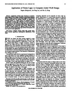
II. L INK L IFE - TIME P REDICTION M ODEL In mobile ad hoc networks, a direct consequence of node-mobility is that the network’s topology is time-variant and when the nodes’ communications fail to reach the destination, the route becomes invalid. Therefore, if we can predict the residual time of the link between two nodes, then we are capable of estimating the reliability of the link. In this section, a link life-time prediction model is proposed based on the node-mobility status, which includes the current position, the current speed and the current traveling direction of the node, which reflects the expected movement of the node in the near future. According to the relative node mobility status between two nodes, the achievable link life-time may also be calculated. We assume that there are N nodes in the network. At time-instant t, the position of the ith node Ni is (Pix,t , Piy,t ), its speed is vi,t , and its direction is θi,t . As a natural choice, the direction of the horizontal axis is assumed to be associated with the angle of 0. Similarly, the position of node Nj is (Pjx,t , Pjy,t ), its speed is vj,t , and its angular direction is θj,t . As seen in Fig. 1, the distance between node Ni
vjy
(5)
(7)
2
(vj cos(θj ) − vi cos(θi )) ](∆t) + 2[(Pjy,t+∆t − Piy,t+∆t )(vj sin(θj ) − vi sin(θi ))+ (Pjx,t+∆t − Pix,t+∆t )(vj cos(θj ) − vi cos(θi ))]∆t+ [(Pjy,t+∆t − Piy,t+∆t )2 + (Pjx,t+∆t − Pix,t+∆t )2 ]− d2max ≤ 0. Observe that Eq. (7) is a quadratic polynomial of the form Ax2 + Bx + C ≤ 0, where we have: A
=
(vj sin(θj ) − vi sin(θi ))2 + (vj cos(θj ) − vi cos(θi ))2 ,
B
=
2[(Pjy,t+∆t − Piy,t+∆t )(vj sin(θj ) − vi sin(θi )) + (Pjx,t+∆t − Pix,t+∆t )(vj cos(θj ) − vi cos(θi ))],
C
=
[(Pjy,t+∆t − Piy,t+∆t )2 + (Pjx,t+∆t − Pix,t+∆t )2 ] − d2max ,
x
=
∆t.
(8)
According to the characteristics of quadratic polynomials, the minimum real root represents the maximum link life-time as determined by the node’s limited transmission range. Observe from Eq. (8) that we have A ≥ 0, C ≤ 0. If we have A = 0, which implies that the two nodes considered have the same node mobility status, then the distance between them would never change, unless one of them changes its mobility status. Thus the life-time of the link between them is infinite. By contrast, if we have A 6= 0, and this is a relevant practical scenario, then Eq. (7) must have one and only one real root, which satisfies B√2 −4AC ≥ 0. Then, according to the simple formula of x = (−B + B 2 − 4AC)/(2A), A > 0, we may determine the maximum link life-time. III. F UZZY L OGIC BASED DSR
Nj′ (Pjx,t+∆t , Pjy,t+∆t)
Fig. 1.
The relationship between Ni and Nj
and Nj is dij,t . After a time elapse of ∆t, the position of node Ni becomes (Pix,t+∆t , Piy,t+∆t ), while its speed is vi,t+∆t and its direction is θi,t+∆t . Similarly, for node Nj , the future position becomes (Pjx,t+∆t , Pjy,t+∆t ), while the corresponding speed is vj,t+∆t , and the direction is θj,t+∆t . When predicting a specific link’s life-time, the simplest model is to consider the speed and the direction of the most recent hop only, although our future research will consider higher-oder mobility predictions, as detailed in a speech prediction context in [17]. Therefore we describe the speed and the direction of Ni and Nj at time-instant t based on this rudimentary first-order model as vi , vj , θi and θj . Pix,t+∆t
=
Pix,t + vi cos(θi ) ∆t,
(1)
Piy,t+∆t
=
Piy,t + vi sin(θi ) ∆t,
(2)
Pjx,t+∆t
=
Pjx,t + vj cos(θj ) ∆t,
(3)
Pjy,t+∆t
=
Pjy,t + vj sin(θj ) ∆t.
(4)
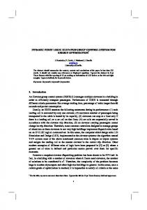
The philosophy of fuzzy logic originates from the fuzzy set theory proposed by Zadeh in 1965 [18], which has the benefit of resolving decision dilemmas, even when provided with inaccurate information by multiple inputs. A basic fuzzy logic control process consists of three parts: fuzzification, inference and defuzzification. We present the structure of a basic Fuzzy Logic System (FLS) in Fig. 2. As FLS Rules Fuzzy Sets
Crisp Input
Fuzzifier
Fig. 2.
Fuzzy Sets
Inference
Crisp Output
Defuzzifier
The structure of FLS
detailed in [18], the key steps in designing a FLS is to choose the suitable antecedents, the membership function of the input and output, the fuzzy inference rule and the defuzzification method. Since DSR is a reactive routing protocol, it only commences its route discovery process when there is data to be transmitted. Following the route discovery process, several routes are identified
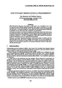
where pt is the route life-time. Based on its appealing simplicity and popularity, the so-called triangular membership function [18] is chosen to map the crisp input value into the fuzzy sets and vice versa. The output of the FLS is the route stability. We opt for using three fuzzy sets described by the loose terms ”Short”, ”Medium” and ”Long” for both the number of hops and for the route life-time. For the route stability, we use the terminology ”Low”, ”Medium” and ”High”. The simple triangular membership functions of the number of hops and path life-time are shown in Fig. 3. The membership function of the route stability has the same shape as that of the number of hops, thus we do not portray it graphically here. Moreover, the universe of the number of hops and the route stability is normalized to the range of [0, 1], while the universe of the route life-time to [0, 300s], because the route cache expiry time-out is 300s. For the triangular membership function of the route life-time, vmax denotes the maximum speed of all nodes. The classic ”IF-THEN” rule is chosen as the inference rule [18] for the mapping from the fuzzy input sets to the fuzzy output sets. For example, A is a fuzzy set defined over the universe X and B is a fuzzy set defined over the universe Y . Then the inference rule is described as ”IF A THEN B”, which is equivalent to the following fuzzy relationship: R = (A × B) ∪ (A¯ × Y ).
(10) 0
Let us now assume that there is a new antecedent A over universe X. Then we have B 0 = A0 ◦ R, (11) where B 0 is the new consequence over universe Y , and the symbol ◦ denotes the composition operation [18], while Eq. (11) presents the composition of fuzzy relations, which adopts the max-min
Membership Value
1
Short
0
Medium
0.1
Long
0.4 0.5 0.6 0.9 Normalized Number of Hops
1
Membership Value
(a)
1
Short
Medium
Long
dmax vmax
dmax 2vmax
0
2dmax vmax
300
Route Lifetime (s)
(b) Fig. 3.
No. 1 2 3 4 5 6 7 8 9
The membership function of antecedents TABLE I I NFERENCE RULE OF FLS
NumHops Short Short Short Medium Medium Medium Long Long Long
RouteLifetime Short Medium Long Short Medium Long Short Medium Long
RouteStability Medium High High Low Medium High Low Medium High
method [18]. Hence we still could get IF A0 THEN B 0 in terms of Eq. (11). The inference rule of the FLS adopted in this paper is shown in Tab I in detail. Consider the first line, for example, stating that IF the number of hops is ”Short” AND route life-time is ”short”, THEN ”route stability is ”Medium”. The weighted average method [18] is selected as the defuzzification method. The proposed FLS is incorporated in every node. The system model is shown in Fig. 4. We characterize the FL-DSR from two perspectives, namely route discovery and route maintenance. Network Layer Link min() Link Life−time Life−time Predict. Model l Eq. (9) ij
Route Life−time
pt
FLS
Route Stability
NumHops
Mobility Status
and stored in the route cache of the source node. The metric employed for deciding, which route to choose for transmitting the source data is that of minimizing the number of hops. Further route rediscovery is triggered only, when a certain link in the currently used route breaks owing to node-mobility and no redundant route or routerepair [8] is available. However, in mobile environments, opting for the lowest number of hops implies that we typically have a long distance between the individual nodes, which is likely to be associated with a low received power, a high Bit Error Ratio (BER) and a potentially short route life-time. Additionally, if we opt for finding all the routes during the one and only initial route discovery process without frequent updates, this may render the route cache information stale, especially in the face of dynamic mobility. Once a node moves out of the transmission range of the other nodes, it may happen that not only the link considered, but all the other routes which include this link in the route cache become invalid at the same time. Therefore, the conventional DSR protocol may not perform well in mobile environments. A trade-off between opting for a ”few hops having a short route life-time” and ”many hops having a high route lifetime” should be found. To strike an attractive trade-off, we propose a FL-DSR, which jointly considers the number of hops as well as the route life-time as its inputs, aiming for identifying the right balance between them. The minimum route life-time reflects the grade of route stability to some degree. The longer the route life-time, the higher the route stability. At the same time, the fewer hops the route has, the less likely that the route breaks, hence the higher the route stability becomes. We assume that there are M hops in a route. The link life-time between node Ni and Nj is described as lij , 0 ≤ i, j ≤ (M − 1), which is calculated according to the link life-time prediction model introduced in Section II. Naturally, the link having the shortest lifetime constitutes the ’bottle-neck’ of the route. Therefore, the shortest link life-time may be interpreted as the route life-time, as defined below: pt = min(lij ), 0 ≤ i, j ≤ M − 1, (9)
Network Packet
MAC Frame
Physical Layer Fig. 4. •
The system model of FL-DSR
Route Discovery: When ever a Route REQuest (RREQ) packet arrives at a node, it records the current mobility status (the position, the speed as well as the direction) and calculates the link life-time between this hop and the immediately preceding hop according to their relative mobility status. When the RREQ arrives at the destination, the expected route life-time is calculated from Eq. (9) and substituted into the Route REPly (RREP) packet, which carries the expected route life-time and the discovered route’s identifier back to the source node. During a specific route discovery process, several viable routes may be found. Then, according to the FLS, the route exhibiting the highest route stability is chosen for transmitting the data from the source to the destination.
Route Maintenance: The Source Route (SR) packet is transmitted from the source node to the destination node and carries the chosen route, identifier or descriptor. When ever the SR packet arrives at a node during the transmission process, it records the current node’s mobility status and updates the estimated link life-time for every pair of nodes, provided that there was a change in the mobility status. If any link of the selected routes breaks and no redundant or backup route is available, a Route ERRor (RERR) packet is generated by the current node of this link to notify all the nodes, which store this link in order to delete this link for their cache. Naturally, at this stage a new route discovery process has to be initiated. If a redundant route exists, it will be activated in order to salvage the packet and ultimately the session. However, we do not know, whether the redundant route has become invalid in the meantime owing to node-mobility, which may cause a data transmission failure again. Hence, according to the residual route life-time, the expiry time-out of the route in the route cache is adjusted adaptively in order to update the route information in the route cache.
IV. P ERFORMANCE C OMPARISONS FOR THREE PHYSICAL LAYER SCHEMES
In this section, we compare the achievable performance of the proposed FL-DSR and conventional DSR for three different physical layer schemes, namely for a perfect channel, for uncoded-QPSK and for Turbo Trellis Coded Modulation assisted 8PSK (TTCM8PSK) [19]. First we employed OMNeT++ [20] for creating a simulation environment in order to compare the BER performance of uncodedQPSK and TTCM-8PSK. The two nodes considered were located in a 500 × 500m2 square-shaped field. The distance between them was 100m. By appropriately adjusting the receive SNR, we recorded the BER versus SNR relationship. The BER of uncoded-QPSK was calculated from the theoretical Q-function based formula [19], while for TTCM-8PSK we used a pre-computed lookup table for the Additive White Gaussian Noise (AWGN) channel in order to generate the BER based on both the SNR and on the length of the turbo-interleaved frame. The generator polynomial used by the TTCM constituent code was [1124] in octal representation. Four iterations were invoked in the TTCM decoder. The interleaved frame size of the physical layer was varied from 100 bits to 6000 bits. The simulation results suggested that for an SNR of about 7.5dB, the BER of TTCM8PSK was 10−5 , while uncoded-QPSK required an SNR of about 12.5dB for a BER of 10−5 . This implies that TTCM-8PSK has a nearly 5dB gain compared to uncoded-QPSK at a BER of 10−5 , although naturally this gain is achieved at a higher implementational complexity. In our second investigation we considered a more complex simulation environment, where 20 nodes were uniformly located in the 500×500m2 square-shaped field, 5 nodes in each row and 4 nodes in each column. The source node was stationary at position (499, 499), and the destination node was fixed in position (0, 0). Constant Bit Rate (CBR) traffic was generated in the application layer, using a packet length of 512 Bytes and a packet generation frequency of 5 packets/second. The transport layer employed the User Datagram Protocol (UDP), while the MAC layer adopted the IEEE 802.11b standard. For the sake of excluding the packet dropping events due to buffer overflow, we set the queue length in the MAC layer to be infinite. In the physical layer, a free-space path loss model of 20 dB/Decade was assumed and an AWGN channel was used [21]. The transmit power was set to 1mW, the receive sensitivity5 was −85dBm, the Signal-to-Interference-plus-Noise Ratio (SINR) threshold was assumed to be 4dB, which requires more powerful lower-rate 5 The
receive sensitivity threshold is used to judge whether the received signal is deemed to be noise, because a signal with received power less than the sensitivity level is deemed to be noise.
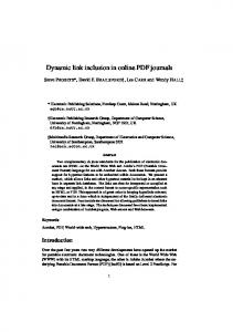
FEC coding than the above-mentioned TTCM-8PSK scheme. The bit rate over the channel was 2 Mb/s. We assumed that no interference existed amongst the nodes and that both the control packets as well as the physical layer header were received without errors. Except for the source node and destination node, all other nodes obeyed the mass mobility model6 , where the speed and the direction of each node was chosen randomly. We compared the performance of the proposed FL-DSR and conventional DSR, when the thermal noise PN was −91.8dBm, and the uniformly distributed random mobile speed was 0 − 10 m/s. The following performance metrics were compared: • Normalized Number of Route Break Events [22]: Every time when the data was not successfully forwarded to the next hop, the link between the two nodes was assumed to be broken and the number of route break events was increased by one. We normalized the number of route break events by the average number of hops; • Network Throughput [23]: The number of data bits received at the destination per second in the network layer; • The Inverse Network Control Load [23]: The number of data bits successfully delivered to the destination per the number of control bits transmitted, which may be viewed as the inverse of the number of control bits associated with the delivery of a data bit. The control bits include the bits of all routing packets and the header bits in all data packets. Each hop-based transmission of the control bits was counted. 35 Normalized Number of Route Break Events
•
30 25 20 15 10 DSR-perfect Fuzzy-perfect DSR-QPSK Fuzzy-QPSK DSR-TTCM-8PSK Fuzzy-TTCM-8PSK
5 0
0
2
4 6 Mobile Speed (m/s)
8
10
Fig. 5. The normalized number of route break events versus node speed for 20 nodes
Observe from Fig. 5, 6, and 7 that upon increasing the mobile speed, both the FL-DSR and the conventional DSR relying on the three different physical layer schemes exhibit similar trends in terms of the number of route break events, network throughput and network control load. However in Fig. 5, the number of route break events of uncoded-QPSK first decreases, then increases because the node mobility may allow the nodes to avoid idling in a deep fade, which is more clearly visible for the FL-DSR scenario. FL-DSR scheme has a lower number of route break events and a higher overall network throughput. As for the network control load characterized in Fig. 7, we observe that when the mobile speed is low, possibly 0 m/s, the FL-DSR imposes a higher network control load than the conventional DSR, because the former has to record the mobility status in the RREQ, RREP and SR packets, thus the number of control bits increases. By contrast, when the mobile speed is higher than 1 m/s, the negative impact of the extra control bits in the control packets and data packets has been mitigated by the increased node mobility, and as a result, the network control load of the FL-DSR becomes lower than 6 The mobile node moves along a straight line for a certain period of time before it makes a turn, where the length of the time is a random number. When it makes a turn, the new direction (angle) and speed are also random number. When it hits a wall, it is reflected off the wall at the same angle.
DSR-perfect Fuzzy-perfect DSR-QPSK Fuzzy-QPSK DSR-TTCM-8PSK Fuzzy-TTCM-8PSK
Network Throughput (kbits/s)
20
on the achievable performance was quantified for a perfect channel, as well as for uncoded-QPSK and TTCM-8PSK, which indicates that error-resilient coding and modulation substantially improves the performance of the network layer.
15
R EFERENCES 10
5
0
0
2
4 6 Mobile Speed (m/s)
8
10
Fig. 6. The achievable network throughput of different physical layer configurations for 20 nodes
that of conventional DSR. The reason for this phenomenon is that the FL-DSR always chooses the specific route having the highest route stability, which is loosely defined as the route having the highest resilience against any changes in the network’s topology. If the number of route break events decreases, then naturally, the number of data packets delivered to the destination increases, thus the probability of activating new route discovery processes decreases, hence the number of control packets transmitted also decreases. Naturally, 1.2
DSR-perfect Fuzzy-perfect DSR-TTCM-8PSK Fuzzy-TTCM-8PSK
Network Control Load
1
0.8
0.6
0.4
0.2
0
Fig. 7.
0
2
4 6 Mobile Speed (m/s)
8
10
The comparison of the Inverse of network Control Load
TTCM-8PSK performs worse than an idealized perfect channel, since it requires an SNR of 7.5dB for maintaining a BER of 10−5 , hence the data packets may suffer from bit errors. Uncoded-QPSK performs even more poorly, since it necessitates an SNR of 12.5dB for maintaining a BER of 10−5 , hence virtually, no data is delivered to the destination node successfully in the scenario considered. The number of route break events is high and the network throughput is close to zero, hence the inverse of the network control load is also close to zero. Therefore TTCM-8PSK outperforms uncoded-QPSK in terms of its network layer performance, which underlines that the suitable configuration of the physical layer is vitally important for achieving a desirable network layer performance. V. C ONCLUSIONS This paper proposed a novel FL-DSR protocol in order to process multiple inputs potentially providing imprecise information, which jointly considered the number of hops and the route life-time, when choosing the route having the highest route stability. The simulation results confirmed that the FL-DSR outperforms the conventional DSR, since it decreased the number of route break events, improved the network throughput, while reducing the network control load. At the same time, the impact of different physical layer schemes
[1] Q. Zhang and Y.-Q. Zhang, “Cross-layer design for QoS support in multihop wireless networks,” Proceedings of the IEEE, vol. 96, no. 1, pp. 64–76, Jan. 2008. [2] F. Fu and M. van der Schaar, “A new systematic framework for autonomous cross-layer optimization,” IEEE Transactions on Vehicular Technology, vol. 58, no. 4, pp. 1887–1903, May 2009. [3] G. Carofiglio, C.-F. Chiasserini, M. Garetto, and E. Leonardi, “Route stability in MANETs under the random direction mobility model,” IEEE Transactions on Mobile Computing, vol. 8, no. 9, pp. 1167–1179, Sept. 2009. [4] M. Al-Akaidi and M. Alchaita, “Link stability and mobility in ad hoc wireless networks,” IET Communications, vol. 1, no. 2, pp. 173–178, April 2007. [5] I. Rubin and Y.-C. Liu, “Link stability models for QoS ad hoc routing algorithms,” in Proc. 58th IEEE on Vehicular Technology Conference VTC 2003-Fall, vol. 5, 6–9 Oct. 2003, pp. 3084–3088. [6] K.-T. Feng, C.-H. Hsu, and T.-E. Lu, “Velocity-assisted predictive mobility and location-aware routing protocols for mobile ad hoc networks,” IEEE Transactions on Vehicular Technology, vol. 57, no. 1, pp. 448–464, Jan. 2008. [7] S.-Y. Ni, Y.-C. Tseng, Y.-S. Chen, and J.-P. Sheu, “The broadcast storm problem in a mobile ad hoc network,” in Proc. 5th ACM/IEEE on Mobile computing and networking MobiCom ’99. ACM, 1999, pp. 151–162. [8] D. Johnson, Y. Hu, and D. Maltz, “The dynamic source routing protocol (DSR) for mobile ad hoc networks for IPv4 (RFC 4728),” IETF Draft, 2007. [9] P. Klement, E. P. Klement, W. Slany, and W. Slany, Fuzzy Logic in Artificial Intelligence, 1994. [10] C.-C. Lee, “Fuzzy logic in control systems: fuzzy logic controller. I,” IEEE Transactions on Systems, Man and Cybernetics, vol. 20, no. 2, pp. 404–418, Mar./Apr. 1990. [11] N. Baldo and M. Zorzi, “Fuzzy logic for cross-layer optimization in cognitive radio networks,” IEEE Communications Magazine, vol. 46, no. 4, pp. 64–71, April 2008. [12] X.-S. Xia, Q.-C. Ren, and Q.-L. Liang, “Cross-layer design for mobile ad hoc networks: energy, throughput and delay-aware approach,” in Proc. IEEE on Wireless Communications and Networking Conference WCNC 2006, vol. 2, 3–6 April 2006, pp. 770–775. [13] W. El-Hajj, A. Al-Fuqaha, M. Guizani, and H.-H. Chen, “On efficient network planning and routing in large-scale MANETs,” IEEE Transactions on Vehicular Technology, vol. 58, no. 7, pp. 3796–3801, Sept. 2009. [14] W. El-Hajj, D. Kountanis, A. Al-Fuqaha, and M. Guizani, “A fuzzybased hierarchical energy efficient routing protocol for large scale mobile ad hoc networks (FEER),” in Proc. IEEE on Communications ICC ’06, vol. 8, June 2006, pp. 3585–3590. [15] S. Rea and D. Pesch, “Multi-metric routing decisions for ad hoc networks using fuzzy logic,” in Proc. 1st International Symposium on Wireless Communication Systems ISWCS 2004, 20–22 Sept. 2004, pp. 403–407. [16] ——, “Fuzzy logic routing with load-balancing using a realistic mobility model,” in Proc. 61st IEEE on Vehicular Technology Conference VTC 2005-Spring, vol. 4, 30 May–1 June 2005, pp. 2611–2615. [17] R.-A. Salami, F.-C.-A. B. L. Hanzo, and R. Steele, Speech Coding, 2nd ed., R. Steele and L. Hanzo, Eds., 1999. [18] T. J. Ross, Fuzzy Logic With Engineering Applications. New York: McGraw-Hill, Inc., 1995. [19] L. Hanzo, S.-X. Ng, T. Keller, and W. Webb, Quadrature Amplitude Modulation: From Basics to Adaptive Trellis-Coded, Turbo-Equalised and Space-Time Coded OFDM, CDMA and MC-CDMA Systems, 2nd ed. Wiley-IEEE Press, 2004. [20] A. Varga and R. Hornig, “An overview of the OMNeT++ simulation environment,” in Proc. 1st international conference on Simulation tools and techniques for communications, networks and systems & workshops Simutools ’08, 2008, pp. 1–10. [21] A. Goldsmith, Wireless Communications. New York: Cambridge University Press, 2005. [22] Z.-G. Hu, R. Hu, and H. Ma, “A route reliability algorithm for mobile ad hoc networks,” in Proc. International Conference on Wireless Communications, Networking and Mobile Computing WCNM 2005, vol. 2, 23–26 Sept. 2005, pp. 787–790. [23] C.-E. Perkins, E.-M. Royer, S.-R. Das, and M.-K. Marina, “Performance comparison of two on-demand routing protocols for ad hoc networks,” IEEE Personal Communications, vol. 8, no. 1, pp. 16–28, Feb 2001.