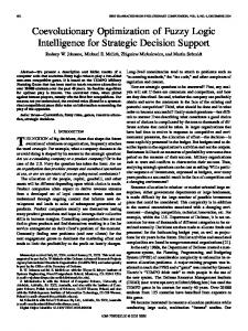
Fuzzy Logic and Neuro-fuzzy Modelling of Diesel Spray Penetration: a comparative study S.H.Lee, R.J.Howlett, C.Crua & S.D.Walters Intelligent Systems & Signal Processing Laboratories, Engineering Research Centre, University of Brighton, Moulsecoomb, Brighton, BN2 4GJ, UK. Email:
[email protected],
[email protected],
[email protected] &
[email protected] Abstract: The aim of this study was to demonstrate the effectiveness of an adaptive neuro-fuzzy inference system (ANFIS) for the prediction of diesel spray penetration length in the cylinder of a diesel internal combustion engine. The technique involved extraction of necessary representative features from a collection of raw image data. A comparative evaluation of two fuzzy-derived techniques for modelling fuel spray penetration is described. The first model was implemented using a conventional fuzzy-based paradigm, where human expertise and operator knowledge were used to select the parameters for the system. The second model used an adaptive neuro-fuzzy inference system (ANFIS), where automatic adjustment of the system parameters was effected by a neural network based on prior knowledge. Two engine operating parameters were used as inputs to the model; namely in-cylinder pressure and air density. Spray penetration length was modelled on the basis of these two inputs. The models derived using the two techniques were validated using test data that had not been used during training. The ANFIS model was shown to achieve an improved accuracy compared to a pure fuzzy model, based on conveniently selected parameters. 1 Introduction In a diesel engine, the combustion and emission characteristics are influenced by fuel atomisation, nozzle geometry, injection pressure, shape of inlet port, and other factors. In order to improve air-fuel mixing, it is important to understand the fuel atomisation and spray formation processes. Researchers have investigated the characteristics of the spray behaviour, formation and structure for the high-pressure injector by experimental and theoretical approaches in order to improve the combustion performance and reduce exhaust emissions. However, further detailed studies of the atomisation characteristics and spray development processes of high-pressure diesel sprays are still relevant. When dealing with research and design associated with combustion processes are often difficulties encountered in handling situations in which there are many variables involved. To adequately model and predict the behaviour of combustion, consideration of non-linear multi-variant inter-relationships are required, often in a ‘noisy’ environment. For example, in the prediction of performance, modelling or control of a combustion process from the point of view of energy efficiency, prediction of boiler emissions, or control of an internal combustion (IC) engine, there are numerous variables involved. The precise interactions of the variables are not fully understood, hence cannot easily be modelled by an unaided human investigator. Intelligent systems, i.e. software systems incorporating artificial intelligence, have shown many advantages in engineering system control and modelling. They have the ability to rapidly model and learn characteristics of multi-variant complex systems, exhibiting advantages in performance over more conventional mathematical techniques. This has led to them being applied in diverse applications in power systems, manufacturing, optimisation, medicine, signal processing, control, robotics, and social/psychological sciences [1, 2]. Fuzzy logic is a problem-solving technique that derives its power from its ability to draw conclusions and generate responses based on vague, ambiguous, incomplete and imprecise information. To simulate this process of human reasoning, it applies the mathematical theory of fuzzy sets first defined by Zadeh, in 1965 [3]. Fuzzy inference is the process of formulating a mapping from a given input value to an output value using fuzzy logic. The mapping then provides a basis from which decisions can be made, or patterns discerned. It has been proven that the system can effectively express highly non-linear functional relationships [4]. Fuzzy inference systems (FIS) have been
successfully applied in fields such as automatic control, data classification, decision analysis, expert systems and computer vision. Virtual sensing techniques using neural networks have been successfully demonstrated as replacement for physical sensors, for example the virtual lambda sensor, which uses a neural network for the estimation of air-fuel ratio [5, 6] and for the detection of engine misfire [7]. This technique allows hardware to be replaced by software and so potentially can reduce costs. It has also been demonstrated that fuzzy control paradigms can be beneficially applied to small engines with only a minimal sensor requirement [8, 9, 10, 11 & 12]. In these studies, fuzzy control has been shown to provide a convenient calibration procedure that has the potential to lower costs through reducing the effort required in calibrating the engine. Adaptive Neuro-Fuzzy Inference Systems (ANFIS), developed in the early 1990s by Jang [13], combine the concepts of fuzzy logic and neural networks to form a hybrid intelligent system that enhances the ability to automatically learn and adapt. Hybrid systems have been used by researchers for modelling and predictions in various engineering systems. ANFIS was used to predict strength of material based on compositions and microstructure e.g. size of graphite flake from a collection of experimental for data [14]. The basic idea behind these neuro-adaptive learning techniques is to provide a method for the fuzzy modelling procedure to learn information about a data set, in order to automatically compute the membership function parameters that best allow the associated FIS to track the given input/output data. The membership function parameters are tuned using a combination of the least squares estimation and the backpropagation algorithm for estimation of membership function parameters. These parameters associated with the membership functions are adapted through the learning process in a similar way to training a neural network. Their adjustment is facilitated by a gradient vector, which provides a measure of how well the FIS is modelling the input/output data for a given set of parameters. Once the gradient vector is obtained, any of several optimisation routines could be applied in order to adjust the parameters so as to reduce error between the actual and desired outputs. This allows the fuzzy system to learn from the data it is modelling. The approach has the advantage over the pure fuzzy paradigm that the need for the human operator to tune the system by adjusting the bounds of the membership functions is removed. Many related combustion problems are exactly the types of problems and issues for which an Artificial Intelligence (AI) approach appears to be most applicable; the potential exists for making better, quicker and more accurate predictions than with traditional methods. The increasing availability of advanced computer equipment and sensory systems frequently results in the production of large amounts of information-rich data, and there are often inadequate means of analysing it, so as to extract meaning. The aim of this investigation has been to apply intelligent systems tools and techniques to achieve an improved ability to analyse large complex data sets generated during engine research, in a semi-automated way. An intelligent paradigm has been created based on a fuzzy logic inference system combined with conventional techniques. 2
Methods
2.1 Pure Fuzzy Logic Model Fuzzy logic provides a practicable way to understand and manually influence the mapping behaviour. In general, fuzzy logic uses simple rules to describe the system of interest, rather than analytical equations, making it easy to implement. An advantage, such as robustness and speed, fuzzy logic is one of the best solutions for system modelling and control. An FIS contains three main components, the fuzzification stage, the rule base and the defuzzification stage. The fuzzification stage is used to transform the so-called crisp values of the input variables into fuzzy membership values. Then, these membership values are processed within the rule-base, using conditional ‘if-then’ statements. The outputs of the rules are summed and defuzzified into a crisp analogue output value. The effects of variations in the parameters of a FIS can be readily understood and this facilitates calibration of the model. The system inputs, which in this case are the in-cylinder pressure and the air density, are called linguistic variables, whereas ‘high’ and ‘very high’ are linguistic values which are characterised by the membership function. Following the evaluation of the rules, the defuzzification transforms the fuzzy membership values into a crisp output value, for example, the diesel spray penetration length. The complexity of a fuzzy logic system with a fixed input-output structure is determined by the number of membership functions used for
the fuzzification and defuzzification and by the number of inference levels. The block diagram of a general fuzzy logic system is shown in Figure 1, where: x1, x2,…xn stand for n crisp inputs and y is the crisp output. x1 x2
x3
xn
Crisp inputs
Fuzzification
Inference of Rule 1
Inference of Rule 2
Inference of Rule n
Aggregation Defuzzification
y Crisp output
Figure 1: Block diagram of a general fuzzy logic system A fuzzy system of this kind requires a knowledgeable human operator to initialise the system parameters e.g. the membership function bounds. The operator must then optimise these parameters to achieve a required level of accuracy of mapping of the physical system by the fuzzy system. While the visual nature of a fuzzy system facilitates the optimisation of the parameters, the need for it to be accomplished manually is a disadvantage. 2.2 ANFIS Model An ANFIS largely removes the requirement for manual optimisation of the fuzzy system parameters. A neural network is used to automatically tune the system parameters, for example the membership function boards, leading to improved performance without operator intervention. In addition to a pure fuzzy logic approach, an ANFIS was also developed for the estimation of spray penetration length because the combination of neural network and fuzzy logic enables the system to learn and improve its performance based on past data. The neuro-fuzzy system with the learning capability of a neural network and with the advantages of the rule-based fuzzy system can improve the performance significantly and can provide a mechanism to incorporate past observations into the classification process. In a neural network the training essentially builds the system. However using a neuro-fuzzy scheme, the system is built by fuzzy logic definitions and then it is refined using neural network training algorithms. 2.2.1 Architecture The initial membership functions and rules for the FIS are designed by employing human knowledge about the target system to be exploited. The ANFIS can then refine the fuzzy ‘if-then’ rules and membership functions to describe the input/output behaviour of a complex system. In practical applications Sugeno type FISs have been considered more suitable for constructing fuzzy models due to their more compact and computationally-efficient representation of data than the Mamdani fuzzy systems. A typical zero-order Sugeno fuzzy system has the form: If x is A and y is B then z = c where A and B are fuzzy sets and z is a crisply defined function. A singleton spike is often completely sufficient to cater for the needs of a given problem. Alternatively, a more general first-order Sugeno can be used by setting the consequent to a higher order function, for example z = px + qy + c.
Layer 1
Layer 2
Layer 3
Layer 4 x
x
A1
W1
Layer 5
y
ϖ1
ϖ1 f f
A2
ϖ2
B1
y
B2
ϖ2 f
W2 x Adaptive node
y
Fixed node
Figure 2: ANFIS Sugeno fuzzy system. However a higher-order system often adds an unwarranted level of complexity because of the algorithm needed to optimise the parameters. For this reason a zero-order Sugeno FIS is used in this investigation. Figure 2 shows the equivalent ANFIS architecture which consisted of five layers [13]. The nodes in the input layer are adaptive. Any appropriate membership functions can be used. In this experiment generalised bell-shaped membership functions were chosen to describe the input parameters because of their smoothness and concise notation. Variables x and y form input values of A1, A2 and B1, B2 respectively. A1, A2, B1 and B2 are the linguistic labels (small, large, etc.) used in the fuzzy theory for dividing the membership functions. The membership relationship between the output and input in this layer can be expressed as:
O1,i = µ Ai ( x), i = 1, 2
(1)
O1, j = µ B j ( y ),
(2)
where
j = 1, 2
O1,i and O1, j represent the output functions, µ Ai and µ B j are the membership functions
Layer 2, sometimes referred to as the ‘rule layer’ consists of two fixed nodes which represent the fuzzy strengths of each rule. The product rules can be used to calculate the weighting function for the fuzzy operator ‘AND’ of a Sugeno FIS. The output W1 and W2 are the weight functions for the next layer. The input and output relationship in this layer is:
O2,i = Wi = µ Ai ( x) µ Bi ( y ) i = 1,2 where
(3)
O2,i is the output of layer 2.
The third layer is the normalised layer and its function is to normalise the weight function.
O3,i = ϖ i = where
ωi
ω1 + ω2
i = 1,2
O3,i is the layer 3 output
(4)
The fourth layer containing adaptive nodes is the defuzzification layer. The output from this layer is:
ϖ ( px + qy + r ), where pi , qi and ri are the consequent parameters of the node. The input and output relationship in this layer can be defined as:
O4,i = ϖ i f i = ϖ i ( pi x + qi y + ri ) i = 1,2 where
(5)
O4,i is the layer 4 output.
The fifth layer consists of a single fixed node, it is the summation of the weighted output of the consequent parameters in layer 4. The output layer is given by:
O5,i = ∑ϖ i f i = i
∑ω f ∑ω
i i
i
i
i = 1,2..
(6)
i
Although any feed-forward network can be used in an adaptive network-based fuzzy inference system, Jang [13] implemented a hybrid learning algorithm that converges much faster than using gradient descent method alone. During the forward pass, the node outputs advance until the output membership function layer, where the consequent parameters are identified by the least-squares method. The backward pass uses a backpropagation gradient descent method to update the premise parameters, based on the error signals that propagate backward. Under the condition that the premise parameters are fixed, the consequent parameters determined are optimal. This reduces the dimension of the search space for the gradient descent algorithm, thus ensuring faster convergence. 3
Experimental Apparatus
3.1 Rapid Compression Machine The spray rig facility was designed specifically to enable the gaps in the current literature (spray and combustion analysis of injections into environments above 6 MPa) to be addressed, in addition to providing a means of testing sprays at conditions anticipated for the next generation of diesel engines. This rapid compression machine is based around a single cylinder Ricardo Proteus test engine which was converted to two-stroke cycle operation by the addition of inlet and exhaust ports in the cylinder liner. This approach significantly increased the room available in the cylinder head for optical access by the removal of inlet and exhaust valves and also allowed reduced mechanical complexity, thus cutting down on engine build times. The engine had a bore of 135 mm, a stroke of 150 mm, and a displacement of 2.2 litres. The cylinder head was heated by a water jacket (90°C) and the sump oil by immersion heaters (85°C). This enabled the engine to be heated prior to motored testing, and minimising heat losses from the compressed gas to the cylinder wall. A water-cooled Kistler pressure-transducer attached to a storage oscilloscope was used to monitor the incylinder pressure. The Proteus was driven by a dynamometer through a 90° gearbox shown in Figure 3. The output shaft of the gearbox was connected to the Proteus flywheel and, with a reduction ratio of 6:1, reduced the dynamometer speed of 3000 rpm to 500 rpm engine speed. This was the operating engine speed for all the tests carried out in this work. The fuel rail and delivery pipe were both instrumented with Kistler pressure transducers. The pipe from the rail to the injector was kept short, representative of a real vehicle system. The fuel injector used was a modern electro-magnetically actuated common rail injector. This injector was specially equipped with a needle lift sensor to obtain the exact needle position during the injection. The injector nozzles were interchangeable and therefore allowed testing of different nozzle types and nozzle hole diameters. A custom-built controller was developed [15] to enable independent control of injection timing, number of injections per cycle, injection duration and rail pressure. This unit essentially consisted of a microprocessor dedicated to the task of triggering the injector and a secondary device (such
as a laser system, flashgun or CCD camera). The custom controller also allowed control of initial needle drive current and PID control of the fuel rail pressure. Before each series of experiments, a personal computer was used to upload the injection parameters to the Fuel Injection Equipment (FIE) unit (e.g. injection angle, injection duration, rail pressure, delay of secondary trigger, etc.). This gave high timing accuracy and good parameter control. For the entire experimental work low-sulphur Esso AF1313 diesel reference fuel was used.
Figure 3: Rapid compression machine and optical combustion chamber 3.2 Optical Combustion Chamber An optical chamber 80 mm in length and 50 mm in diameter was fitted on to the cylinder head to enable the full length of the developed fuel spray to be viewed. This chamber provided a near quiescent high-pressure environment, with realistic in-cylinder conditions being achieved by conditioning of the intake air. The size and cylindrical shape of the chamber offered sufficient space for the fuel spray to develop without wall impingement. The flow field in the chamber was quiescent to avoid disturbances by airflow motion on the spray development. The compression ratio of the engine was reduced to 9:1 to further increase the volume available for the optical chamber. In-cylinder temperatures and pressures representative of a modern engine were obtained by increasing the boost pressure and temperature up to 0.8 MPa and 100°C. The induced air was then compressed in the engine during the compression stroke to achieve the desired test conditions. Optical access into the chamber was provided by four removable sapphire windows giving an optical access 25 mm wide and 55 mm high. The design was optimised to allow many state of the art optical techniques to be applied and enable both qualitative and quantitative measurements of fuel, air and combustion products. The windows were easily removable for cleaning or replacement. The windows were taken out and fully cleaned every day. The effect of window fouling on the images was assessed by running the engine at the same conditions before and after cleaning the windows. Comparing the results, it was subjectively concluded that the fouling of the windows did not noticeably alter the quality of the images for non-fired studies (e.g. liquid and vapour imaging). Window fouling for fired tests was not significant if the windows were cleaned twice daily. The fact that the camera’s depth of field was kept small for all studies helped achieve good quality images by focusing only on the plane of interest.
3.3 Spray Visualisation The CCD video camera used in this series of experiments was a Kodak Ektapro HS Motion Analyzer (model 4540), with a recording rate adjustable from 30 to 4500 frames per second (fps) at full resolution (256×256 pixels × 256 grey levels), and from 9000 to 40500 fps at progressively reduced resolution. The best compromise between acquisition rate and image resolution was obtained with a frame rate of 18000 to 27000 fps, with a corresponding resolution of 256×64 pixels, and 128×64 pixels, respectively. The sprays were backlit by a halogen flood light fitted with a diffuser, and the high-speed camera was setup as shown in Figure 4.
Common rail injector
Piston High-speed video camera Figure 4: Setup for high-speed video recording The processing of the videos was performed by purpose-developed software that measured the spray penetration length and spray cone angle at each video frame after suitable pixel thresholding [16]. The images were processed and thresholded to pick out the spray outline from the background. The threshold level was subjectively chosen by selecting one image from the batch of images generated by a test run and varying the threshold to obtain optimum results. Since the quality of images remained the same during a test run, this threshold value was suitable for all the images in that batch. The maximum spray penetration was calculated by finding the spray pixel furthest from the nozzle. The software was used to calculate the spray penetration and dispersion angle for each frame of every video. Repeatability tests were performed to assess the variability in penetration for a range of test conditions. The variation in spray tip penetration length was found to be ±4% from the average curve. The camera resolution was measured to be 0.3 mm per pixel, hence the overall uncertainty was estimated to be ±6%. The calculated results were found to be insensitive to the threshold level chosen with a 12.5% variation in threshold level giving a 1% change in measured penetration [14]. 4 Experimental Work A large collection of spray data was generated using the Ricardo Proteus test engine. These data comprised images depicting the spray patterns of diesel injection processes, under selected conditions of relative pressure, nozzle size and type and in-cylinder air temperature. The images representing time-varying spray patterns under each relative pressure condition were examined and processed using a thresholding technique; each image representing the instant of maximum penetration length was then determined, yielding a maximum penetration value which could be linked with its corresponding relative pressure across the injector. The collected maximum spray penetration values and corresponding relative pressures then formed labelled data to be modelled by the FIS as shown schematically in Figure 5.
Image database Greyscale images
Image t=0
Threshold to monochrome
Monochrome images
Extract maximum penetration length
Image t=1 Max. penetration value
Image t=2
Image t=n
Pure Fuzzy Logic Inference System/Adaptive Neuro-fuzzy Inference System (ANFIS)
Optimised model
Diesel spray model
Figure 5: Schematic diagram of FIS modelling
4.1 Pre-processing Raw penetration lengths were plotted against time under each relative pressure and density condition. Polynomial fitting was employed to produce best fitted curves where maximum penetration values can be depicted. As an example, Figure 6 shows a selected plot when relative pressure is 60MPa and air density is 14kg/m3.
Figure 6: Selected polynomial curves fitting & maximum spray penetration seeking Various values of relative pressure and density were selected and the resulting maximum penetration was recorded. These were combined into vectors which were used in the training of the ANFIS, as illustrated in Table 1.
Table 1: Training data sets and results Parameters Measured penetration (mm)
Data set
Relative pressure (MPa)
1 2 3 4 5 6
60 60 100 100 160 160
3
Density (kg/m )
14 35 14 35 14 35
53 32 52 38 54 36
4.2 Pure Fuzzy Inference Model Figure 7 illustrates the fuzzy sets which were used in the pure fuzzy logic inference system. There were two stages in the inference model, the in-cylinder pressure and the air density; both stages are described in detail. The pressure and density range from 60MPa - 160MPa and 14kg/m3 - 42kg/m3 respectively. Both incylinder pressure and air density fuzzy sets used generalised bell-shaped membership functions for classes low, medium and high. These were empirically selected based on the features of all data under consideration although in many cases membership functions are fixed and somewhat arbitrarily chosen. The process was carried out by examining the ranges of all data sets to determine where the majority of points were located. The functions were also created to have an approximately equal amount of overlap between each membership curve. Experimental adjustment of the limits of the membership classes enabled the response of the model to be tailored to the experimental output from the experimental data. The rule structure is essentially predetermined by the user’s interpretation of the characteristics of the input parameters in the model. The contents of these rule-base and membership functions undertake many modifications as part of the process of heuristic optimisation and in many cases it is a continuing process. Examples of the rules initially contained in the rule-base for the pure fuzzy model are shown in Table 2. Table 2: Fuzzy rule-base IF Pressure = Low AND Density = Low THEN Penetration = Large IF Pressure = Low AND Density = Med THEN Penetration = Small IF Pressure = Low AND Density = High THEN Penetration = Small IF Pressure = Med AND Density = Low THEN Penetration = Medium IF Pressure = Med AND Density = Med THEN Penetration = vLarge IF Pressure = Med AND Density = High THEN Penetration = vSmall IF Pressure = High AND Density = Low THEN Penetration = Large IF Pressure = High AND Density = Med THEN Penetration = Medium IF Pressure = High AND Density = High THEN Penetration = vSmall
Figure 7: Fuzzy sets
Figure 8: Pure fuzzy logic model – surface plot
The fuzzifed values for the outputs of the rules were classified into membership sets similarly to the input values. While the output membership functions could have been trapezoidal or triangular, in this case, output singletons were used which have a compact form and are a computationally efficient representation. The fuzzy output singletons were defuzzified to a crisp value of penetration length by means of the widelyused centre of gravity method. The control surface in Figure 8 shows the crisp value of penetration depth at different combinations of incylinder pressure and air density using a pure fuzzy logic model. Each of these intersection points indicates the differing predicted value of spray penetration depth, which is determined by the design of the fuzzy sets, rule-base and membership functions. The surface plot acts as a practical means of determining the output needed for each combination of input parameters. 4.3 Neuro-fuzzy Model An FIS was devised using the Matlab® based application, ANFIS. A neuro-adaptive learning technique facilitated the learning of information about the data set by the fuzzy modelling procedure, in order to compute the membership function parameters that best allowed the associated FIS to track the given input/output data, rather than choosing the parameters associated with a given membership function arbitrarily. A Matlab programme was generated and compiled. The pre-processed input/output spray vector matrix which contained all the necessary representative features, was used to train the FIS. Figure 9 shows the structure of the ANFIS; a Sugeno FIS was used in this investigation. Figure 10 shows the fuzzy rule architecture of the FIS which consisted of 9 fuzzy rules. During training in ANFIS, 12 sets of pre-processed data were used to conduct 180 cycles of learning. Figure 11 shows the final membership functions under two different air input conditions derived by training using the generalised bell-shaped membership function.
Figure 9: The ANFIS model structure
Figure 10: Fuzzy rule architecture of the generalised bell-shaped membership functions
Figure 11: Fuzzy sets
Figure 12: Surface plot showing relationship between input and output parameters
5 Results and Discussion Table 3 shows the predicted penetration length obtained from the ANFIS. Figure 12 depicts a threedimensional plot that represents the mapping from relative pressure and air density to spray penetration length. As the relative pressure and air density increases, the predicted penetration length increases in a non-linear piecewise manner, this being largely due to non-linearity of the characteristic of the input vector matrix derived from the raw image data. This assumes that these raw image data are fully representative of the features of the data that the trained FIS is intended to model. However the data are inherently noisy and training data may not always faithfully represent all the features of the data that should be presented to the model. Therefore, the accuracy of the model will be adversely affected under such circumstances. 5.1 Model Validation The data in Table 3 was used as testing data to see how well the FIS model could predict the corresponding penetration length. Figure 13 shows the scatter plot of the measured and FIS-modelled penetration length utilising six sets of testing data. These two diagrams demonstrate that the predicted values are close to the experimentally-measured values, as many of the data points fall very close to the diagonal (dotted) line, indicating good correlation. Figure 14 shows similar comparisons between the FIS-modelled and measured values of the penetration length using the same testing data. Clearly the model created by ANFIS has a better agreement than the pure fuzzy logic model. The correlation coefficient also suggested identical findings.
Data set 1 2 3 4 5 6
Parameters
Table 3: Testing data and results Penetration (mm)
Relative pressure (MPa)
Density (kg/m )
60 60 100 100 160 160
3
28 40 28 40 28 40
Measured
Pure Fuzzy Paradigms
ANFIS
33 35 40 29 40 30
30 28 40 23 39 21 0.971
33 35 41 29 40 30 0.997
Correlation coefficient
Heated air
Penetration modelled (mm)
50 Pure Fuzzy Logic
45
ANFIS modelled 40 35 30 25 20 20
25
30
35
40
45
Penetration measured (mm)
Figure 13: Scatter plot of measured penetration and predicted penetration
Heated air 45 Measured Pure Fuzzy Logic
Penetration (mm)
40
ANFIS modelled 35 30 25 20 0
1
2
3
4
5
6
7
Data set
Figure 14: Comparisons between predicted and measured penetration
5.2 Discussion The ANFIS is a non-linear computational method that has potential for modelling complex systems with unclear input to output relationships due to its ability to combine fuzzy logic and system identification techniques in a hybrid manner. This type of system has several advantages when assigned to applications in which only partial knowledge of the system characteristics are known, as is typically the case with
engineering systems. Additionally, the ANFIS can rapidly identify important characteristics of the data, which is an important and useful feature of models used for estimation purposes in IC engine research. In the experiment, an ANFIS was used to predict changes in diesel spray penetration depth as a potential means to monitor impending changes in combustion chamber and fuel injector design. As an initial step toward modelling and prediction with an ANFIS for this particular application, it has proven very useful for short-term prediction of penetration depth using engine operating parameters as the input. The correlation coefficient reflects a model’s ability to predict the output based on the input used. While both models performed well and approximated the output function to a reasonable extent, the ANFIS model exhibited improved performance in this respect. Pure fuzzy logic models were conveniently constructed whilst the ANFIS performed better in cases where the input to output relationships became more complex. The pure fuzzy paradigm exhibited a larger error value than the ANFIS; better results could be achieved through experience as part of the process of rule-base and membership function optimisation. Nevertheless, the pure fuzzy logic model was quick and easy to construct. It is based on natural language which is the basis for human communication. This observation underpins many of other statements about fuzzy logic. 6 Conclusions and Projected Further Work This paper demonstrated that fuzzy and neuro-fuzzy techniques can be used to model diesel fuel spray penetration for an internal combustion engine, leading to convenient and quick investigation of the effect of penetration length under different operating parameters; in-cylinder pressure, density, air temperature, etc. The pure fuzzy logic and neuro-fuzzy system, ANFIS, employed in this work were quick and robust. They have been applied to sets of pre-processed raw diesel engine spray data and successfully compared. The pure fuzzy logic model employed simple calibrated membership functions and nine optimised rules to represent a diesel spray input/output mapping whilst the neuro-fuzzy model has based on a total of six sets of experimental image data which were used for training the FIS. Both devised models were validated by comparing the predicted results against the experimental data. The correlation coefficient of the penetration lengths estimated by ANFIS is 0.997. The pure fuzzy logic model has a smaller figure of 0.971 indicating a poorer correlation with this model. These fuzzy models set an example of how intelligent systems and signal processing techniques can be used in diesel spray modelling. The system is very conducive to improvement and adjustment and it can be fine-tuned and improved over time when more engine operating parameters become available. Trials will be conducted with larger training data sets in the expectation of obtaining higher accuracy results. It is intended that the method will be extended to involve other engine parameters. Moreover, these techniques and ideas can conveniently be extended to, and be invaluable for, other combustion systems such as modelling and emission predictions in: boilers, furnaces and incinerators. Also, for internal combustion engines, potential applications include modelling and control of: spark ignition engines and gas engines.
Acknowledgements • This work has been funded by the European Union under the Interreg III Programme of the European Regional Development Fund, Project Number 126, ‘Intelligent Engine II’. • The authors gratefully acknowledge the contribution of Dr. Steve Begg, EPSRC Loans Pool and Ricardo Consulting Engineers Ltd in providing data and equipment for this paper respectively.
References [1] Kalogirou S.A. Applications of artificial neural-networks for energy systems, Appl. Energy 67 pp.17– 35, 2000. [2] Xu K., Luxmoore A.R., Jones L.M., Deravi F., Integration of neural networks and expert systems for microscopic wear particle analysis, Knowledge-Based Systems 11 pp.213–227, 1998. [3] Zadeh L.A. Fuzzy sets, Information Control 8 pp.338–353, 1965. [4] Wang L.X. Fuzzy systems are universal approximators. Proceedings of the IEEE International conference on Fuzzy Systems, pp.1163-1170, 1992. [5] De Zoysa, M.M., Howlett, R.J. and Walters, S.D. Measurement of air-fuel ratio in internal combustion networks using neural networks. Proc. Second ICSC Symposium on the Engineering of Intelligent Systems, EIS2000. June. University of Paisley, Scotland, UK, Paper No.1304-054, 2000 [6] Howlett, R.J., de Zoysa M.M. and Walters, S.D. Monitoring IC Engines using Neural Networks. Sixth International Conference on Engines for Automobiles, ICE’2003. September. Capri, Italy, pp.291318, 2003. [7] Walters, S. D. and Howlett, R. J. Combustion quality monitoring using neural network analysis of ignition spark vectors. International Journal COMADEM. COMADEM International, UK. Vol. 5, No. 1, pp.14-20, 2002. [8] Howlett R. J., Louvet S. and Walters S. D., A Virtual Engine for the Investigation of Engine Management Strategies based on a Fuzzy Control, Paper: 03A2027, 4th International Conference on Control and Diagnostics in Automotive Applications, CD-AUTO-03, 2003. [9] Lee S.H., Howlett R.J. and Walters S.D. A Fuzzy Control System for a Small Gasoline Engine. Seventh International Conference on Knowledge-Based Intelligent Information and Engineering Systems, KES 2003. September. Oxford, UK, pp.722-732, 2003. [10] Lee S.H., Howlett R.J. and Walters S.D.. Emissions Reduction for Small Gasoline Engine Using Fuzzy Control. IFAC Symposium “Advances in Automotive Control”, Salerno, Italy, pp.200-205, April, 2004. [11] Lee S.H., Howlett R.J. and Walters S.D. Engine fuel injection control using fuzzy logic. Total Vehicle Technology Conference, Brighton, UK, pp.287-296, 2004. [12] Lee S.H., Howlett R.J. and Walters S.D. Small Engine Control by Fuzzy Logic. International Journal of Intelligent and Fuzzy Systems, pp.207-217, 2004. [13] Jang J. ANFIS: Adaptive network-based fuzzy inference systems, IEEE Transactions on Systems, Man, and Cybernetics 23, pp.665-685, 1993. [14] Qian H, Xia Bocai, Li S, Wang F. Fuzzy Neural Network Modelling of Material properties. Journal of Materials Processing Technology 122, pp.196-200, 2002. [15] Kennaird D.A., Crua C., Heikal M., Morgan R., Bar F. and Sapsford S. Computational and Experimental Methods in Reciprocating Engines, I.Mech.E. Conf. trans., London (UK), pp.179-188, November 2000. [16] Crua C. Combustion Processes in a Diesel Engine. PhD Thesis, University of Brighton (UK), 2002. [17] Howlett R.J., de Zoysa M.M., Walters S.D. and Howson P.A. Neural Network Techniques for Monitoring and Control of Internal Combustion Engines, Int. Symposium on Intelligent Industrial Automation 1999. [18] Baba N. and Sato K. 1998. A Consideration on the Learning Algorithm of Neural Network, Knowledge-Based Intelligent Electronic system (KES 1998), South Australia, pp.7-12. [19] Simpson P.K., Fuzzy min-max neural networks - Part 1: Classification. IEEE Transactions on Neural Networks. Vol.3, No.5, pp.776-786. September 1992. [20] Bezdek J., Fuzzy models - What are they, and why? IEEE Transactions on Neural Networks. Vol.1, No.1, pp.1-5. February 1993. [21] Simpson P.K., Fuzzy min-max neural networks - Part 2: Clustering. IEEE Transactions on Neural Networks. Vol.1, No.1, pp.32-45. February 1993 [22] Harris C.J., Brown M., Bossley K.M., Mills D.J., Ming Feng. Advances in Neurofuzzy Algorithms for Real-time Modelling and Control, Engineering Applications of Artificial Intelligence, Vol.9, Issue 1, pp. 1-16, February 1996 [23] Masters, T. Practical Neural Network Recipes in C++. Academic Press. London, 1993. [24] Heywood J.B., Internal Combustion Engine Fundamentals. McGraw-Hill, 1988.