Int j simul model 6 (2007) 1, 25-36 ISSN 1726-4529
Preliminary paper
SIMULATION OF A SUSPENSION SYSTEM WITH ADAPTIVE FUZZY ACTIVE FORCE CONTROL Mailah, M. & Priyandoko, G. Department of Applied Mechanics, Faculty of Mechanical Engineering, Universiti Teknologi Malaysia, 81310 Skudai, Johor, Malaysia E-Mail:
[email protected];
[email protected]
Abstract This paper presents the design of a new and novel control technique applied to an active suspension system of a quarter car model using adaptive fuzzy (AF) logic and active force control (AFC) strategies. The two main advantages of the proposed method are the simplicity of the control law and low computational burden. The overall control system essentially comprises three feedback control loops, namely the innermost PI control loop for the force tracking of the hydraulic actuator, intermediate AFC control loops for the compensation of the disturbances and outermost AF control loop for the computation of the optimum target/commanded force. AF algorithms were used to approximate the estimated mass of the hydraulic actuator in the AFC loop. The performance of the proposed control method was then simulated, evaluated and later compared to examine the effectiveness of the system in suppressing the undesirable effects of the suspension system. It was found that the active suspension system with Adaptive Fuzzy Active Force Control (AF-AFC) yields superior performance compared to the AF system without AFC and the passive counterparts. (Received in September 2006, accepted in February 2007. This paper was with the authors 3 months for 1 revision.)
Key Words: Active Suspension, Quarter Car Model, Adaptive Fuzzy, Active Force Control
1. INTRODUCTION There are many mechanical systems in which it is necessary to provide a form of isolation from the effect of disturbances with other parts of the system. For example, the passenger of a car must be isolated from the car body vibrations when the car hits a bump or hole to ensure that the comfort of the passenger is maintained. In the conventional passive suspension system, the mass-spring-damper parameters are generally fixed, and they are chosen based on the design requirements of the vehicles. The suspension has the ability to store energy in the spring and to dissipate it through the damper. When a spring supports a load, it will compress until the force produced by the compression is equal to the load force. If some other forces then disturb the load, it will oscillate around its original position for some time. Passive suspension system utilizing mechanical spring and damper is known to have the limitations of vibration isolation and lack of attitude control of the vehicle body. To solve these problems, many researchers have studied various semi-active and active suspensions both theoretically and experimentally [1, 2]. Active suspension differs from the conventional passive suspension in its ability to inject energy into the system. In an active suspension system, an actuator is normally attached in parallel with both the spring and shock absorber. The main advantage of employing an active suspension is the associated adaptation potential where the suspension characteristics can be adjusted while driving to match with the profile of the road being traversed. The active suspension system should be able to provide different behavioural characteristics depending upon various road conditions. The basic idea in active control of suspensions is to use an active element (the actuator) to apply a desired force between the car body and wheel axle. This DOI:10.2507/IJSIMM06(1)3.079
25
Mailah, Priyandoko: Simulation of a Suspension System with Adaptive Fuzzy Active Force ... desired force is computed by the car's control unit to achieve certain performance objectives under external disturbances, such as passenger’s comfort under road imperfections [3]. Modern control and non-linear control theory has been employed to design the controller for the active suspension system, for examples LQR [4], H∞ [5], non-linear controller [6] and adaptive control [7]. However, for most cases, an accurate system model must be provided before the controller can be developed. On the other hand, the non-parametric or model-free fuzzy logic control strategy has attracted the attention of the designers [8, 9] in developing intelligent suspension control. Fuzzy logic control methods have been used extensively in recent years. However, the design of a traditional fuzzy controller depends fully on an expert or the experience of an operator to establish the fuzzy rule data base. Generally, this knowledge is difficult to obtain and more often than not, a time-consuming adjustment process is required to achieve the specified control performance. There is a growing trend is to consider a hybrid intelligent system in which it involves the combination of at least two intelligent technologies, for example fuzzy logic and neural network [10]. This merger offers a promising approach to building intelligent systems that are capable of reasoning and learning in an uncertain and imprecise environment. The objective of this paper is to design a control technique applied to an active suspension system of a quarter car model using adaptive fuzzy and active force control (AF-AFC). Performance of the suspension system is evaluated in terms of the following criteria: the sprung mass acceleration, sprung mass displacement, suspension deflection and tyre acceleration that are deemed to significantly influence the vehicle riding comfort performance. This paper is organized as follows. A quarter-car model is introduced in Section 2. The model of a hydraulic actuator is then presented in Section 3. The AF mechanism is later described in Section 4 and AFC in Section 5 with the combined AF and AFC scheme highlighted in Section 6. The simulation procedure is elaborated in Section 7 while the results of it are discussed and presented in Section 8. Finally, this paper is concluded in Section 9.
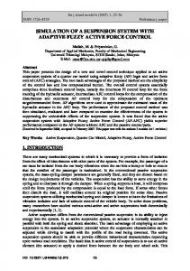
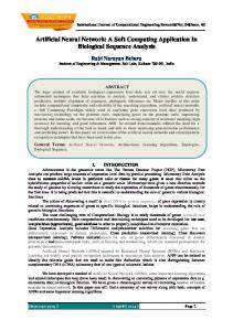
2. ACTIVE SUSPENSION MODEL The conventional passive quarter car suspension model can be graphically represented in Fig. 1a while a schematic of the active model counterpart can be seen in Fig. 1b. Note the presence of an additional actuator force that is deliberately incorporated into the active system. Generally, the quarter car is represented by a two degree of freedom (DOF) model and comprises a sprung mass (body of car) fully supported by a spring, damper and hydraulic actuator which are all attached to unsprung mass (tyre or wheel) at the other end.. zs sprung mass (body), ms
passive suspension
fa
bs ks
body (sprung mass)
zu unsprung mass (tyre), mu
tyre (unsprung mass)
kt zr
road terrain
(a)
(b)
road terrain
Figure 1: A quarter car representation of passive (a) and active (b) suspension model. 26
Mailah, Priyandoko: Simulation of a Suspension System with Adaptive Fuzzy Active Force ... The unsprung mass is assumed to have only the spring feature and is in contact with the road terrain at the other end. The road terrain serves as an external disturbance input to the system. Only vertical motion is assumed in the simulation study. The equations of motion for the active system are based on Newtonian mechanics and given as [5]: ms&z&s = −ks (zs − zu ) − bs (z&s − z&u ) + fa mu&z&u = ks (zs − zu ) + bs (z&s − z&u ) − kt (zu − zr ) − fa
where ms and mu bs ks and kt zs and zu zr zs–zu and zu – zr z& s and z&u &z&s and &z&u fa
: : : : : : :
sprung mass and unsprung mass respectively damping coefficient stiffness of spring and tyre respectively displacement of sprung mass and unsprung mass respectively displacement of road deflection of suspension and tyre respectively velocity of sprung mass and unsprung mass respectively
: :
acceleration of sprung mass and unsprung mass respectively actuator force
(1)
It is assumed that the suspension spring stiffness and tyre stiffness are linear in their operation ranges and the tyre does not leave the ground. The displacements of both the body and tyre can be measured from the static equilibrium point.
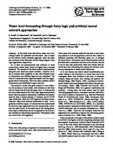
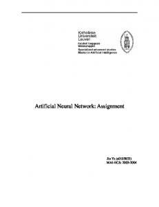
3. HYDRAULIC ACTUATOR MODEL A schematic diagram of a translational double acting hydraulic actuator driven by a three-land four-way spool valve is depicted in Fig. 2. An actuator is placed between the sprung and unsprung masses and can exert a force fa in between ms and mu. The hydraulic actuator consists of a spool valve (servo valve) and a hydraulic cylinder. ps and pr are the supply and return pressures going into and out of the spool valve, respectively, xv is the spool valve position, pu and pL are the oil pressures in the upper and lower cylinder chambers respectively and xw-xc is the hydraulic piston displacement. Hydraulic cylinder
xv
xc pr
Qu
pu
ps
pr
QL
pL
Spool valve xw
Figure 2: Double acting hydraulic actuator. The actuator works as follows. As the spool valve move upward (positive xv), the cylinder upper chamber is connected to the supply line ps and its pressure increases. At the same time, the lower chamber is connected to the return line pr and its pressure decreases. The pressure difference then make the hydraulic cylinder extend or compress. The differential equation governing the dynamics of the actuator is given in [11, 12] as follows: 27
Mailah, Priyandoko: Simulation of a Suspension System with Adaptive Fuzzy Active Force ... Vt p& L = QL − Ctm pL − A( z&s − z& u ) 4β
(2)
where fa, Vt, β , A, Ctm are force, total actuator volume, effective bulk modulus, actuator ram area and coefficient of total leakage due to pressure, respectively. Note that the actuated force, fa could be easily computed using the general equation:
f a = pL A
(3)
where fa is the general force, pL is the pressure and A is the cross sectional area of the cylinder (pipe). Using the equation for hydraulic fluid flow through an orifice, the relationship between spool valve displacement xv and the total flow QL is given by: p s − sgn( xv ) p L
QL = C d wx v
(4)
ρ
where Cd and w are the discharge coefficient and spool valve area gradient respectively. The spool valve displacement xv can be related to the input current iv through the following linear dynamic equation: 1 (5) x& v = (− x v + k v iv ) τ where kv is the valve gain and τ is time constant of the servo valve.
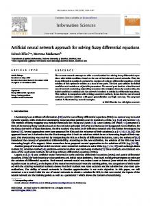
4. ADAPTIVE FUZZY SCHEME Most fuzzy logic controllers developed till now have been of the rule-based type, where the rules in the controller attempt to model the operator’s response to particular process situations. Conventional fuzzy logic control involves four components or operations method for fuzzification, membership function, method for fuzzy inference and method for defuzzification [10]. Following Wang [13], an adaptive fuzzy logic network model adopting a Takagi-Sugeno configuration is briefly introduced in this section. It incorporates a backpropagation learning method typically used in a neural network configuration. The adaptive fuzzy system is shown in Fig. 3. In this network, the structure will be determined during the initialisation stage and all fuzzy membership functions are connected to form completed rules. The network uses a product inference engine, singleton fuzzifier, centre average defuzzifier, and Gaussian membership function: ⎡
2 ⎞⎤ ⎛ ⎛ ⎜ ⎜ xi − xil ⎞⎟ ⎟⎥ N l a exp⎜ − ⎟⎥ i =1 i ⎜ ⎜⎝ σ il ⎟⎠ ⎟⎥ ⎠⎦ ⎝
M l⎢ y l =1 ⎢
∑
∏
⎢⎣
f ( x) =
⎡
M ⎢ l =1 ⎢
∑
⎛ ⎛ ⎜ ⎜ xi − xil N l a exp ⎜− ⎜ i i =1 ⎜ ⎝ σ il
∏
⎢⎣
⎝
⎞ ⎟ ⎟ ⎠
(6)
2 ⎞⎤
⎟⎥ ⎟⎥ ⎟⎥ ⎠⎦
where xi is input to the fuzzy network, i =1,..., n (n is number of inputs) and l=1,..., M (M is the number of rules and it will be determined during the initialisation stage and will be fixed during learning stage). The parameter y l is the centre of l-th consequent fuzzy set and xil and σ il are centre and width of Gaussian antecedent membership functions at rule l and input i, respectively. 28
Mailah, Priyandoko: Simulation of a Suspension System with Adaptive Fuzzy Active Force ...
Figure 3: An adaptive fuzzy scheme. By assuming a il =1, the error system can be expressed as: e p = v( x) =
{
}
2 1 f desired ( x p ) − f actual ( x p ) 2
(7)
The update of x is given by: x(k + 1) = x(k ) + Δx Δx = −α
∂e P ∂x
(8) k
where α is the learning rate. In order to minimise v(x) in equation 7 with respect to the parameter x, the updates of the parameters y l , x il , σ il are defined as: ( f − d) l y l (k + 1) = y l (k ) − α z b
xil (k + 1) = xil (k ) − α
(
(9)
)
( f − d) l 2( xi − xil (k )) y (k ) − f z l b xil (k )2
(f σil (k +1) = σil (k) −α
(
(10)
)
l 2 − d) l l 2(xi − xi (k)) y (k) − f z b xil (k)3
(11)
and: f = f actual ( x ) , d = f desired ( x ) , z = ∏ P
a=∑
P
l
2⎞ ⎛ ⎛ ⎜ ⎜ x i − x il ⎞⎟ ⎟ , N exp ⎜ − ⎟ i =1 ⎜ ⎜⎝ σ il ⎟⎠ ⎟
⎝
( ) ( )
⎠
M yl zl l =1 M zl l =1
b=∑
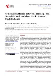
5. ACTIVE FORCE CONTROL Active force control (AFC) strategy was first proposed by Hewit and co-workers to control a dynamic system in order to ensure the system remain stable and robust in the presence of 29
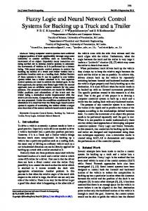
Mailah, Priyandoko: Simulation of a Suspension System with Adaptive Fuzzy Active Force ... known and unknown disturbances [14, 15]. AFC has been demonstrated to be superior compared to conventional methods in controlling a robot arm [16, 17]. Fig. 4 illustrates the application of AFC concept to a translational system. Disturbances Desired position xd +
Controller e
Gc
-
Q
Actuator +
Ga
Suspension system
+
fa +
Actual position
a
G
1 s2
x
+ Force sensor
Accelerometer a' Estimated mass
H Active Force Control
Measured force
f a'
+
Measured acceleration
M'
Q'
Figure 4: A schematic diagram of an AFC strategy. From Fig. 4, the estimated variable Q’ is passed through a function H, before subtraction from a command vector at the summing junction. A suitable choice of H can cause the output x to be made invariant with respect to the disturbance Q. A suitable set of control loop is applied to the above open loop system, by first generating the world coordinate error vector, e = (xd - x) which would then be processed through a controller function, Gc (typically a classic PD controller). Thus, the system is reduced to a set of non-interacting loops. An outer positional loop is formed through the world coordinate error vector, e. The main computational burden in AFC is the multiplication of the estimated inertia matrix with the acceleration of the translational dynamic system before being fed into the AFC feed forward loop. The fundamental principle of AFC is to use some measured and estimated values of the identified system parameters, namely the measured force and acceleration of the dynamic system and the estimated mass of the system. The basic AFC equation can then be written as follows [15]: Q’ = fa’ – m’a’
(12)
where the superscript (’) denotes the measured or estimated values of the parameters. The measurable physical quantities of the system are the actuating force (fa’) and the acceleration (a’). These can be readily and practically measured using force and acceleration sensors, respectively. The estimated mass (m’) of the system should be estimated appropriately using a suitable method such as crude approximation or intelligent techniques [14-17]. If all the parameters are successfully acquired, then the resulting estimated force (Q’) from equation 12 should result in a very robust and stable performance of the control system once this signal is fed back to the AFC control loop. It is immediately obvious that the control algorithm used here is very simple and has huge practical implication due to the fact that the computational burden is very minimal and that it could be readily implemented in real-time without any fuss as demonstrated in [15].
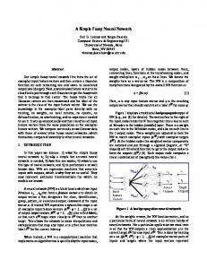
6. DESIGN OF PROPOSED AF-AFC SCHEME The complete AF-AFC scheme is shown in Fig. 5. Note the three loops that are contained in the overall proposed control system and that two AF systems were used, namely AF1 for the 30
Mailah, Priyandoko: Simulation of a Suspension System with Adaptive Fuzzy Active Force ... outer loop positional control and AF2 for computing the estimated mass necessary in the AFC section. Hydraulic Actuator
e
(zs-zu)d +
AF1
-
+
+
PI +
Q +
fa +
Ga
a
Suspension system
1 s
1 s
(zs-zu)
-
a'
AFC
d/dt
H
AF2 fa '
-
+
M'
Q'
Figure 5: A block diagram of the proposed AF-AFC scheme. The disturbances (Q) used in the study are modelled as a step function with a constant height of 6 cm and a sinusoidal function with an amplitude of 5 cm and frequency 3 Hz. They are deliberately introduced to test the system robustness or its capability to yield favourable results even in the presence of the disturbances. The design of the control problem was carried out according to the following three-steps procedure: 1. The inner loop controller for force tracking hydraulic actuator commands was first designed. The majority of the existing literature assumes that the commanded force can be achieved accurately and frequently done without considering actuator dynamics. However, they are highly non-linear and their force generation capability is closely coupled with the vehicle body motion. When a less capable actuator is used, the sub-loop design first needs to be carried out [10, 11]. Force tracking of the hydraulic actuator commands in this simulation is accomplished using a PI controller, with the proportional gain Kp and integral gain Ki set to 1 and 0.5 respectively, based on Ziegler-Nichols method for the purpose of simulation. The validation of the force tracking capability is done considering sinusoidal, square wave and saw tooth input forcing functions. In Laplace domain, the resulting PI controller will have the following expression:
Gc = K p +
Ki s
(13)
2. The outer loop controller (AF1) was designed to satisfy performance requirements using Takagi-Sugeno AF model. The training algorithm used for AF is a back-propagation real time learning method (equation 8). The input and output universes of discourse of the fuzzy controller are normalized in the range [-1,1]. Two inputs of the AF1 controller are error e and change of error de. These two inputs are scaled by two gain coefficients Ke and Kde respectively, in order to normalize these inputs in the range [-1,1]. The output is the force ranging from -2000 to 2000 N and is considered a singleton value scaled by K01 normalized in the range [-1,1]. Note that the numerical scale Ke, Kde and K01 were acquired prior to simulation based on human experience and also results from previous studies that employs conventional methods (an example can be found in [12]). Fig. 6 shows a representation of the membership functions for respective parameters noting that N denotes ‘negative’, Z is ‘zero’ and P is ‘positive’.
31
Mailah, Priyandoko: Simulation of a Suspension System with Adaptive Fuzzy Active Force ...
Figure 6: Membership functions for the input/output parameters of AF1. 3. The AFC loop was specifically designed to compensate for the dynamic disturbances. The AFC scheme has two inputs, namely the actuated force from the hydraulic actuator and body acceleration components. The estimation of the mass needed by AFC loop is the vital element that contributes to the effectiveness of the control scheme. In this simulation, the estimated mass was acquired using the AF strategy. Note that the AF2 used here is fully independent of the AF1 employed for the outer loop control. Training algorithm for the AF2 uses a back-propagation real time learning method as defined by equation 8. Two inputs of the AF2 controller are the sprung mass acceleration and suspension deflection. These two inputs are scaled by two coefficients Ksa and Ksd respectively that are normalized in the range [-1, 1]. The output is a singleton value of estimated mass in the range 0 to 100 kg and is again scaled by K02 normalized in the range [-1, 1].
7. SIMULATION The parameters of the quarter car model and hydraulic actuator are obtained from [11, 12] and listed as follows: ms = 290 kg β = 1.00 kv = 0.0157 m/A 12 5 mu = 59 kg α = 4.515e N/m τ = 0.0046 sec ks = 16,812 N/m γ = 1.545e9 N/(m5/2 kg1/2) bs = 1,000 N/m/sec Ps = 1500 Psi (10342500 Pa) ku = 190,000 N/m A = 3.35e-4 m2 Simulation was performed using MATLAB and Simulink. The Simulink diagram of the AF-AFC strategy for the active suspension system is shown in Fig. 7. It consists of the hydraulic double acting actuator model and its PI controller, suspension system dynamic model, AF1 controller, AFC controller (with AF2), disturbances and reference input of the system. The system dynamic has two inputs which are the road disturbance and actuator force from hydraulic actuator. It also has four outputs which are the body displacement, suspension deflection, tyre deflection and body acceleration which serve as the main parameters of interest or responses to be analysed and evaluated for the dynamic performance of the suspension system. Simulation is performed using the parameters and conditions as described in the earlier part of this section. Three types of control systems are compared and evaluated, namely the open loop passive, AF and AF-AFC schemes. All the relevant parameters and conditions are maintained the same for all the schemes to ensure a realistic and fair one-to-one comparison.
8. RESULTS AND DISCUSSION The results of the force tracking capability of the hydraulic actuator employing PI controller are shown in Fig. 8. It is obvious that the actual forces from the actuator represented by a series of dotted lines for all the input functions can readily track the desired forces (solid lines). The actuator is thus deemed suitable to be implemented into the overall proposed control scheme. 32
Mailah, Priyandoko: Simulation of a Suspension System with Adaptive Fuzzy Active Force ...
Figure 7: Simulink diagram of an AF-AFC strategy.
Figure 8: Force tracking of the hydraulic actuator with (a) sinusoidal, (b) square wave and (c) saw-tooth inputs. Fig. 9 shows the variation of the estimated masses computed by the AF2 component in the AFC loop upon simulation using step and sinusoidal road profiles as the input disturbances to the control system. In Fig. 9a, the mass parameter shows high initial value and later stabilises to almost a constant value towards the end of the simulation period for the step input road profile indicating that it assumes the characteristic of the applied force. Likewise, a similar trend can be seen in Fig. 9b for the sinusoidal disturbance where the computed estimated mass fluctuates about the mid value 50 kg. These masses are the important parameters that need to be used by the system to trigger the AFC control action. Figs. 10 show further responses of the system with step function disturbance. Fig. 10a shows the curve for sprung mass displacement for all the three schemes while Fig. 10b shows the suspension deflection. The AF-AFC did an excellent job in reducing the sprung mass displacement and suspension deflection than AF controller and passive suspension systems. Fig. 10c illustrates the trend in the sprung mass acceleration while Fig. 10d exhibits the tyre deflection. It is generally considered an enhancement in system performance in terms of vehicle riding comfort if all the curves show reduction in the amplitudes.
Figure 9: Estimated masses in the AFC loop for the different input conditions. 33
Mailah, Priyandoko: Simulation of a Suspension System with Adaptive Fuzzy Active Force ...
Figure 10: Sprung mass displacement (a) and suspension deflection (b), sprung mass acceleration (c) and tyre deflection for the step input road profile (d). Figs. 11a to 11d show the responses of system with sinusoidal disturbance. Similar to the step input disturbance, the performance of the system clearly indicates the superiority of the AF-AFC scheme over its counterparts in accommodating the introduced conditions. The magnitude of compensation is much greater than that of the step input. This further reaffirms the robustness and effectiveness of the proposed scheme in controlling the vertical motion of the suspension system. Thus, it is expected that the new scheme could greatly contribute to the improvement of the vehicle riding comfort performance.
Figure 11: Sprung mass displacement (a) and suspension deflection (b), sprung mass acceleration (c) and tyre deflection for the sinusoidal road profile (d). 34
Mailah, Priyandoko: Simulation of a Suspension System with Adaptive Fuzzy Active Force ...
9. CONCLUSION A new and novel AF-AFC scheme has been designed and developed to control an active suspension incorporating a non-linear hydraulic actuator of a quarter car model. The performance of the proposed control method is found to be significantly superior compared to the other systems considered in the study with the given loading and operating conditions. This could provide useful indication in terms of the ability of the system to suppress the undesirable effects and may in turn lead to positive enhancement with respect to vehicle riding comfort. A number of different loading and operating conditions can be further investigated particularly focusing on the undesirable vibration effects. An on-going project via the development of a full working prototype is underway to practically verify and validate the simulation trends of the parameters of interest.
10. ACKNOWLEDGEMENTS The authors would like to thank the Malaysian Ministry of Science, Technology and Innovation (MOSTI) and Universiti Teknologi Malaysia (UTM) for their continuous support in the research work. This research was fully supported by an IRPA grant (No. 03-02-060123EA001).
REFERENCES [1] Cherry, A. S.; Jones, R. P. (1995). Fuzzy logic control of an automotive suspension system, IEE Proceedings of Control Theory Application, Vol. 142, No. 2, 149-160 [2] Appleyard, M.; Wellstead, P. E. (1995). Active suspension: some background, IEE Proceedings of Control Theory Application, Vol. 142, No. 2, 123-128 [3] D’Amato, F. J.; Viassolo, D. E. (2000). Fuzzy control for active suspensions, Mechatronics, Vol. 10, 897-920 [4] Taghirad, H. D.; Esmailzadeh, E. (1998). Automobile passenger comfort assured through LQG/LQR active suspension, Journal of Vibration and Control, Vol. 4, No. 5, 603-618 [5] Nguyen, T. T.; Bui, T. H.; Tran, T. P.; Kim, S. B. (2001). A hybrid control of active suspension system using H∞ and non-linear adaptive controls, Proceedings of ISEI 2001, Vol. 2, 839-844 [6] Joo, D. S.; Al-Holou, N.; Weaver, J. M.; Lahdhiri, T.; Al-Abbas, F. (2000). Nonlinear modeling of vehicle suspension system, Proceedings of the American Control Conference, Vol. 1, No. 6, 115-119 [7] Chen, H. Y.; Huang, H. J. (2005). Adaptive sliding controller for active suspension system, Proceedings of International Conference on Control and Automation, Vol. 1, 282-287 [8] Sun, J.; Yang, Q. (2005). Self-adjustment fuzzy control of automobile active suspension, Proceedings of IEEE Intelligent Vehicles Symposium, 354-357 [9] Mock, J. R.; Weeks, D. A.; Beno, J. H.; Nichols, S. P.; Bresie, D. A.; Guenin, A. M. (2002). Dual purpose fuzzy logic controller for an active suspension system, SAE 2002 World Congress, Detroit, Michigan [10] Babuška, R. (2002). Neuro-fuzzy methods for modelling and identification, Abraham, A.; Jain, L. C.; Kacprzyk, J. (Editors), Recent Adv.Int. Paradigms and App, Springer-Verlag, Heidelberg, 161-186 [11] Merritt, H. E. (1967). Hydraulic Control Systems, John Wiley & Sons, Inc., New York, NY [12] Chantranuwathana, S.; Peng, H. (2004). Adaptive robust force control for vehicle active suspensions, International Journal of Adaptive Control and Signal Processing, Vol. 18, 83-102 [13] Wang, L-X. (1994). Adaptive Fuzzy Systems and Control, Prentice Hall, Englewood Cliffs, NJ [14] Hewit, J. R.; Morris, J. R. (1999). Disturbance observer control with estimation of the inertia matrix, Proc. of IEEE/ASME International Conference on Advanced Intelligent Mechatronics, 753-757
35
Mailah, Priyandoko: Simulation of a Suspension System with Adaptive Fuzzy Active Force ... [15] Mailah, M. (1998). Intelligent Active Force Control of A Rigid Robot Arm Using Neural Network and Iterative Learning Algorithms, PhD Thesis, University of Dundee, UK [16] Hussein, S. B.; Zalzala, A. M. S.; Jamaluddin, H.; Mailah, M. (2000). An evolutionary neural network controller for intelligent active force control, Evolutionary Design and Manufacture, Parmee, I. C. (Editor), Springer Verlag, London, 352-362 [17] Mailah, M.; Rahim, N. I. A. (2000). Intelligent active force control of a robot arm using fuzzy logic, Proc of IEEE International Conference on Intelligent Systems and Tech. TENCON 2000, 291-296
36