Stag&: The transmission lines are restored at t=l.4sec. Stages: Another fault occurs at ~ 2 . l s e c . Stage6: The fault is removed by opening the breakers of the.
IEEE SMC Workshop on Soft Computing in Industrial Applications - 2003
FUZZY LOGIC CONTROLLERS -AN APPLICATION TO POWER SYSTEMS N. YADAIAH' I.*
J.L.BHATTACHARYA3
CH. V.S.R.K. BABU2
Department of Elcctrical & Electronics Engineering College of Engineering, Jawaharlal Nehru Technological University, Kukatpally, HYDERABAD - 500 072 Andhra Pradesh, INDIA. vadaiahn(~horniail.coin
Abszracr :-This paper presents design of a fumy controller to prevent an electric power system loosing synchronism after a large sudden fault and to achieve good postfault voltage level. The developed Fuzzy logic controller (FLC) accepts speed deviation and acceleration as inputs and generates the control signal. The simulation study is carried out based on a single machine infinite bus power system. The performance of this controller is compared with a nonlinear state feedback linearizing controller (NFLC).
Key words: Fuzzy logic, feedback controller, power system stability. I
Bharat Heavy Elecmcals Limited, 'Corporate Research & Development Division, Vikas Nagar, HYDERABAD - 500 093 Andhra Pradesh, INDIA. javanlkr bhclrnd.co.in
severe disturbances. The developed Fuzzy logic controller accepts speed deviation and acceleration as controller inputs. These input signals are first characterized by linguistic variables using Fuzzy set notations. Then, a decision table is developed relating controller inputs and output of the controller. A set of logical operation is performed using controller inputs and decision table to get the desired controller output. The performance of this controller is compared with a nonlinear state feedback linearizing controller (NFLC).
INTRODUCTION
This paper considcrs thc problem of transient stability and voltage regulation in power system. A large disturbancc on powcr system occurring near the generator causes vast changes in the load angle, power transfer and the generator voltage, which may cause machine to fall out of step. This category of stability is known as transient stability, which is a fast phenomenon occumng within a span of few seconds. The purpose of implementing stability controllers in power system is to prevent such instances of a generator losing synchronism after a large disturbance. The generator model in a power system essentially offers a nonlinear problem, however controller design using linear control system theory and linearized model around an operating point has been studied widely [I], [ 2 ] .But in case of large disturbances these linearized control techniques are not effective. Consequently nonlinear feedback linearizing controllers (NFLC) are implemented [2]. These nonlinear methods provide better performance than the linear control techniques. However, the voltage deviation occumng in the post-fault duration with the NFLC is of concern. In this study an attempt is made to take care of both transient stability and voltage regulation problem in the post-fault duration using Fuzzy Logic Controller (FLC). Jiang, Wu, Zhang and Zhou [2] have proposed a novel robust observerbased nonlinear control of multimachinc powcr systems. Guo, Hill and Wang [3] havc prcsentcd a global control for global transient stability and voltage regulation for power systems. In this work an improved excitation controller for a synchronous generator is developed based on Fuzzy set theory to maintain transient stability and achieve post fault voltage regulation of a power system when subjected to
11.
DYNAMIC MODEL OF POWER SYSTEMS
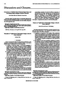
In the present paper, we consider a single machine infinite bus power system configuration. The singlc machine infinite bus system exhibits important characteristics of multi-machine system and is relativcly simple to study, analyze and it helps to bring out the performance advantage of a FLC. A single machine infinite bus powcr systcm arrangement shown in Fig.] is considcrcd.
Fig.1 Asingle machine intinite bus power system
The classical third-order dynamical model of a single machine infinite bus power system shown in Fig.] can be written as follows [3] ; Mechanical equations:
6 = 0-0,
(1)
0-7803-7855-5/03/$17.00 0 2003 IEEE
1
.
the controller output from the measured system variables
Generator Electrical Llywmics
*
1
E ‘ , =-(E,
0 and 0 ,the follo\;ing procedure is used.
-E,)
T do
(3)
Stepl: Measuring input limits of fuay system: With previous experience, the ranges of speed deviation in
.
Electrical equations:
p.u is 0=[LN .. LP] and the acceleration in p.u. is 0=[LN ..LP] are determined.
VSE, P,= -sin
S
Xds
VS I , = -sin6 xds
e
=xad I ,
Q , = - - Ev*, C O S 6 - xds
(5)
5’
(7)
xds
E, = X a d , E , = kp, v, = 1 -[Xs2Eq2 +VS2Xd2+ 2 X , X d X , P ,
Step2: Developing the membership functions: The ranges of two variables are decomposed into five sets of fuzzy regions using linguistic variables LN (large negative), MN (medium negative), VS (very small), MP (medium positive), LP (large positive). Based on the expertise, these linguistic variables are defined for the speed deviation, acceleration and output of fuzzy system
cot6 11’2
(10)
Xds
The variables and other parameters descriptions are given in appendix and for more details the readers suggested to refer [11,[31,[41.
Step3: Developing decision table: The decision table is developed using the following concept. When a fault occurs in the power system for a short time, the transient stability of the machine is subjected to a large impact, which causes significant reduction in the machine terminal voltage, speed deviation and acceleration. But under steady state conditions the speed deviation and acceleration are zero. In order to bring these to original state the above deviations are used as inputs to the fuzzy logic controller. Based on previous experience, the decision table is prepared. A five member fuzzy system consists of 25 entries denoting each entry for
III. DESIGN OF STATE FEEDBACK LlN?2ARIZING CONTROLLER
The dynamic model of multimachine power system and the design of decoupled state feedback linearizing controller has been proposed by Jiang, Wu, Zhang and Zhou [2]. In this, we consider a single machine power system and the corresponding state feedbacklinearizing controller is described by the following relations
v = -a,(S
-&) - a2(w- W O )- a,w
’
one rule. For example, Rule I : If 0 is LP and 0 is LN then the output of fuzzy system would be VS. Similarly other rules are formed and are shown in Table I. Table. I. Decision Table
(11)
U=
where aj , j=1,2,3 are feedback gains and they can be determined by linear optimal control strategy.
I
I
I
I
I
I
I
IV. DESIGN OF FUZZY LOGIC CONTROLLER
We have considered the two inputs and single output fuzzy system for the design of controller. It accepts the speed deviation and acceleration as its inputs. It generates control signal, which is an excitation to the generator. During disturbance condition, dynamic performance of system could be evaluated by examining the response curves of speed deviation ( 0 )and acceleration (0).To determine
2
The defuzzification of control signal is obtained by using the “center gravity” concept [5]. The output of the FLC is applied to the generator excitation and its schematic representation is shown in Fig. 2.
.
5. LP is 0.01 I 0 5 1.0 The output regions of the fuzzy logic controller is defined
as:
+.
SpssddWihl
1
2
-
z&x4hwim
Fig. 2 Schematic representationof generator excitation
The relation between the controller output and the excitation is as follows.
.
where U is the output of FLC. V. SIMULATION RESULTS
The systems parameters of the single machine infinite bus power systems considered in this work are as follows: q = 1.863, ~ ' ~ 4 . 2 5 xT= 7 , 0.127, Tdo'= 6.9, xl= 0.4853, H4,D=5, &=l, x a = 1.712 ,%= 314.159, X , = 0.6580 . The physical limit of the excitation voltage is taken as
-3Iku
c f
16.
The operating point of the power system used in the simulations is 6 ~ 7 2 9P,0=0.9 P.u., V, = 1.0 pa.. With previous experience we have considered the ranges for speed deviation is [-1.5 1.51, acceleration is [-1.0 1.01 and the logic controller is taken between output range of the ~~IZZY 0.12 to 0.12. Now we define the membership function of each variable as: The regions of membership functions for speed deviation are: 1.LN is -1.50 I 0 I-0.225 2. MN is -0.40 10 I -0.05 3.VS is -0.10 I 0 I 0.10 4. MP is 0.050 I0 10.40 5. LP is 0.225 10 5 1.50 For acceleration the regions are taken as 1.LNis -1.0
.
5 0 5-0.01
.
2. MN is -0.395 5 0 5 -0.005 3. vs is -0.02 I 0 I 0.02
4. MP is 0.005 I0 10.395
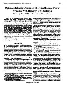
1. LN is -0.12 I U I-0.01 125 2. MN is -0.02 Iu I -0.0025 3. VS is -0.005 S U I 0.005 4. MP is 0.0025 IU 20.02 5. LP is 0.01 125 I U 5 0.12 By using these membership h c t i o n s the decision table rules are implemented and the fuzzy control signal has been generated. Let us consider the following cases to simulate the proposed method . Case 1Permanentfault: Stage 1:The system is in pre-fault steady state. Stage 2: A fault occurs at G0.1 sec. The-fault location is indexed by a positive constant which is the fraction of line to the left of the fault. In this case 2 =0.035. Stage 3: The fault is removed by opening the breakers of the faulted line at ~ 0 . 2 sec. 5 Stage 4: The system is in post-fault state. The simulation results are shown in Fig. 3. Case 2 . Pennanent-fault +increase of the Mechanical input power: Stage1: The system is in pre-fault steady state. Stage2: A fault occurs at H.lsec. Stage3: The fault is removed by opening the breakers of the faulted line at H.25sec. Stage4: The Mechanical input power of the generator is increased by a step of 30% at ~ l s e c . Stages: The system is in a post-fault state. For this case 2 4.34. The simulation results are shown in Fig. 4. Case 3. Temporaryfault -+ Permanentfault: Stage1: The system is in pre-fault steady state. Stage2: A fault occurs at t=O.lsec. Stage3: The fault is removed by opening the breakers of the faulted line at ~0.25sec Stag&: The transmission lines are restored at t=l.4sec. Stages: Another fault occurs at ~ 2 . l s e c . Stage6: The fault is removed by opening the breakers of the faulted line at G 2 . 2 5 ~ ~ . Stage7: The system is in post-fault state. For this case 2=0.155. The simulation results are shown in Fig. 5.
3
1-
Dalta(NF LC) 160 $60
I
4n
A
1
z f
U
G
60
0
LO
D elta(F L C )
160 160 1 a0
I
100 80
60 60
20
0
2
L
6
8
1
0
l t n t (8 e c 3
I
I
Tarminrl Voltago(FLC)
J
I
Field Excaation(NF LC)
Field Excitrtion(FLC)
I
I
t J TtnDI(aeC)
I
I T D e (see.)
-LJ
Fig.3. Power system response for case 1. DotlapFLC) 160
Delta(FLC)
~
140 120
e
100
an 60
5
60 20
0 2
0
IO
8
6
4
0
Tim e ( r e o ) ~~
~
~~
Terminal Vohage(N F LC)
< .4
I
. 0
4
. 2
. 1
.
6 TD R (Set.)
. 8
. 1
0
II
2
L 6 Tal t @ t c .)
I
8
Terminal VoHape(FLC) 197
1
Field Excitation(FLC)
Field Excitation(NFLC) 8
8
I
I
6 L A
n 2
Eo -2 -4
J
I
J
-L
I The(sec.)
Tirne(sec.)
-~ Delta(NFLC)
Delta(FLC)
160
I
P
2
L 6 Time(sec.)
S
B
10
Z
L
b
8
l
O
Tim e(s e c .)
Terminal Voltagc(FLC)
12,
F i e l d ExcitationCH F L C ) -
r
~
~~
~
F i e Id E x c itationff L C I
I
6
I
.6 L 2
0 -2
. .
I
I 1
1
6
8
1
I
Fig. 5 . Powa system response for case 3.
VI. CONCLUSION
A fuzzy logic controller has been developed to prevent an electric power system losing synchronism after a sudden fault and also to achieve good post-fault voltage regulation. The performance of the proposed controller is compared with existing nonlinear state feedback linearized controller. The simulation results shows that the FLC is able to maintain a good voltage regulation over NFLC in addition to maintaining the transient stability.
REFERENCES [I] P.M. Anderson and AA Fouad, Power systems control and stability, IEEE Press, 1994. [2] L. Jiang, Q.H. Wu, C. Zhang and X.X. Zhou, “Robust Observer-based Nonlinear Control of Multimachine Power Systems”, LEE Proc. Gener. T r a m . Distrib., Vol. 148, pp. 623-631,2001. [3] Y . Guo,D.J Hill andY. Wang, “Global Transient Stability and Voltage Regulation for Power Systems”, IEEE Trans. Power Systems, VoL 16, pp. 678-688,2001.
5
[4]Y.Wang, D.J. Hill, R.H. Middelton and L. Gao,"Transient stability enhancement and voltage reguIation of power systems", IEEE Trans. Power syszors, Vol. 8,pp 620-626,1993. [5] K. M. Passino and S.Yurkovich, 'Fumy Control', AddiSon-Wedey, 1998.
Appendix: 6(t) - Power angle of the generator (in radian) W ( t ) - Rotor speed in radsec Pm - mechanical input power (in P.u.) P, - active power delivered to the bus (ia pa.)
E; V, Qe
-
Transient EMF in the quadrature axis (in pa.) Terminal voltage (in P.u.) - Reactive power delivered to the bus (in P.u.)
x& = x d +xj" +X,j
xl
-
x&
=xd
XT
N. Yadaiab received B.E. in Electrical Engineering from college of Engineering, Osmania University, Hyderabad, India, in 1988, M. Tech. in Control systems from IIT Kharaggur, India in 1991 and Ph.D. in IZlectrical Engineering from Jawaharlal Nehru Technological University, Hyderabad, India in 2000. He received Young Scienlirt Fellowship (YSg of Andhra Pmd& State Council for Science and Technology, in 1999. He is currently associate profasor of Electrical Engineering at J. N. T. University. His main research interest includes Adaptive Control, Neural Networks, Fuzzy logic, Nonlinear Systems, and Process Control.
CH. V.S.R.K. Babu received B.E. in Electrical and Elecaonics Engineering &om Andha University, Visakhapamam, India in 2000 and M.Tech. m Information Technology in power Engineering, from Jawaharlal Nehru Technological University, ' Hyderabad, India in 2003.
Transformer reactance (in P.u.) Transmission line reactance (in P.u.)
JLBhattacharya received B.E. in Electrical Engineering from MAD,
+xT+x,
xd
- d-axis synchronous reactance (in P.u.)
xd
-
d-axis transient reactance (in P.u.)
X,
-
q-axis synchronous reactance (in P.u.)
xad
- Mutual reactance between excitation coil and stator
D H
-
coil. dampingconstant Inertiaconstant.
Bhopal in 1973, M.Tech from IIT Kanpur, India in 1976 and Ph.D &om Auckland University, New Zealand in 1988. He received Commonwealth Scholarship for doing Ph.D in New Zealand. He joined Jyoti Ltd. Baroda in 1976 where he worked in the R&D unit and dealt with dc machine and synchronous generator design, in 1980 he joined Bharat Heavy Electricals Ltd. Hyderabad, India, in the R&D unit and since then he has been working and presently in the capacity of Senior Deputy General Manager. His current research mterest includes electrical machine desi- power system, intelligent systems and superconducting generators.
***
6