IACSIT International Journal of Engineering and Technology, Vol. 6, No. 4, August 2014
Fuzzy Logic Reasoning System for Line Following Robot Umar Farooq, Muhammad Amar, Muhammad Usman Asad, Ghulam Abbas, and Athar Hanif
implemented with a low cost, readily available single chip AT89C52 microcontroller. The robot with the proposed controller is set to run on a track of varying degrees of turns and is found to follow the track smoothly. In the sections that follow, work already done related to current problem, fuzzy controller design, robot architecture, and finally results are presented.
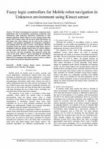
Abstract—This paper describes the design of fuzzy logic controller for a line following robot. The controller accepts inputs from two light sensors mounted underneath the robot and generates motion commands to keep the robot on track. The performance of the proposed controller is compared with simple on-off control and it is observed that fuzzy logic control is better choice owing to its smoothness in following the desired track and lesser amount of time taken in completing the track. The platform is ideal to study in real time the various fuzzy inference systems and hence can be utilized as laboratory course work for soft computing algorithms.
II. RELATED WORK
Index Terms—Line following, fuzzy logic control, on-off control.
I. INTRODUCTION The theme of many mobile robot competitions across the globe is to enable the robot to perform a certain task and reach the target by navigating using pre-defined strips in indoor environments. These line tracing robots simulate the behavior of robots in industry where they are used to transport goods within the industry using pre-defined path. Easy to construct and owing to have low cost, these line following robots are first choice to study control algorithms. The conventional control techniques utilize the mathematical model of robot to design a controller for robot. These controllers work well in environments for which they are designed and often fail in noisy environments that are difficult to model. The evolvement of soft computing methods provides another choice for designing robot controllers for complex environments without developing a mathematical model of the system [1]. Among the various techniques in this category, fuzzy logic offers a promising solution to handle environment uncertainties. Fuzzy inference system is a universal approximator and has ability to do non-linear mapping between the sensor values and control variables. This paper discusses the design of a fuzzy logic based controller for line following operation of a differentially steered mobile robot. The proposed controller is a single input, two output system and uses Mamdani system as inference mechanism. The input to the controller is the difference between two light sensors mounted undercarriage the robot and output forms the speed commands for left and right motors. The controller is designed in MATLAB and Manuscript received May 27, 2013; revised August 22, 2013. Umar Farooq and Muhammad Amar are with Department of Electrical Engineering, University of The Punjab Lahore (e-mail:
[email protected];
[email protected]). Muhammad Usman Asad, Ghulam Abbas, and Athar Hanif are with Department of Electrical Engineering, The University of Lahore (e-mail:
[email protected], ghulam.
[email protected]. Pk,
[email protected]).
DOI: 10.7763/IJET.2014.V6.705
244
The soft computing techniques especially fuzzy logic has been used by many researchers for line tracing in mobile robots. A microprocessor-based fuzzy logic controlled line following robot is described by Reuss and Lee [2]. The robot is based on the RCX LEGO Mindstorms which incorporates an on-board Hitachi H8 microprocessor. Two light sensors are used under the robot to sense a white line drawn on a black surface and a fuzzy logic algorithm is used to move the robot to follow the line. A fuzzy logic controlled miniature LEGO robot for undergraduate training is described by Azlan et al., [3]. This study is divided into two parts. In first part, an object sorter robot is built to perform pick and place task to load different colored objects on a fuzzy logic controlled line following robot which then carries the preloaded objects to a goal by following the white line. In second part, fuzzy logic controlled light searching robot with the capability to navigate in a maze is developed. Harisha et al., [4] describes the design of a fuzzy logic reasoning system to control a mobile robot on predefined strip path with obstacles. The path guiding robot equipped with two IR sensors for line following and one IR proximity sensor for hurdle detection on path is able to navigate along strips with different speeds and stops when vehicle approaches to obstacle. A low cost educational microcontroller based tool for fuzzy logic controlled line following robot is described by Ibrahim and Alshanableh [5] which is used in the second year of undergraduate teaching in an elective course in the department of computer engineering of the Near East University. The robot is named as Robo-PICA and is equipped with a pair of infrared reflectors mounted at the bottom and at both corners of the robot. The designed fuzzy logic controller implemented inside PIC16F887 microcontroller using mikroC development environment keeps the robot on track. Another interesting paper on fuzzy logic and robot control is by Pawlikowski [6] where the development of a fuzzy logic speed and steering control system for an autonomous vehicle is described. Using an integrated vision system, the vehicle senses position relative to the angle of a line drawn on the ground, and processes that information through a fuzzy logic algorithm. The algorithm selects drive speeds for two independent motors, thereby providing the ability to go forward, or turn left or right while following a path.
IACSIT International Journal of Engineering and Technology, Vol. 6, No. 4, August 2014
III. FUZZY CONTROLLER DESIGN A single input, two output fuzzy logic controller (FLC) is designed for tracking white reflective line on blue background. The difference of color information from left and right sensor sensors forms the input to fuzzy controller while two outputs from the controller are pulse width modulated signals to control left and right motor speeds. MATLAB® Fuzzy Logic Toolbox is used to aid in FLC design. The toolbox contains functions, graphical user interfaces and data structures that allow the user to quickly design, test, simulate and modify a fuzzy inference system [7]. The steps involved in fuzzy controller design are described in this section: A. Fuzzification The input to FLC i.e., the difference value, DS, between the two sensors namely left and a right sensor is described by four fuzzy sets: LND, SND, SPD and LPD, the universe of discourse being from -50 to +50. The description of these fuzzy sets is shown in Table I.
LND SND SPD LPD
Description The difference between sensors has a large negative value The difference between sensors has a small negative value The difference between sensors has a small positive value The difference between sensors has a large positive value
2d s , 0,
DS , SND
1.8d s 90, 100, 100,
DS , SPD
1.8d s 91, 0,
DS , LPD
2 d s ,
-50 d s 0 0 d s 50 -50 d s 5 5 d s 50 -50 d s 5 -5 d s 50 -50 d s 0 0 d s 50
Fuzzy Set
Description
SLOW
Speed of left/right motor is slow
FAST
Speed of left/right motor is high
LM ,SLOW lm 100,
0 lm 100
(5)
LM , FAST lm ,
0 lm 100
(6)
B. Fuzzy Rule Base Four rules are designed for controlling robot motion while following the line. Of these rules, only two are fired at any instant. These rules establish the relation between sensor values and motor speeds in terms of linguistic values. A control curve is then plotted to visualize the variation in motor speeds given the sensor values. The rule base is shown in Table III while control curves for left and right motors are shown in Fig. 3.
The membership functions for DS, as shown in Fig. 1, are described by the expressions:
DS , LND
TABLE II: FUZZY SETS DEFINED FOR OUTPUT
The membership functions for LM/RM, as shown in Fig. 2, are described by the expressions:
TABLE I: FUZZY SETS DEFINED FOR INPUT Fuzzy Set
variable is scaled in range [0,100] to prevent floating point storage and calculations. Also, triangular membership function (MF) is used for all fuzzy sets because of limited computational resources of microcontroller. The outputs of FLC i.e., left motor (LM) and right motor (RM) speeds are described by two fuzzy sets: Slow and Fast; the universe of discourse being from zero (minimum) to hundred (maximum) which describes the duty cycle of PWM signal. The description of these sets is shown in Table II.
(1)
TABLE III: FUZZY RULE BASE FOR LINE FOLLOWING ROBOT Rule No.
(2)
(3)
Rule Description
I
IF DS is SPD THEN RM is FAST
II
IF DS is LPD THEN RM is SLOW
III
IF DS is SND THEN LM is FAST
IV
IF DS is LND THEN LM is SLOW
Rule I describe the situation when the robot gets deviated from the track slightly towards left. In this case, robot will continue to go at full speed until membership of LPD becomes larger than SPD. Rule II describe the situation when the robot gets deviated from the track largely towards left. In this case, membership of LPD is high and controller reduces the speed of right motor by a larger extent to keep it on track. Rules III and IV control the speed of left motor in the same manner as rules I and II control the speed of right motor.
(4)
C. Fuzzy Implication Fuzzy implication helps to evaluate the consequent part of each rule. Among the various implication methods available in literature, Mamdani implication method is selected. After the inputs have been fuzzified and FLC know the degree to which each part of the antecedent of a rule has been satisfied, degree of fulfillment of (DOF) of each rule is calculated using
Fig. 1. Input (DS) membership function
In these expressions, degree of belongingness of linguistic 245
IACSIT International Journal of Engineering and Technology, Vol. 6, No. 4, August 2014
AND operator. The output membership function is then truncated at DOF level. All the rules are evaluated in this manner and final output membership functions are aggregated in a cumulative manner using OR operator to yield the final fuzzy output. An example of the implication process is shown in Fig. 4 where the difference in sensor readings has a negative value. This situation corresponds to robot deviation towards right. At this value, the degree of membership of SND is high for left motor as compared to LND which results in reducing the speed of left motor not to a larger extent to keep the robot on track while speed of right motor is high owing to the maximum degree of membership of SPD and zero degree of membership of LPD.
aggregated output membership function and Z o is the crisp value which describes the duty cycle of PWM signal for controlling the speed of motors. n
Zo
Z i out ( Z i )
i 1 n
out ( Z i )
(7)
i 1
Fig. 2. Output (LM/RM) membership function Fig. 4. Fuzzy implication and defuzzification process
IV. ROBOT ARCHITECTURE The experimental prototype is a rectangular shaped differentially steered mobile robot. Two dc motors independently control two wheels on a common axis. Two caster wheels are provided for support. Two light sensors, each consisting of a pair of an LED and LDR, comprise the sensory system of the robot. A microcontroller board incorporating ADC0808 A/D and AT89C52 microcontroller is designed to run fuzzy controller(s). To drive the dc motors from microcontroller, a motor interface board is designed using 4N25 and L298N integrated circuit chips. This section gives a brief overview of these robot components.
(a)
A. Robot Sensory System Since the robot is to follow a white line on a black background, the sensors are needed which can differentiate between the two colors. Thus a pair of white LED and LDR is used to construct the sensor. Two such light sensors are mounted undercarriage the robot for sensing line position. In order to sense the line, light is shined on the surface with the help of LED and reflected light is captured by LDR. The intensity of this reflected light will vary between the two surfaces i.e., white and black. This variation in light is converted into voltage with the help of a simple voltage divider network employing an LDR and a potentiometer. Now, voltage across LDR will change in proportion to the light intensity and is analog in nature. A sensor board having 16 light sensors, shown in Fig. 5, is fabricated, of which only two are employed in this work.
(b) Fig. 3. Control surfaces for (a) Left motor (b) Right motor
D. Defuzzification The result of the implication and aggregation step is the fuzzy output, which is the union of all the individual rules that are validated or fired. Conversion of this fuzzy output to crisp output is defined as defuzzification. Commonly used defuzzification methods are maximum defuzzification and centroid defuzzification. Center of area (COA) method has been used for this purpose and is described as: where out ( Z i ) are the i=1, 2,…, n sampled values of the
B. Microcontroller Board A microcontroller board containing ADC0808 analog to 246
IACSIT International Journal of Engineering and Technology, Vol. 6, No. 4, August 2014
digital converter and AT89C52 microcontroller is designed to read analog value from the light sensors and to run fuzzy controller. ADC0808 is an 8 bit analog to digital converter and has 8 analog channels of which two are used for converting sensor analog value to digital format for further processing by microcontroller. The microcontroller fuzzifies the sensor values, evaluates all the rules and generates motor commands for driving the robot. These commands are actually the duty cycle values of pulse width modulated signals for left and right motors. The designed board is shown in Fig. 6.
ADC0808. After reading the sensor values and digitizing them with the help of ADC0808, microcontroller executes the fuzzy control steps in sequence. The calculated duty cycle values for motors are then updated in timer 0 interrupt routine. The resultant frequency of PWM control signals is found to be nearly 250Hz. The flowchart of program execution is shown in Fig. 8. The performance of the proposed fuzzy controller is compared with simple on-off controller by making the robot, in each case, to follow a pre-defined track constructed by pasting a 3 inch white reflecting tape on a black chart as shown in Fig. 9. The length of the track is set at 40 ft. The robot is run on the designed track and the time taken by the robot to complete the track employing two controllers is recorded. The speed of the robot is then calculated as the ratio of length of track to the time taken to complete the track. Experimental results have shown that fuzzy logic controller is better choice for line following behavior than on-off controller due to generation of smooth robot motion. Consequently the time taken by the robot employing fuzzy logic controller is much less than the time taken by the robot with on-off controller in following the same track.
C. Motor Interfacing Board To drive the dc motors from microcontroller, a motor interfacing board is designed using opto-couplers 4N25 and motor driver ICs L298N. Opto-coupler is used to provide isolation between microcontroller and motor drive units while L298N drives the motor. IC L298N contains two H-bridges each capable of handling currents up to 2A. These bridges are connected in parallel to enhance the current rating. The motor interface board is shown in Fig. 7.
Start
Read Sensor Values
Timer 0 Interrupt?
Timer 1 Interrupt?
Fig. 5. Light sensors constructed from LED’s and LDR’s Convert them to Digital Form
Update Speed Data
Generate Clock Signal
Calculate DS DS = RS-LS
Fuzzify the difference, DS
Evaluate Fuzzy Rules
Fig. 6. Microcontroller board
Defuzzify the Crisp Output
Find PWM Duty Cycle
Fig. 8. Flow chart of program execution
Fig. 7. Motor interfacing board
V. CONTROLLER IMPLEMENTATION AND RESULTS The proposed fuzzy controller is implemented with a single chip AT89C52 microcontroller having 256 bytes of RAM and 8Kb of program memory. Timer 0 of microcontroller is used to generate pulse width modulated signals to control speed of the motors while Timer 1 is used to generate clock signal for
Fig. 9. Experimental track.
247
IACSIT International Journal of Engineering and Technology, Vol. 6, No. 4, August 2014 Muhammad Amar did his B.Sc. in electrical engineering from University of The Punjab Lahore in 2010 and M.Sc. in electrical engineering from University of Engineering & Technology Lahore in 2012. He is currently working towards Ph.D. degree in electrical engineering from Monash University, Australia. His research interests include the application of intelligent techniques to problems in control engineering, robotics and machine vision.
VI. CONCLUSIONS In this paper, design and implementation of fuzzy logic based controller is presented for line following task in mobile robot. The proposed fuzzy controller takes its input from the light sensors and generates motion commands to keep the robot on track. The performance of proposed controller is compared with the on-off controller. Experimental results thus obtained have proved the smoothness of fuzzy logic controller compared to oscillatory motion of on-off controller in following the desired trajectory. This smoothness has further resulted in lowering the time to complete the track.
Muhammad Usman Asad did his B.Sc. in electrical engineering from University of The Punjab Lahore in 2010. During his stay at electrical engineering Department University of The Punjab Lahore, he served as President of Society of Engineering Excellence (2009) and contributed in the research activities of the society. He is the recipient of Gold Medal award for his paper on Ball Scoring Robot in 24th IEEEP International Multi-topic Symposium, 2009 and Silver Medal award for his paper on Neural Controller for Robot Author’s formal Navigation in 26th IEEEP International Multi-topic Symposium, 2011. He is photo currently working towards M.Sc. degree in Electrical Engineering from G.C. University Lahore. He is with Department of Electrical Engineering, The University of Lahore where he is a Lecturer. His research interests include intelligent control of Robotics and Power systems.
REFERENCES [1]
[2] [3]
[4]
[5]
[6]
[7]
K. K. Tahboub and M. S. N. A. Din, “A neuro-fuzzy reasoning system for mobile robot navigation,” Jordan Journal of Mechanical and Industrial Engineering, vol. 3, no. 1, pp. 77-88, March 2009. R. F. Reuss and T. Lee, “Fuzzy control in a line following robot,” Computer Science 791: Fuzzy Systems, vol. 19, no. 4, 2001. N. Z. Azlan, F. Zainudin, H. M. Yusuf, S. F. Toha, S. Z. S. Yusoff, and N. H. Osman, “Fuzzy logic controlled miniature LEGO robot for undergraduate training system,” in Proc. 2nd IEEE International Conference on Industrial Electronics and Applications, vol. 29, May 25, 2007. S. K. Harisha, P. R. Kumar, M. Krishna, and S. C. Sharma, “Fuzzy logic reasoning to mobile robot on pre-defined strip path,” in Proc. World Academy of Science, Engineering and Technology, vol. 32, pp. 729-733, August 2008. D. Ibrahim and T. Alshanableh, An undergraduate fuzzy logic control lab using a line following robot, Wiley Periodicals, Inc. Computer Applied Engineering Education, 2009. S. Pawlikowski, “Development of a fuzzy logic speed and steering control system for an autonomous vehicle,” MSc Research Project, Department of Mechanical Engineering, University of Cincinnati, 1999. J. S. Roger Jang and N. Gulley, MATLAB Fuzzy Logic Toolbox: A User’s Guide, Mathworks Inc., 1997.
Ghulam Abbas received his B.Sc. in electrical engineering from University of Engineering & Technology Lahore in 2004 and Ph.D. in electrical engineering from Lyon Institute of Nanotechnology CPE Lyon France in 2012. He is currently with Department of Electrical Engineering, The University of Lahore where he is Assistant Professor. His research interests include the robust control design of power converters and mobile robots. Author’s formal photo
Athar Hanif holds B.Sc. and M.Sc. degrees in electrical engineering from University of Engineering & Technology Taxila and University of Engineering & Technology Lahore respectively. He is currently working towards the Ph.D. degree in control engineering from Muhammad Ali Jinnah University Islamabad. He is with Department of Electrical Engineering, The University of Lahore where he is working as Assistant Professor. His research interests include the robust nonlinear control of hybrid vehicles and power converters. Author’s formal photo
Umar Farooq did his B.Sc. and M.Sc. both in electrical engineering from University of Engineering & Technology Lahore in 2004 and 2010 respectively. He is currently with the Department of Electrical Engineering, University of The Punjab Lahore. His research interests include the application of intelligent techniques to problems in control engineering, robotics and power electronics.
248