GAIN LOSS CONTROL BASED ON SPEECH CODEC PARAMETERS Christophe Beaugeant1 , Nicolas Duetsch2 , Herv´e Taddei1 1 Siemens
AG ICM MP, Haidenauplatz 1, D-81675 Munich, Germany Email:
[email protected] 2 Technical University Munich, Arcisstr. 21, 80333 Munich, Germany Email:
[email protected]
ABSTRACT as explained in section 4. Finally a test setup to simulate the gain loss control and the test results are presented in secWhen transmitting speech in mobile communication systion 5. tems, speech is compressed using a speech codec. To improve the speech quality, disturbing background noise and 2. ACOUSTIC ECHO acoustic echo are attenuated. A new approach consists in embedding these methods into the speech codec. The sourceEcho is due to the acoustic and mechanic coupling between coding performed by the encoder removes redundancy of the the transducers of a mobile phone. It creates feedback of the speech signal and thus the bitrate is decreased. Accordingly, PSfrag replacementsfar-end speech through the whole communication path. Due the advantage of embedding the noise and echo reduction to delay introduced in mobile network, the far-end user had into the speech codec and performing them on the paramthe annoying effect to hear his own voice with some delay. eters decrease the complexity and permits to integrate them in network without delay or tandeming problems. In this pax(k) x(n) x(t) D per we investigate a gain loss control method in the speech Decoder e(t)=x(t)∗h(t) A parameter domain. loudspeaker path 1. INTRODUCTION In mobile phone, two types of disturbing signals are added to the useful speech signal: environmental noise and acoustic echo due to the coupling between loudspeaker and microphone. Without processing speech coder performance is decreased, CELP (Code-Excited Linear Predictive) coders being optimized to compress clean speech signal of a single talker. To improve speech quality, reduction of disturbing signal is mandatory. Speech enhancement techniques (i.e. noise reduction and echo cancellation) can either be done as pre-processing before speech encoding in terminals or in the network by decoding the bit-stream, performing noise and echo cancellation in the time and/or frequency domain and re-encoding. A completely different approach consists in embedding these methods into the speech codec. Embedded noise and echo reduction, performed on the speech codec parameters, are principally low complexity compared to pre-processing implementation. Moreover, any integration in the network does not require the decoding and re-encoding of the signal, but just the modification of a few bitstream parameters. Hence, tandeming problems are avoided. In [1] an experiment was conducted showing that the fixed gain of the speech codec is a relevant parameter to decrease the background noise. Furthermore classical techniques of noise reduction were successfully transposed from the time and/or frequency domain to the ”(speech) codec parameter domain”. Additional work was spent to expand and improve these methods [2]. In this paper we extend the principle to the echo cancellation and investigate echo attenuation techniques via gain loss control on the speech codec parameters. After introducing the echo problematic in section 2, section 3 describes the functionality of the gain loss control in the time domain. We transpose this method to the speech codec parameter domain
far−end speaker A
y(k)
microphone path Encoder
y(n)
D
y(t)
near−end speaker B
echo e(t)
speech s(t)
A
y(t)=s(t)+e(t)+n(t)
noise n(t)
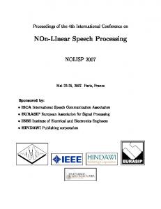
Figure 1: Modelization of acoustic and mechanic echo Fig. 1 schematized the acoustic coupling model. The loudspeaker signal x(t) is coupled to the microphone through the acoustic path h(t) and the resulting echo e(t) is considered to be the result of the convolution of x(t) and h(t): e(t) = x(t) ∗ h(t)
(1)
In this paper we made the assumption to neglect the noise. Accordingly, the microphone signal y(t) is the addition of the useful signal s(t) and of the echo signal e(t). Taking into account the discretized signals x(n) and y(n), we assume also that the discretized echo can be written as e(n) = x(n) ∗ h(n), with h(n) being the discretized echo path of h(t). 3. GAIN LOSS CONTROL IN TIME DOMAIN Gain loss control is one of the oldest attempts to compensate echo and is still commonly used to cope with light echo or in combination with echo cancellation methods [3]. Its principle is to apply an attenuation gain to the microphone (resp. loudspeaker) when the energy of x(t) (resp. y(t)) is bigger than a certain threshold. Only a strongly reduced echo signal is transmitted to the far-end speaker as the loudspeaker and/or the microphone path are attenuated. The disadvantage of the gain loss control however is its behavior in double-talk periods as it can attenuate both path (half-duplex, in other term walkie-talkie effect).
409
Usually for methods working in time-domain, the microphone signal is decreased by an attenuation factor, which is generally a function of the short-term energy of the input signal x(n) and y(n). One possible implementation is to consider the energy difference between the microphone and the loudspeaker signal, Edi f f (n). Accordingly, a hard decision gain loss control computes the attenuation factor to be applied to the loudspeaker path, al (n):
transfer function can be approximatively written as in [2]: H(z) = ³
g f (m) Ã ! ´ M 1 + ∑ ci (m) · z−i 1 − ga (m) · z−T (m)
(5)
i=1
with M being the length of the linear prediction filter (10 in AMR), m the subframe index, ci the LPC coefficients, ga the adaptive gain, T the current pitch delay and g f the fixed gain ( 0 , Edi f f (n) < 0 value. With this formula, the fixed gain can be seen as a 0.5 , Edi f f (n) = 0 , al (n) = (2) multiplicative factor applied to the signal. Accordingly, re1 , Edi f f (n) > 0 ducing g f reduces the signal amplitude. Such a remark can be made for the microphone and the loudspeaker paths. As The attenuation on the microphone path is then computed a result, applying gain loss control in the parameter domain according to: can be principally done by modifying the fixed gains. Then our solution applies a weighting factor on the fixed gain. As schematized in Fig. 2, the attenuation factors are computed am (n) = 1 − al (n) (3) through a control unit. This control unit extracts some parameters from the bitstreams x(k) and y(k) (cf. section 4.2) Such decision rule switches off the microphone path and to compute the energy estimations and to apply regulation lets the loudspeaker path unchanged if the energy of the miPSfrag replacements rules on al and am similarly to the ones previously described crophone is smaller than the energy of the loudspeaker (and in section 3. vice versa). Schematically, it lets signal with high energy unchanged and cuts low energy ones. x(n) x(k) Another possibility is a soft gain-loss control such as: Decoder 0 , 1 E (n) + 0.5 , al (n) = di f f p 1 ,
Edi f f (n) < − 2p − 2p ≤ Edi f f (n) ≤ 2p p 2 < Edi f f (n)
g f ,x (m) ga,x (m)
(4)
Control
To study the transposition of the gain loss control in the parameter domain, we use the Adaptive Multi Rate (AMR) codec [4]. This codec is perfomred on frame of 20 ms divided into 4 subframes of equal length. The codec uses a 10th order linear prediction filter. The Linear Prediction Coefficients (LPC) are computed each frame and are further quantized as Line Spectral Pair (LSP). After filtering of the input signal by the LPC filter, a residual signal is obtained. This signal needs to be transmitted for reconstruction of the speech to the decoder. To do so, first an adaptive codebook search is performed on subframe basis leading to a pitch delay and an adaptive gain value. By subtracting the excitation of the adaptive codebook multiplied with its respective gain a new target signal is obtained. This target signal is used to find the optimal fixed codebook index and fixed gain value. All parameters (LSP, pitch delay, fixed codebook index and both fixed and adaptive gains) are transmitted to the decoder. The first task when transposing the gain loss control methodology in the parameter domain is to find out which codec parameters are relevant. The z-domain synthesis filter
y(k)
h(n) g f ,y (m) ga,y (m)
am (m)
As previously the microphone attenuation is obtained through Eq. (3). Such soft decision avoids principally the step introduced at the border Edi f f (n) = 0 in Eq. (2). The transition is smoothed which gives in the interval Edi f f ∈ [− 2p , − 2p ] complementary gain attenuation on both path. It enhances principally the behavior of the gain loss control during double-talk periods. 4. GAIN LOSS CONTROL IN THE SPEECH CODEC PARAMETER DOMAIN
al (m)
Encoder
e(n) y(n)
s(n)
Figure 2: Gain loss control in codec parameter domain
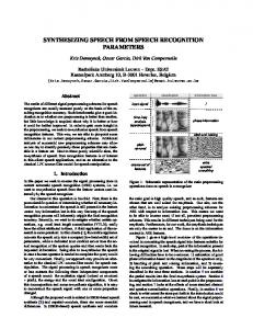
4.1 Energy estimation The speech signal energy estimation is done on sub-frame basis. As these estimations are done in the same way on the incoming bitstream and on the outgoing bitstream, the gain indices l and m are omitted in this section. To compute the ˆ we consider the fixed codebook and we energy estimate E, use the energy of the fixed codeword with constant energy E f multiplied with the corresponding gain g f . Moreover, we include in our computation the adaptive gain ga as a weighting factor of the estimation of the energy made on previous subframe. It leads us to the following formula: ˆ ˆ − 1) ga (m) . E(m) = E f (m) g f (m) + E(m
(6)
The use of the adaptive gain and of the previous estimated subframe energy has a smoothing effect on our estimation. The performance of our estimation is enlightened by Fig. 3. For the signal given in Fig. 3a), the subframe energy is compared to our estimation from Eq. (6). One can see that our estimation is a good approximation of the reference energy. This shows that using the bitstream itself, in other term without decoding, it is possible to get an appropriate estimation of the energy of the signal. This approximation is used in the following to determine our gain loss control rule.
410
speech signal of a female speaker
0.5
0.25
0.25
0
0
−0.25
−0.25
a)
−0.5
0.5
1
1.5 time / s
microphone input speaker A
0.5
2
a)
2.5
−0.5
0
1
2
3
4 time / s
5
6
7
8
7
8
microphone input speaker B (+ echo of speaker A)
0.5
10 0 0.25
−10 energy / dB
−20 −30
0
−40 −50 −0.25
−60
Energy / subframe Energy from parameters
−70
b)
−80 −90 50
100
150
200
250
300 subframes
350
400
450
500
b)
550
Figure 3: Subframe speech signal energy estimation
0
1
2
3
4 time / s
5
6
Figure 4: Gain loss control simulation: microphone input Finally, the gain factor is applied to the fixed gain in the bitstream x(k):
4.2 Specification of the attenuation factors The energy estimation described in Eq. (6) is smoothed to eliminate fast modifications of the estimation between successive subframes. This filtering presents the advantage that small speech pauses are neglected by determining the attenuation factors. The following non-linear filter is thus applied: ½ ˜ − 1) if E(m) ˆ ˜ − 1) ˆ (1 − αr ) E(m) > E(m + αr E(m ˜ E(m) = ˜ − 1) else ˆ + α f E(m (1 − α f ) E(m) (7) with αr < α f . Hence an increase on the speech energy is emphasized (fast reactivity) and reversely the filter reacts slower when the speech energy decreases. Using this strategy short speech pauses, for example pauses in a sentence, are neglected. The filtering is done on the estimated loudspeaker energy Eˆl (m) and on the microphone energy Eˆm (m). These estimations are used to determine the attenuation factors applied on the fixed gains. The factors are in the interval [0 1], so that the fixed gain is either completely attenuated or not at all. In this paper we investigate the use of the soft decision, similar to the one described in Eq. (4) but applied on subframe basis and estimated energy differences: 0 , E˜di f f (m) < − 2p 1 ˜ Edi f f (m) + 0.5 , − 2p ≤ E˜di f f (m) ≤ 2p al (m) = p 1 , 2p < E˜di f f (m) (8) where E˜di f f (m) stands for the logarithmic ratio between the estimationes of the loudspeaker energy E˜l (m) and of the microphone energy E˜m (m): E˜l (m) . E˜di f f (m) = 10 log E˜m (m)
−0.5
(9)
g f ,x (m) = al (m) · g f ,x (m) .
(10)
The weighting factor am (m) is computed similarly to Eq. 3 and is applied to the fixed gain g f ,y (m) of the bitstream y(m). 5. SIMULATION Our simulation was performed using different combinations of speech files. We based the comments of this section on the analysis of one typical example, which includes singletalk mode as well as double-talk periods (Fig. 4 - 6). In Fig. 4 the speech of the far-end speaker (in blue), and the microphone input at the near-end speakers side are shown. The input signal is the sum of the near-end speech (in red) and the echo (in dark red). The VAD of the AMR encoder [4] is used to distinguish between the different speech modes. A colored background in light blue symbolizes single-talk of the far-end speaker, whereas the single-talk mode of the near-end speaker is characterized by a light red background. During double-talk periods the background of the plots are colored purple. The behavior of the control unit is presented in Fig. 5. Subplot a) shows the low-pass filtered energy estimation, Eq. (6) and (7), with αr = 0.7 and α f = 0.95. In single-talk of the far-end speaker (light-blue background) one sees clearly that the estimated energy of the far-end speech is very similar to the estimated energy of the echo. The attenuation and delay of the echo results from the acoustic impulse response h(n). Subplot b) of this figure shows the attenuation factors applied to the gains of the far-end and near-end speaker, respectively. In single-talk mode, the criterion we used for echo attenuation is accurate. The decreasing factors are adjusted
411
estimation of energy
10
loudspeaker ouput at speaker B
0.5
0 0.25
energy / dB
−10 −20
0
−30 −40
−0.25
−50
a)
−60
a) 0
1
2
3
4 time / s
5
6
7
8
attenuation factors
−0.5
0
1
2
0.8
4 time / s
5
6
7
8
6
7
8
loudspeaker output at speaker A
0.5
1
3
0.25
0.6 0 0.4 −0.25
0.2
b)
0
b) 0
1
2
3
4 time / s
5
6
7
8
Figure 5: Gain loss control simulation: control unit
−0.5
0
1
2
3
4 time / s
5
Figure 6: Gain loss control simulation: loudspeaker output 6. CONCLUSION
correctly, i.e. the loudspeaker output is switched off completely when the near-end speaker is talking, conversely the microphone input is interrupted when the far-end speaker is talking. Fig. 5 shows also the limits of the gain loss control during double talk period. Rapid changes of the attenuation factors occur in double-talk. Thus the microphone and the loudspeaker at the near-end speaker side are switched off frequently. The effect of the low-pass filtering on the estimated energy in Eq. (7) can also be seen. Indeed the attenuation factors are not changed before 200 ms after the end of the voice activity detection. Accordingly signals at the end of a word or a sentence would not be decreased which could lead to residual echo situation. Fig. 6 shows the processed speech files. We can see that the speech is not modified during single talk and that the echo is completely canceled. It is also shown that a residual echo, colored dark red, is present during double-talk mode. During double talk, as the attenuation factors can vary from subframe to subframe it impacts the quality of the decoded voice which is varying in energy. Different informal listening tests confirmed the results stated above. During singletalk periods, the echo is completely suppressed. However in double-talk mode the speech files are both modified in such a way that it is not so comfortable to listen to. Our solution is a kind of compromise between full-duplex and half-duplex. During double talk, signals are not switched off but we obtain a certain distortion in the microphone signal. This drawback is nevertheless inherent on gain-loss control, the same bahaviour can be shown for gain-loss control in the time domain. It is then quite natural to obtain the same artefacts through the transposition of the method in the parameter domain.
In this paper it was shown that gain loss control method can be transposed from the time domain to the parameter domain. The simulations confirmed the validity of this transposition and showed really good results in single-talk. This method presents the same compromise between full-duplex and distortion on speech during double-talk period as when applying gain-loss control in the time domain. Further experiments in a real time system and in noisy conditions would give good indications about the robustness of this methodology. We still hope to be able to enhance the double-talk behavior. Using this low complexity mechanism allows to save computational effort. With our method, the energy and the attenuation factors have to be determined only every 40 speech samples. REFERENCES [1] N. Duetsch, H. Taddei, C. Beaugeant, and T. Fingscheidt, “Noise reduction on speech codec parameters,” Review 5th International ITG Conference, January 2004. [2] H. Taddei, C. Beaugeant, and M. de Meuleneire, “Noise reduction on speech codec parameters,” ICASSP, May 2004. [3] E. Haensler, “The hands-free telephone problem: an annotated bibliography update,” in Annales des Telecommunications, 1994, vol. 49, pp. 360–367. [4] 3GPPP TS 26.071, Mandatory Speech Codec Speech Processing Functions; General Description, June 2002.
412