Proceedings of PAC07, Albuquerque, New Mexico, USA
WEPMS022
GAIN SCHEDULED NEURAL NETWORK TUNED PI FEEDBACK CONTROL SYSTEM FOR THE LANSCE ACCELERATOR* Sungil Kwon#, J. Davis, M. Lynch, M. Prokop, S. Ruggles, and P.Torrez LANL, Los Alamos, NM 87545, U.S.A. Abstract The current LANSCE LLRF system is an analog PI Feedback control system which achieves the amplitude and phase error within 1% and 1 degree. The feedback system receives the cavity amplitude and phase and the crosstalk between the amplitude and the phase paths is significant. We propose an In-phase (I) and Quadrature (Q) based feedback control system which easily decouples the crosstalk of I and Q channels. A gain scheduled PI feedback controller with optimally generated set point trajectory reduces the transient peak of the feedback controller and hence reduce the fatigue of the RF amplifier chain. An additional feature of the controller is the Neural network based self-tuning PI feedback, where the neural network tunes the feedback gains to minimize the errors in the least squares sense. The proposed control system is implemented with Altera Stratix II FPGA. The control system is modeled with DSP Builder and automatically generates HDL. Altera SOPC Builder is used for the hardware integration of the DSP Builder model, memories, peripherals, and 32 bit NIOS II embedded processor. NIOS II processor equipped with real time operating system communicates with the host computer via Ethernet, uploads data, computes parameters, and downloads parameters. The proposed control system is tested with the low power test-stand for the robustness of the algorithm.
T
INTRODUCTION
HE primary controllers for the LANSCE feedback system are proportional-integral (PI) controllers. It was built on an analog controller 40 years ago. No network connection, tuning automation were implemented. To obtain the best performance of the linear accelerator (linac) controller systems, 52 individual controller gains should be properly tuned. In addition, the feedback controllers are located in the tunnel, which makes it impossible to tune the system in the central control room. A personnel has to sweep the tunnel to check the controller signals and tune the controller gains manually, observing the oscilloscope display of the signals. Tuning is time consuming and requires automation remotely. In this paper, a self-tuning PI controller scheme supported by the network is proposed. For the tuning, a neural network is implemented in the remote system. Measurement data is uploaded to the remote system via Ethernet, the controller gains are tuned in the remote ___________________________________________
*Work Supported by the United States Department of Energy, National Nuclear Security Agency, under contract DE-AC52-06NA25396 #
[email protected]
07 Accelerator Technology Main Systems
c 1-4244-0917-9/07/$25.00 2007 IEEE
system, and new controller gains are downloaded to the controller via Ethernet. The controller hardware is implemented on the Altera FPGA which is equipped with the NIOS II 32 bit RISC processor. For the controller and receiver/transmitter signal processing hardware design, the VHDL codes are generated using DSP builder. For the integration of the DSP builder system, NISO II processor, Ethernet MAC, and other necessary system components such as external memory, RS232C, SIO, etc., SOPC Builder of Altera is used. NISO II processor receives the tuned controller gains and programs the memory mapped registers. The gain update is performed once at each RF pulse. The tuning of the gains is performed in the remote system which is equipped with Matlab/Simulink.
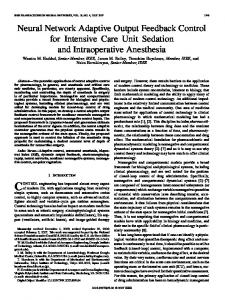
NEURAL NETWORK BASED TUNING Neural networks have attracted the attention of many researchers and have been applied to many fields recently. Since the pioneering work [1], numerous neural networks have been developed and extended their applications from pattern recognition, optimization, to control, dynamic system identification, prediction [2]. Neural networks have very close ties with optimization. Many learning algorithms have been developed based on optimization techniques such as least mean squares and steepest decent algorithms. Neural networks learn from examples rather than having to be programmed in a conventional sense. In this, neural networks resemble the adaptive control/signal processing. The neural network tuning discrete time PI controller configuration is shown in figure 1. The discrete time PI controller is given by u (t ) = u (t − 1) + k p (e(t ) − e(t − 1)) + k i e(t ) (1) e(t ) = r (t ) − y (t ) (2) where t is the sample number. For PI gain tuning, a single neuron is employed [3]. Figure 2 shows a neuron model. In this figure, the total input for the neuron u i is given by ui =
1
∑ wn d n
(3)
n =0
where wn and d n are the individual connection weights and the individual input signals. The output for the neuron y o is y o = f (u i ) (4) The output yo is decided by connection weight w0 , w1 , the squared error function E: T25 Low Level RF
2379
WEPMS022
Proceedings of PAC07, Albuquerque, New Mexico, USA
1 ( y0 − yi ) 2 (5) 2 is defined for weights. A gradient descent method to obtain a minimum value E . For f (u i ) = u i , the weight E=
change Δwn and the update of the weights are given by ∂E ∂y o ∂u i Δwn = −C n = −C n e r d n (6) ∂y o ∂u i ∂wn wn (t + 1) = wn (t ) + Δwn
(7) where C n is a positive constant representing learning step and e r = y o − y i . With the above neural network setting, the PI controller gains K p and K i are corresponding to the neural network weights w0 , w1 , respectively. This is shown in figure 2. The inputs for the neuron are an error between the reference signal and the cavity output signal, the integral of the error. The teaching signal y i is the nominal operating controller output of the gain scheduling.
DSP / SOPC BUILDERS, NIOS II PROCESSOR, AND NETWORK DSP builder is an ALTERA tool that automatically generates HDL codes of the Matlab/Simulink model. It helps the rapid prototyping of the FPGA implementation of the signal processing in mind [4]. It allows the hardware to be abstracted to a higher level so that the FPGA and the system waveform developers can operate in a common environment or be one-in-the-same-person. With this tool, a new design flow consists of five segments: defining architecture, implementing/designing modules, integration of modules, translating the design to physical FPGA, and verifying the part in the lab. SOPC Builder is a system development tool for creating systems based on processors, peripherals, and memories[4]. SOPC Builder automates the task of integrating hardware components into a larger system. The SOPC Builder Link Library in DSP Builder supports peripherals that use the Avalon interface specification and provides custom instruction blocks for use with a NIOS II embedded processor. The Avalon interface specification provides peripheral designers with a basis for describing the address-based read/write interface found on master (for example, DMA controller or a microprocessor) and slave peripherals (for example, a memory, UART, or timer). A system generated by DSP builder functions as a custom peripheral to SOPC Builder. To integrate a DSP Builder design system into a SOPC Builder system, the DSP Builder design system must meet the Avalon interface specification and qualify as a SOPC Builderready component. The Avalon Master and Avalon Slave blocks in DSP Builder provide a seamless flow for creating a DSP Builder block as a custom peripheral and integrating the block into a SOPC Builder system. The Avalon Master and Avalon Slave blocks in DSP Builder 07 Accelerator Technology Main Systems
2380
make it possible to automate the process of specifying Avalon ports that are compatible with the Avalon bus, to support multiple Avalon Master and Slave instantiations, to save time spent hand coding the glue logic that connects Avalon ports to DSP blocks to meet the Avalon Interface Specification, and to generate a component descriptor file (class.ptf) which SOPC Builder can recognize as a component with master or slave ports. With the Avalon blocks in the DSP Builder library, we can design the DSP function and add an Avalon block which makes it a custom peripheral within Simulink environment. Each Avalon block can be instantiated multiple times in a design to implement an SOPC component with multiple master and/or slave ports. NIOS II processor is a general purpose RISC processor core [5]. It provides full 32-bit instruction set, data path, address space, access to a variety of on-chip peripherals, and interfaces to off-chip memories and peripherals. Both the instruction and data buses are implemented as Avalon master ports that adhere to Avalon interface specification. The data master port connects to both memory and peripheral components, while the instruction master port connects only to memory components. The NIOS II architecture provides memory-mapped I/O access. Both data memory and peripherals are mapped into the address space of the data master port. The NIOS II IDE contains the MicroC/OS-II real time operating system (RTOS) with multithread environment and NicheStack TCP/IP Stack software component. These provide designers with the ability to build networked embedded systems applications for the NIOS II processor[5]. The Altera implementation of the NicheStack TCP/IP Stack includes an API wrapper which provides the standard socket API. The SOPC builder system incorporated with NIOS II processor contains an Ethernet interface, or media access controller (MAC) (figure3). The Altera provided NicheStack TCP/IP Stack includes driver support for the SMSC lan911c111 MAC/PHY device and Altera triple speed Ethernet megacore function.
IMPLEMENTATION AND EXPERIMENTAL RESULTS Figure 4 shows the experimental setting. In the Matlab, the Ethernet Client environment is constructed. The FPGA board serves as the Ethernet server which has its own IP address. The system parameters such as the cavity rotation matrix, IF gain, set points I and Q, and time characteristics of the set points I and Q will be set in the customer Matlab graphical user interface (figure 5). The parameters are then transmitted to the embedded processor and then loaded to the registers in the FPGA synchronized with the external RF gate pulse. The necessary data for the RF on period such as the cavity fields I and Q are temporarily stored in the memory and when the uploading is called, the data transmitted to the Matlab Client. T25 Low Level RF
c 1-4244-0917-9/07/$25.00 2007 IEEE
Proceedings of PAC07, Albuquerque, New Mexico, USA
WEPMS022
The data sampling rate for the memory storage is about 1.875 μsec because of the NIOS II CPU. In the Matlab, with the uploaded data, the weights of the neural network are updated. The updated weights then are transmitted to the FPGA and the controller performs the task with the new PI gains. The Ethernet implemented supports the 10 Mbps. Figure 6 shows the cavity I and Q trajectories as the Neural Network updates the weights at each RF pulse.
REFERENCES [1] W. McCulloch and W. Pitts, “A logical calculus of the ideas immanent in nervous activity,” Bulletin of Math. Biophysics, vol 5, pp.115-143, 1943. [2] G. W. Ng, Application of Neural Networks to Adaptive Control of Nonlinear Systems, John Wiley & Sons INC. , New York, 1997. [3] S. Yanagawa and I. Miki, “PID Auto-tuning Controller using a single Neuron for DC Servomotor,” 1992 IEEE International Symposium on Industrial Electronics, pp. 277-280, 1992. [4] Altera, Quartus II Version 7.0 Handbook, 2007. [5] Altera, NIOS II Software Developer’s Handbook, 2007.
Figure 1. Discrete time PI control system
Figure 3. SOPC Builder System including CPU, Ethernet, and DSP Builder System Components
Figure 5. Matlab Graphical User Interface for System Parameter Setting 1800
8th RF Pulse
cavity I
1600 1400 1200 1000 800
Figure 2. Neural Network Tuned PI Control System
600 400 200
cavity Q
0 -200
Figure 4. Experimental Setting 07 Accelerator Technology Main Systems
c 1-4244-0917-9/07/$25.00 2007 IEEE
0
10
20
30
40 50 Sample No
60
70
80
90
Figure 6. Cavity I and Q signals as the neural network proceeds the weight update. Red Dotted lines shows the Shaped Set Point. At the 8th RF pulse, the optimal gain Ki is obtained T25 Low Level RF
2381