JOURNAL OF APPLIED PHYSICS 105, 013103 共2009兲
Carrier localization degree of In0.2Ga0.8N / GaN multiple quantum wells grown on vicinal sapphire substrates Zhen-Yu Li,a兲 Ming-Hua Lo, Ching-Hua Chiu, Po-Chun Lin, Tien-Chang Lu,b兲 Hao-Chung Kuo,c兲 and Shing-Chung Wang Department of Photonics and Institute of Electro-Optical Engineering, National Chiao Tung University, 1001 Ta Hsueh Road, Hsinchu 30010, Taiwan
共Received 12 August 2008; accepted 13 November 2008; published online 6 January 2009兲 In this work, we have grown In0.2Ga0.8N / GaN multiple quantum well 共MQWs兲 epitaxial structure on vicinal sapphire substrates by low pressure metal-organic chemical vapor deposition and investigated the relationship between carrier localization degree and vicinal angles of sapphire substrates. The optical analysis confirmed that the In0.2Ga0.8N / GaN MQWs grown on 0.2°-off sapphire substrate exhibited the smallest carrier localization degree and more ordered In0.2Ga0.8N / GaN MQW structure. In addition, mechanisms for carrier localization in In0.2Ga0.8N / GaN MQWs grown on vicinal substrate were discussed based on the results obtained from the power and temperature dependent photoluminescence measurements. The Raman spectrum showing the in-plane compressive stress of the GaN epitaxial structures grown on vicinal sapphire substrates revealed the relation between the dislocation density and the carrier localization degree in MQWs. From transmission electron microscopy images, the threading dislocation density 共TDD兲 of In0.2Ga0.8N / GaN MQWs grown on 0.2° vicinal sapphire substrate at the bottom of n-GaN layer was about 9.4⫻ 108 cm−2 and reduced to 3.0⫻ 108 cm−2 at the top of n-GaN layer. We also obtained the TDD of 5.6⫻ 107 cm−2 in the MQW region and only 1.0⫻ 107 cm−2 in the p-GaN region. Based on the results mentioned above, 0.2°-off substrate can offer In0.2Ga0.8N / GaN MQW blue light-emitting diode structures with benefits, such as high crystal quality, low defects, and small carrier localization degree. © 2009 American Institute of Physics. 关DOI: 10.1063/1.3055264兴 I. INTRODUCTION
During the last decade of the 20th century, InGaN-based light-emitting diodes 共LEDs兲/laser diodes 共LDs兲 with an emission wavelength from green to blue have been successfully developed and commercialized.1 Even though a large number of threading dislocation densities 共TDDs兲 existed in GaN epilayer growing on sapphire by low pressure metalorganic chemical vapor deposition 共MOCVD兲, the InGaNbased LED/LD device exhibited relatively high luminescent efficiency. Some reports attributed this high luminescent efficiency to the formation of quantum dotlike 共QD-like兲 structures in InGaN multiple quantum wells 共MQWs兲 arising from the low solubility of indium in GaN and nonuniform distribution of indium in InGaN well,2–6 which could enhance the radiative recombination rate of electrons and holes in the wells. Additionally, the optical properties of InGaNbased LEDs were affected by many factors, such as misfit dislocation, stacking faults, antiphase domain, strain, interface roughness, and phase separation,7–10 which arises from the large lattice mismatch and the difference in thermal expansion coefficients between InGaN and GaN. On the other hand, several past reports presented by Shen and co-workers11–14 indicated that 2°-off sapphire substrates could be used to reduce the density of threading dislocations in GaN epilayers by about one order of magnitude, attributed a兲
Electronic mail:
[email protected]. Electronic mail:
[email protected]. c兲 Electronic mail:
[email protected]. b兲
0021-8979/2009/105共1兲/013103/7/$23.00
by the annihilation of threading dislocations at the macrosteps. However, their results were mainly obtained from the epitaxial technique of plasma-assisted molecular beam epitaxy. Additionally, several reports presented the results of MOCVD grown GaN-based epilayers and LED structures on vicinal substrates, their results mainly focused on the analysis of growth characteristics.15–19 In this study, we report the systematic optical and structural characteristics of In0.2Ga0.8N / GaN MQW structures grown on vicinal sapphire substrates with different vicinal angles by low pressure MOCVD system and investigate the effect of offset angles on the carrier localization degrees in MQWs. II. EXPERIMENT
The In0.2Ga0.8N / GaN MQWs were grown on a vicinal sapphire substrate by a commercial LP-MOCVD system with a horizontal reactor. The MO compounds of TMGa, TMIn, TMAl and gaseous NH3 were employed as the reactant source materials for Ga, In, Al, and N, respectively, and H2 and N2 were used as carrier gases. The substrates employed herein were scribed from 2 in. just 共0001兲-oriented sapphire wafers 共0°-off兲 and misoriented ones with their c-axis offset by small angles of 0.2° ⫾ 0.05°, 0.35° ⫾ 0.05°, ¯ 0典 direction. and 1 ° ⫾ 0.05°, respectively, toward the 具112 The epitaxial structures of In0.2Ga0.8N / GaN MQW LEDs comprise a 50-nm-thick GaN buffer layer, a 2-m-thick undoped GaN epilayer, a 2-m-thick n-GaN epilayer, a fivepair In0.02Ga0.98N / GaN prestrained layer, a five-pair
105, 013103-1
© 2009 American Institute of Physics
Downloaded 31 Mar 2010 to 140.113.76.15. Redistribution subject to AIP license or copyright; see http://jap.aip.org/jap/copyright.jsp
013103-2
J. Appl. Phys. 105, 013103 共2009兲
Li et al.
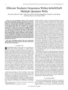
5.0, 1.4, 5.2, and 24.2 meV redshifts for In0.2Ga0.8N / GaN MQWs grown on 0°-, 0.2°-, 0.35°-, and 1°-off sapphire substrates, respectively. Then, the emission peak energy shifts toward higher energy, reaching maxima at a temperature of about 120 K. The blueshifts of emission energy for In0.2Ga0.8N / GaN MQWs grown on 0°-, 0.2°-, 0.35°-, and 1°-off sapphire substrates were 4.9, 1.0, 7.0, and 26.4 meV, respectively. On the other hand, from the fitting of the high temperature region data indicated by the red line in Fig. 1, we found that it can be fitted well by the band-tail-state emission model, and Eq. 共1兲 is as follows:21 Eg共T兲 = Eg共0兲 − FIG. 1. 共Color online兲 PL emission peak energy for In0.2Ga0.8N / GaN MQWs grown on 共a兲 0°-, 共b兲 0.2°-, 共c兲 0.35°-, and 共d兲 1°-offset sapphire substrates plotted as a function of temperature.
In0.2Ga0.8N / GaN active layer, a 0.1-m-thick p-AlGaN window layer, and a 0.1-m-thick p+-GaN contact layer. The thickness of the In0.2Ga0.8N well and GaN barrier in the active layer were around 3.1 and 12.1 nm, respectively, while the thickness of the prestrained layer was about 2.8 nm. In addition, it should be noted that all samples were grown in the same run and therefore the growth conditions were completely the same except the substrate misorientation. The optical properties were investigated by temperature dependent and power dependent photoluminescence 共PL兲 measurements, which were excited with the 325 nm line of a He–Cd laser at excitation power densities of 20 mW. Besides, the carrier lifetime was determined from the temperature dependent time-resolved PL 共TRPL兲. In the TRPL measurement, the signal was excited by a frequency doubled Ti:sapphire laser at a wavelength of 390 nm; the laser output power was 2 mW. The laser pulse width was 200 fs and the repetition rate was 76 MHz. For PL and TRPL measurements, the luminescence was dispersed by a 0.5 m monochromator. Additionally, the luminescence was detected by a water-cooled photomultiplier tube detector for PL measurement and by an air-cooled avalanche photon diode detector for TRPL measurement. The room temperature Raman scattering was used to analyze the stain state of InGaN/GaN MQWs, and the corresponding reciprocal space mapping 共RSM兲 was used to investigate the strain status of MQWs. The distribution and threading behaviors of dislocations in InGaN/GaN MQWs grown on sapphire substrates with different vicinal angles were then studied by cross-sectional transmission electron microscopy 共TEM兲.
Figure 1 shows the temperature dependence of the PL emission peak energy for In0.2Ga0.8N / GaN MQWs grown on sapphire substrates with different vicinal angles. It can be clearly seen that the temperature dependent curves of the PL emission peak energy were relatively anomalous and could not be fitted well by the Varshni empirical formula.20 The emission peak energy shifts toward lower energy when the temperature increases from 14 to 70–90 K, resulting in about
共1兲
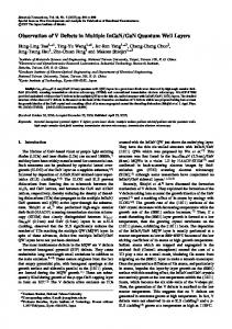
where Eg共0兲 is the bandgap at 0 K, ␣ and  are Varshni’s thermal coefficients, kB is the Boltzmann constant, and is the Gaussian broadening parameter. Thus, the Gaussian broadening parameters of In0.2Ga0.8N / GaN MQWs grown on 关Fig. 1共a兲兴 0°-, 关Fig. 1共b兲兴 0.2°-, 关Fig. 1共c兲兴 0.35°-, and 关Fig. 1共d兲兴 1°-off substrates were determined by Eq. 共1兲 as 9.2, 6.1, 11.5, and 31.6 meV, respectively. We find that the In0.2Ga0.8N / GaN MQWs grown on 0.2°-off sapphire substrate exhibited a relatively less notable S-shaped behavior in comparison with other samples. The temperature dependence of the PL emission peak energy followed an S-shaped path with increasing temperature, indicating the localization phenomena of carrier in In0.2Ga0.8N / GaN MQWs.22 Besides, the report of Yamamoto et al.23 indicated that the carrier localization states were created by the disorder in the atomic arrangement and obtained verification in AlAs/GaAs disordered superlattices 共d-SLs兲. On the other hand, the Gaussian broadening parameter can be seen as an indication of order degree of InGaN/GaN MQWs.24 In other words, the disorder degree of In0.2Ga0.8N / GaN MQWs increased with increasing value of the Gaussian broadening parameter. Hence, we find that the carrier localization degree of the In0.2Ga0.8N / GaN MQWs grown on 0.2° vicinal sapphire substrate is smaller than that of the In0.2Ga0.8N / GaN MQWs grown on the substrates with other offset angles. Figure 2 shows the temperature dependence of integrated PL intensity for In0.2Ga0.8N / GaN MQWs grown on 关Fig. 2共a兲兴 0°-, 关Fig. 2共b兲兴 0.2°-, 关Fig. 2共c兲兴 0.35°-, and 关Fig. 2共d兲兴 1°-off sapphire substrates. Evidently, the temperature dependence of integrated PL intensity cannot be well fitted by the Arrhenius formula. The transients can be well fitted by the relationship of amorphous semiconductors and disordered SLs and given by the following Eq. 共2兲,23,25 I共T兲 =
III. RESULTS AND DISCUSSION
␣T2 2 − , 共T − 兲 kBT
I0 , 关1 + A exp共T/T0兲兴
共2兲
where I0 is the PL intensity at 0 K, T is the temperature, T0 is the characteristic temperature, and A is the tunneling factor. By the fitting the characteristic temperature T0 was estimated to be 112.7, 81.4, 118.3, and 168.7 K for In0.2Ga0.8N / GaN MQWs grown on 0°-, 0.2°-, 0.35°-, and 1°-off sapphire substrates, respectively. Here, the characteristic temperature can be an indication of the energy depth of localized states. Therefore, by comparing the characteristic temperature of all
Downloaded 31 Mar 2010 to 140.113.76.15. Redistribution subject to AIP license or copyright; see http://jap.aip.org/jap/copyright.jsp
013103-3
J. Appl. Phys. 105, 013103 共2009兲
Li et al.
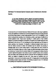
FIG. 3. 共Color online兲 Temperature dependence of rad for In0.2Ga0.8N / GaN MQWs grown on 共a兲 0°-, 共b兲 0.2°-, 共c兲 0.35°-, and 共d兲 1°-off sapphire substrates. FIG. 2. 共Color online兲 Temperature dependence of PL intensity for In0.2Ga0.8N / GaN MQWs grown on 共a兲 0°-, 共b兲 0.2°-, 共c兲 0.35°-, and 共d兲 1°-off sapphire substrates.
samples, we found that the In0.2Ga0.8N / GaN MQWs grown on the 0.2°-off sapphire substrate has the smallest T0 value and that on the 1°-off sapphire substrate has the largest T0 value, suggesting that the carrier in In0.2Ga0.8N / GaN MQWs grown on the 0.2°-off sapphire substrate exhibited the weakest localization effect. These data are in good agreement with the result estimated from the temperature dependence of the PL emission peak energy, as shown in Fig. 1. The carrier decay time of MQWs was expressed as a function of rad and nonrad and given in Eq. 共3兲. In addition, the internal quantum efficiency of luminescence int is given in Eq. 共4兲,26 1 1 1 = + , rad nonrad
int =
nonrad , rad + nonrad
共3兲
共4兲
where rad and nonrad are the radiative and nonradiative lifetimes, respectively. Hence, we can obtain the value of rad by monitoring both and int. The int was obtained by using temperature dependence of the integrated PL intensity.27 Figure 3 shows the temperature dependence of radiative lifetime rad for In0.2Ga0.8N / GaN MQWs grown on 关Fig. 3共a兲兴 0°-, 关Fig. 3共b兲兴 0.2°-, 关Fig. 3共c兲兴 0.35°-, and 关Fig. 3共d兲兴 1°-off sapphire substrates. As we can see, the temperature dependence of rad for all samples exhibited two regions: one can be grouped into the temperature dependent region and the other can be grouped into the temperature independent region. The arrows in Fig. 3 indicate the temperature of transformation between the temperature dependent and independent regions, which are henceforth denoted as turning point. When the temperature is below the turning point, the value of radiative lifetime is temperature independent, indicating that the carrier is not easily delocalized by the thermal energy. When the temperature is above the turning point, the value of radiative lifetime increases with increasing tempera-
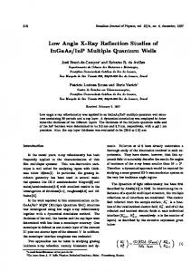
ture, which indicates that the carrier is delocalized by thermal energy with increasing temperature. Therefore, when the In0.2Ga0.8N / GaN MQWs are grown on 0°-off substrate, the turning point is about 140 K. When the vicinal angle is changed from 0° to 0.2°, the turning point is decreased from 140 to 85 K. However, the turning point was about 100 K for the 0.35° vicinal substrate and 140 K for the 1° vicinal substrate. On the other hand, according to the report of Kawakami et al.,26 the excitons exhibited a threedimensional confined feature as the relationship between radiative lifetime 共rad兲 and temperature 共T兲, which is temperature independent. In other words, when the relationship between rad and T is temperature dependent, the excitons exhibit a lower dimensionally confined feature. So the slope for the above turning point in Fig. 3 corresponds to the confinement degree of carriers in InGaN/GaN MQWs, i.e., when the slope is lower, the carriers behave much more like in a three-dimensional confined structure. Hence, from Fig. 3, we can clearly find that the In0.2Ga0.8N / GaN MQWs grown on the 0.2° vicinal substrate has the lowest turning point and has the largest value of P, suggesting that the localization degrees of the carrier and localization depths are lower and shallower than other samples. Figure 4 shows the excitation power dependence of emission energy and the full width at half maximum 共FWHM兲 of In0.2Ga0.8N / GaN MQWs. As we can see, for all samples, when the excitation power increases, the emission peak energy of In0.2Ga0.8N / GaN MQWs shifts toward higher emission energy, resulting in around 69.2, 61.9, 64.3, and 152.6 meV blueshift for In0.2Ga0.8N / GaN MQWs grown on 0°-, 0.2°-, 0.35°-, and 1°-off sapphire substrates, respectively. This behavior of blueshift is very similar to the results obtained in a heavily doped GaAs material system reported by Elsieev et al.28 In addition, Qiu et al.29 indicated that the GaN material with Mg doping exhibited the band-tailing effect. For the InGaN material system, the localized state formed in local potential minima in the band tail. So, the band-filling effect of tails of the density of states can be considered for the possible mechanism of this blueshifted behavior. Additionally, if the depth of the localized state be-
Downloaded 31 Mar 2010 to 140.113.76.15. Redistribution subject to AIP license or copyright; see http://jap.aip.org/jap/copyright.jsp
013103-4
J. Appl. Phys. 105, 013103 共2009兲
Li et al.
FIG. 4. 共Color online兲 Emission energy and FWHM of In0.2Ga0.8N / GaN MQWs grown on 共a兲 0°-, 共b兲 0.2°-, 共c兲 0.35°-, and 共d兲 1°-off sapphire substrates plotted as a function of excitation power.
comes deeper, the energy level, which could be occupied by carriers, also becomes higher, resulting in a larger blueshift as the excitation power is increased. Hence, in our experiment, the blueshift for In0.2Ga0.8N / GaN MQWs grown on the 0.2°-off sapphire substrate is only 61.9 meV, which is lower than others, indicating that the localized states in the band tail are easily filled as excitation power density is increased. Therefore, for the 0.2°-off case, the weaker carrier localization degree and shallower energy depth of localized states could be responsible for rapid state filling. On the other hand, for all samples, the FWHM of the PL spectrum can be separated into two regions, which are henceforth denoted as regions I and II. These two regions are divided by dashed red lines, as shown in Fig. 4. For region I, the FWHM of the PL spectrum decreases with increasing excitation power. It is well know that the InGaN/GaN MQWs existed large biaxial stress due to large lattice mismatch and thermal expansion coefficient incompatibility between GaN and InGaN, resulting in a large piezoelectric field along the c-plane orientation, thus forming the quantum confined Stark effect 共QCSE兲. Since the excitation power increased, resulting in the increase in density of carrier in localized states, the QCSE became weak arising from the excess-carrier-induced screening effect. Thus, the FWHM of the PL spectrum decreased first. However, for region II in Fig. 4, the FWHM of the PL spectrum increases to values around 62.6, 60.3, 63.7, and 168.5 meV for 0°-, 0.2°-, 0.35°-, and 1°-off samples, respectively. Again, the 0.2°-off sample showed the smallest broadening degree. Generally speaking, a larger phase separation degree will increase the density of QD-like structures, resulting in a large spectral broadening of the emission bands since there is narrower interdot spacing,
indicating that the In0.2Ga0.8N / GaN MQW structure became more disordered. In other words, the 0.2°-off sample showed a weaker localization effect than the others. Figure 5 shows the Raman spectrum for InGaN/GaN MQWs grown on vicinal substrates. The Raman spectra show two Raman shift peaks: one can be attributed to the E2 共high兲 mode of the GaN epilayer and another can be attributed to the A1 共LO兲 mode of GaN epilayer. The Raman shift peak of E2 共high兲 for MQWs grown on 0°-, 0.2°-, 0.35°-, and 1°-off sapphire substrates was located at around 569.7, 570.4, 569.7, and 569.7 cm−1, respectively. We can calculate the strain value of MQWs by the following equation:30 ⌬ = E2 − 0 = C ,
共5兲
where ⌬ is the Raman shift peak difference between the strained GaN epilayer and the strain-free GaN epilayer. C is the biaxial strain coefficient, which is 4.1 cm−1 / GPa.31 The calculated in-plane compressive stresses were about 6.5, 7.7, 6.7, and 5.7 GPa for InGaN/GaN MQWs grown on 0°-, 0.2°-, 0.35°-, and 1°-off sapphire substrates, respectively. Compared with the 0.2°-off sample, the strain relaxation degree of others are about 16%, 13%, and 26% for 0°-, 0.35°-, and 1°-off samples, respectively. In general, the relaxation could be due to creation of dislocation. So, the larger strain is probably connected to less dislocation density. In addition, our RSM data indicated that In0.2Ga0.8N / GaN MQWs grown on the 0.2° vicinal sapphire substrate have the smallest degree of lattice relaxation, i.e., has the largest strain.32 For the heteroepitaxial structure, the density of defects, such as threading dislocations, V defects, and so on will increase with increasing degree of lattice relaxation in the epilayer. In
Downloaded 31 Mar 2010 to 140.113.76.15. Redistribution subject to AIP license or copyright; see http://jap.aip.org/jap/copyright.jsp
013103-5
Li et al.
J. Appl. Phys. 105, 013103 共2009兲
FIG. 5. Room temperature Raman spectrum for In0.2Ga0.8N / GaN MQWs grown on 共a兲 0°-, 共b兲 0.2°-, 共c兲 0.35°-, and 共d兲 1°-off sapphire substrates.
other words, the epitaxial structure of In0.2Ga0.8N / GaN MQWs grown on the 0.2° vicinal sapphire substrate seems to exhibit the lowest defect density compared with other samples. Hence, the results from the RSM analyses are in good agreement with those presented by the studies of Raman described above. Additionally, we used TEM to investigate crystalline quality of In0.2Ga0.8N / GaN MQW blue LEDs grown on a vicinal sapphire substrate with different vicinal angles. Figures 6共a兲–6共c兲 show the cross-sectional bright field TEM images of the interface between n-GaN and sapphire, which was the bottom part of the n-GaN epilayer. As can be seen from Fig. 6共a兲, when the n-GaN epilayer is grown on the 0°-off sapphire substrate, we can clearly find that the n-GaN epilayer existed many horizontal and vertical types of dislocation, and the TDD at the bottom of the n-GaN layer was estimated to be as high as 1.6⫻ 109 cm−2. In addition, there were some dislocations threading through the top of the n-GaN to the MQWs even into the top surface of the p-GaN epilayer, as shown in Fig. 7共a兲. From the image in Fig. 7共a兲, the TDDs at the top of n-GaN, MQWs, and p-GaN were estimated to be 6.3⫻ 108, 1.5⫻ 108, and 2.2⫻ 108, respectively. On the other hand, when vicinal angle was changed from 0° to 0.2°, it can be clearly found that the crystallography of the n-GaN epilayer was drastically different from that of the n-GaN epilayer on the 0° vicinal sapphire substrate. Much fewer dislocations were observed throughout the observed area. As shown in Fig. 6共b兲, the TDD at the bottom of the n-GaN layer was about 9.4⫻ 108 cm−2. Only one dislocation can be observed in the top of the n-GaN epilayer, while a clear interface between the well and barrier in MQWs can be observed without any interruption of threading dislocation throughout the observed area. So the dislocation densities of the top of n-GaN, MQWs, and p-GaN were
considered to be less than 3.0⫻ 108, 5.6⫻ 107, and 1.0 ⫻ 107 cm−2, respectively, as shown in Fig. 7共b兲. Finally, when the vicinal angle was up to 1°, bunches of threading dislocations can be seen radiating vertically from the interface between n-GaN and sapphire into the MQW region p-GaN layer, as shown in Figs. 6共c兲 and 7共c兲. Therefore, quite a large number of dislocations were presented in the whole film on the 1°-off substrate, as shown in Fig. 6共c兲. The
FIG. 6. 共Color online兲 Bright field TEM cross-sectional images, which was focused on the interface between n-GaN and sapphire substrate for In0.2Ga0.8N / GaN MQWs grown on 共a兲 0°-off, 共b兲 0.2°-off, and 共c兲 1°-off sapphire substrate. The diffraction condition is g0002.
Downloaded 31 Mar 2010 to 140.113.76.15. Redistribution subject to AIP license or copyright; see http://jap.aip.org/jap/copyright.jsp
013103-6
Li et al.
FIG. 7. 共Color online兲 Cross-sectional TEM images of InGaN/GaN MQWs grown on 共a兲 0°, 共b兲 0.2°, and 共c兲 1° vicinal sapphire substrates.
TDD evaluated at the bottom of the n-GaN region was as high as 2.3⫻ 109 cm−2. From Fig. 7共c兲, we can obtain the TDD of 1.2⫻ 109, 6.2⫻ 108, and 6.2⫻ 108 cm−2 for the top of n-GaN, MQWs, and p-GaN, respectively. In addition, it should be noted that, for this degree of TDD, a relatively rough top surface can be found, as shown in Fig. 7共c兲. On the other hand, to better understand the effect of dislocation on the formation of microstructures or QD struc-
J. Appl. Phys. 105, 013103 共2009兲
tures of In0.2Ga0.8N / GaN MQWs, the high resolution TEM images of In0.2Ga0.8N / GaN MQW region was performed, as shown in Fig. 8. As can be seen, the difference in In0.2Ga0.8N / GaN MQWs between the three samples was relatively large. Besides, the microstructures or QD structures can be clearly observed for In0.2Ga0.8N / GaN MQWs grown on 0° and 1° vicinal substrates, and the spacing between these microstructures or QD structures was estimated to be 1–1.3 nm for the 0°-off sample, as shown in Fig. 8共a兲, and nearly linking together for the 1°-off sample, as shown in Fig. 8共c兲. However, when In0.2Ga0.8N / GaN MQWs were grown on the 0.2° vicinal substrate, the In0.2Ga0.8N / GaN MQWs exhibited relatively perfect crystalline structure and without any microstructures or QD structures to be observed, as shown in Fig. 8共b兲. The nonuniform distribution of indium and the phase separation in the InGaN well were not the main reason for resulting in the difference of In0.2Ga0.8N / GaN MQWs between the three samples since they were grown in the same run. The misorientation of the substrate could be responsible for such a great difference in In0.2Ga0.8N / GaN MQWs between the three samples since the appropriately misoriented sapphire substrates can reduce the TDD in MQWs. Besides, the microstructures or QD structures can result in rougher interfaces in In0.2Ga0.8N / GaN MQWs. Therefore, by comparing the results in Fig. 8 with those in Figs. 6 and 7, we can demonstrate that the In0.2Ga0.8N / GaN MQWs grown on the 0.2° vicinal substrate exhibited more order structures due to the reduction in threading dislocation, radiating from the interface between GaN and sapphire. From the analyses described above, our measurement results suggested that In0.2Ga0.8N / GaN grown on the 0.2°-off
FIG. 8. 共Color online兲 High resolution TEM images of InGaN/GaN MQW region for 共a兲 0°-, 共b兲 0.2°-, and 共c兲 1°-off sample.
Downloaded 31 Mar 2010 to 140.113.76.15. Redistribution subject to AIP license or copyright; see http://jap.aip.org/jap/copyright.jsp
013103-7
J. Appl. Phys. 105, 013103 共2009兲
Li et al.
sapphire substrate consistently showed the smallest carrier localization degree. The past report indicated that localized states in the tail resulted from fluctuations of In content, inhomogeneous lattice deformations, and dislocation density in the InGaN/GaN material system.33 In other words, our TEM data confirmed that the localization degree of carriers in InGaN/GaN MQWs could increase with increasing misfit dislocation density and the degree of phase separation of InGaN. For our present case, the improved crystal quality of In0.2Ga0.8N / GaN MQWs can be attributed to the use of the 0.2°-off sapphire substrate, whereby the localization degree of carriers in In0.2Ga0.8N / GaN MQWs grown on the 0.2°-off sapphire substrate was the least significant. However, further studies of crystal quality grown on vicinal sapphire substrates are therefore necessary and are in progress. IV. CONCLUSION
In summary, we systematically report the optical characteristics of In0.2Ga0.8N / GaN MQW structure grown on vicinal sapphire substrates with different offset angles by low pressure MOCVD. Our study finds that the carrier localization degrees of the In0.2Ga0.8N / GaN MQW structure are very sensitive to the offset angles of the vicinal substrates. In comparisons with the four different samples, temperature dependent PL emission peak energy analysis shows the anomalous behavior, where the Gaussian broadening parameter of MQWs grown on the 0.2°-off substrate was estimated to have a small value of 6.1 meV. Similarly, MQWs grown on the 0.2°-off substrate exhibit the smallest characteristic temperature of 81.4 K obtained by temperature dependent PL intensity. In addition, the low confinement dimension of carriers in MQWs grown on the 0.2°-off substrate obtained by temperature dependence of rad further indicates a weak localization effect. Finally, room temperature Raman spectrum demonstrated that the largest stress of MQWs grown on the 0.2°-off sapphire substrate was estimated to be 7.7 GPa could explain the higher crystal quality grown on the suitable vicinal substrate, resulting a lower dislocation density and fewer localization centers. Besides, the TEM images revealed that the 0.2°-off sapphire substrate could be used to reduce the dislocation density, whereby the TDD at the bottom of the n-GaN layer was about 9.4⫻ 108 cm−2; the TDD at the top of the n-GaN layer reduces to 3.0⫻ 108 cm−2, 5.6⫻ 107 in MQW region, and only 1.0⫻ 107 cm−2 in the p-GaN region. Therefore, an In0.2Ga0.8N / GaN MQW blue LED structure with high quality, low defects, and small carrier localization degree can be achieved on the 0.2°-off substrate. ACKNOWLEDGMENTS
The authors are grateful to the National Science Council of the Republic of China, Taiwan, for financially supporting
this research under Contract No. NSC 96-2221-E009-067. S. Nakamura, T. Mukai, and M. Senoh, Appl. Phys. Lett. 64, 1687 共1994兲. G. B. Stringfellow, J. Cryst. Growth 27, 21 共1974兲. 3 G. B. Stringfellow, J. Cryst. Growth 58, 194 共1982兲. 4 I-h. Ho and G. B. Stringfellow, Appl. Phys. Lett. 69, 2701 共1996兲. 5 S. Chichibu, T. Azuhata, T. Sota, and S. Nakamura, Appl. Phys. Lett. 69, 4188 共1996兲. 6 K. P. O’Donnell, R. W. Martin, and P. G. Middleton, Phys. Rev. Lett. 82, 237 共1999兲. 7 N. Nanhui, W. Huaibing, L. Jianping, L. Naixin, X. Yanhui, H. Jun, D. Jun, and S. Guangdi, J. Cryst. Growth 286, 209 共2006兲. 8 H. K. Cho, J. Y. Lee, G. M. Yang, and C. S. Kim, Appl. Phys. Lett. 79, 215 共2001兲. 9 J. C. Zhang, D. S. Jiang, Q. Sun, J. F. Wang, Y. T. Wang, J. P. Liu, J. Chen, R. Q. Jin, J. J. Zhu, H. Yang, T. Dai, and Q. J. Jia, Appl. Phys. Lett. 87, 071908 共2005兲. 10 Y.-H. Cho S. K. Lee, H. S. Kwack, J. Y. Kim, K. S. Lim, H. M. Kim, T. W. Kang, S. N. Lee, M. S. Seon, O. H. Nam, and Y. J. Park, Appl. Phys. Lett. 83, 2578 共2003兲. 11 X. Q. Shen, K. Furuta, N. Nakamura, H. Matsuhata, M. Shimizu, and H. Okumura, J. Cryst. Growth 301–302, 404 共2007兲. 12 X.-Q. Shen, M. Shimizu, and H. Okumura, Jpn. J. Appl. Phys., Part 2 42, L1293 共2003兲. 13 X. Q. Shen, H. Okumura, K. Furuta, and N. Nakamura, Appl. Phys. Lett. 89, 171906 共2006兲. 14 X. Q. Shen, H. Matsuhata, and H. Okumura, Appl. Phys. Lett. 86, 021912 共2005兲. 15 S. Keller, N. A. Fichtenbaum, F. Wu, D. Brown, A. Rosales, and S. P. DenBaars, J. Appl. Phys. 102, 083546 共2007兲. 16 J. C. Lin, Y. K. Su, S. J. Chang, W. H. Lan, K. C. Huang, W. R. Chen, Y. C. Cheng, and W. J. Lin, IET Optoelectron. 1, 23 共2007兲. 17 D. Lu, D. I. Florescu, D. S. Lee, V. Merai, A. Parekh, J. C. Ramer, S. P. Guo, and E. Armour, Phys. Status Solidi A 200, 71 共2003兲. 18 S.-W. Kim, H. Aida, and T. Suzuki, Phys. Status Solidi C 1, 2483 共2004兲. 19 K. Tachibana, H. Nago, and S. Nunoue, Phys. Status Solidi C 5, 2158 共2008兲. 20 K. P. O’Donnell and X. Chen, Appl. Phys. Lett. 58, 2924 共1991兲. 21 P. G. Eliseev, J. Appl. Phys. 93, 5404 共2003兲. 22 R. Intartaglia, B. Maleyre, S. Ruffenach, O. Briot, T. Taliercio, and B. Gil, Appl. Phys. Lett. 86, 142104 共2005兲. 23 T. Yamamoto, M. Kasu, S. Noda, and A. Sasaki, J. Appl. Phys. 68, 5318 共1990兲. 24 A. Bell, S. Srinivasan, C. Plumlee, H. Omiya, F. A. Ponce, J. Christen, S. Tanaka, A. Fujioka, and Y. Nakagawa, J. Appl. Phys. 95, 4670 共2004兲. 25 R. A. Street, T. M. Searle, and I. G. Augustein, in Amorphous and Liquid Semiconductors, edited by J. Stuke and W. Brenig 共Taylor & Francis, London, 1974兲, p. 953. 26 Y. Kawakami, Y. Narukawa, K. Omae, Sg. Fujita, and S. Nakamura, Phys. Status Solidi A 178, 331 共2000兲. 27 R. C. Miller, D. A. Kleinman, W. A. Nordland, Jr., and A. C. Gossard, Phys. Rev. B 22, 863 共1980兲. 28 P. G. Eliseev, M. A. Man’ko, A. I. Krasil’nikov, and I. Z. Pinsker, Phys. Status Solidi 23, 587 共1967兲. 29 C. H. Qiu, C. Hoggatt, W. Melton, M. W. Leksono, and J. I. Pankove, Appl. Phys. Lett. 66, 2712 共1995兲. 30 R. Seitz, T. Monteiro, E. Pereira, and M. Di Forte-Poisson, Phys. Status Solidi A 176, 661 共1999兲. 31 J. Ager, T. Suski, S. Ruvinov, J. Krueger, G. Conti, E. Weber, M. Bremser, R. Davis, and C. Kuo, Mater. Res. Soc. Symp. Proc. 449, 775 共1997兲. 32 Z.-Y. Li, W.-Y. Uen, M.-H. Lo, C.-H. Chiu, P.-C. Lin, C.-T. Hung, T.-C. Lu, H.-C. Kuo, S.-C. Wang, and Y.-C. Huang 共unpublished兲. 33 J. H. Chen, Z. C. Feng, J. C. Wang, H. L. Tasi, J. R. Yang, A. Parekh, E. Armour, and P. Faniano, J. Cryst. Growth 287, 354 共2006兲. 1 2
Downloaded 31 Mar 2010 to 140.113.76.15. Redistribution subject to AIP license or copyright; see http://jap.aip.org/jap/copyright.jsp