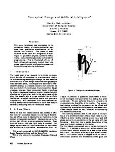
Figure 7 - Schematic of GGSF Breadboard Particle Generator. .............⢠..... This is an extremely ambitious schedule consistent with the new NASA theme of faster ...
NASA-CJ to Space ShuUle requirements
Particle. collected "n Clef, C£3 :n'-'
~ I>'
.
.
~ \.
~ ~ ~ L> ~ :,.
~
~
~
'!:, ";. ~ ""'./"/"'/'//'/'/"/'/'/"~ ....
"
....
"
Lines of Constant Total Particle Mass in Grams AssumIng a Material Density of 2.5 grams{cc And a Chamber Volume of 67,000 cc (Le. Geologic Dust in the Large GGSF Chamber)
1E+10 1E+9 0 0
~ 1E+8 .: Q)
"\ "
t1l
1E+7
\..... 5 . . . . \"
., ...................... . .
J::
U
oS
"
"
.0
E
\..',
.. ...~ ........ . ""'" ................. .............. '.
1E+6
~ Ow
c: Q)
1E+S
0
.... Q)
.0
E
1E+4
:J
Z
Q)
13
:et1l 0...
1E+3 1E+2 1E+1 1E+O 1E-4
1E-3
1E-2
1E-1
1E+O
1E+1
1E+2
1E+3
1E+4
Particle Diameter, microns
Figure 4 - GGSF Requirements for Solid Particle Clouds.
To determine performance of the particle generator, several diagnostic .techniques were utilized. The primary method involved collection of the dispensed particles on a filter, and subsequent microscopic determination of the percentage of mono-particles. A laser beam passing in front of the particle generator output was monitored for extinction as another diagnostic, since dilution of the particles was found to be related to the percentage of mono-particles. A third diagnostic was employed for a limited time in order to qualitatively monitor the cloud motion in the test cell after dispensing. This was a sheet of laser light optically viewed. The GGSF breadboard can be used to test concepts for sample generation, collection, and manipulation. Cleaning techniques for the chamber windows and walls can also be tested, as the small particles can be sprayed on these surfaces with the deagglomerator. These future studies will help answer science and technology questions and reduce risks associated with the GGSF concepts.
23
A detailed report on the breadboard development is included in Appendix A. Which details the development requirements, history, hardware, and characterization tests. This section provides an overview of the results of the breadboard development task. The goals and objectives of the breadboard are discussed in section 5.1. The hardware development is discussed in section 5.2, which includes the trades, parameters, and hardware descriptions. Sections 5.3 and 5.4 respectively present the approach to the test plan, and the results of the tests. As the demonstration of the particle generator breadboard was limited during this activity, section 5.5 recommends the further work that would extend our understanding of the breadboard operation and repeatability. To predict the perfonnartce of a particle generator with the wide variety of particle types, sizes, and quantities that could be required during the GGSF mission, extensive characteri7.ation is required. Section 5.6 discusses how to fully define the perfonnance of this device for the GGSF applications.
5.1 Development Objectives
The goal in developing and building a GGSF laboratory breadboard system was to demonstrate GGSF particle generation techniques and concepts, and 'perfonn particle collection and analysis measurements. The primary objectives in developing the GGSF laboratory particle generator breadboard included: o
identification of candidate techniques for storing, deagglomerating, and dispensing dry solid particles that cover a broad range of the GGSF strawman experiment science and technical requirements;
o
develop and test laboratory breadboard components that demonstrate the feasibility of the selected particle generation technique to meet a representative subset of the science and technical requirements, including parameters of particle size, type, degree of deagglomeration, total mass, etc.;
o
demonstrate the potential for gravity-independent operation of the selected technique;
o
qualitatively characterize the flow field (velocity as a function of time in three dimensions) of the dust cloud generated in the test chamber;
o
identify configurations and technical issues uncovered during the development and testing of the laboratory breadboard system;
o
identify further future development program efforts necessary to fully characterize the . selected particle generation device;
o
maintain a flexible breadboard configuration allowing for utilization in facilities other than a ground-based laboratory.
24
5.2 Key Breadboard Trades, Parameters, and Hardware Configurations The breadboard was designed to fulfill the objectives by allocating requirements to the three subsystems. A particle generator subsystem provides the sample to be generated. The chamber subsystem provides a pseudo-quiescent volume for the sample to be contained within and measurements to be taken. The breadboard was limited to room temperature and pressure, and no attempt was made to control either pressure or temperature during this study although as Table 7 indicates, the experiment requirements span broad ranges of pressure and temperature. The diagnostics subsystem provides the ability to quantify the particle properties. The laboratory breadboard subsystems and requirements are described in Table 8. The breadboard is flexible in design and application, allowing for the design of many types of experiments, and utilization in facilities other than the ground-based laboratory. Table 8 - Summary of Breadboard Subsystems. ""
I
I
Subsystem Particle Generator
0 0 0 0
Chamber
0 0 0
Diagnoatic.
0 0 0 0 0
• DOt included
I
Breadboard Requirementa
Breadboard DelCription
Dispense dry spherical particle., and dUll particle., in the 1-10 IUJl aizc range, u a cloud ofain:le particle. Provide adequate containment of particle. prior to diJpenam, Minimize carrier gu for operation Adaptable to spaco-bued operation (.ize, weight, robustne.., gravity-independent)
•
Approximate volume of OOSF teat chamber Allow viJual acce.. for monitorm, particle action Provide porta for particle introduction & collection
Plexigla.. cylinder - 60 x 60 cm
Monitor particle denaity at ooz:zIe Collect particle. and perform microlCopic ana1yw of deagglomeratioll effectivene.. Photograph particle. through microlCope for qualitative data verification Obtain repreaeDlative SEM photo. of data Record operationa for performance ana1y.i.
• • • • • •
•
Conical aerodynamic blaat-dugglomerator for leparatinz and disperam, particle. in a cloud Cartridge-like storage with pre-roixinz gu jeta
Video ~170)· Luer light abeet illumination· Angular lCatterm, of laaer light Extinction Silicon photodiode Off-line· - Polaroid Camera - miCrolCope -SEM
in delivered breadboard hardware
The breadboard is schematically represented in Figure 5. A photograph of the laboratory breadboard with the particle generator, test chamber, laser and detector diagnostics, and valve controller is shown in Figure 6. A complete parts list can be found in section 7 of Appendix A.
5.2.1 Particle Generator - The majority of the breadboard effort was devoted to development and characterization of the particle generator. A representative particle generation 25
I
Va Ive Contr-o I E I actron i cs
Sample Oi lution Control Valve Sample Injection Control Valve
Pressure Regulators
Oeagg IOlflen:3.tor
Light Sheet Test Chamber
Extinction
Laser Setup
Laser
Samp I e Co I I ect i on Fi Iter
- Schematic:
R«~presentation
of the Laboratory Breadboard.
technique was selected and developed to address several. GGSF science requirements. This generator delivers solid particles into the test chamber as a cloud of singlets. Its operation must be for a low-gravity envifiOnment!, but it must also work in a one-g-laboratory. A review of the commercial and laboraltory systems, revealed that most m~thods rely on gravity, do not assure complete agglomeration, or uSle extensive amounts of carrier gas. Some methods only work for large particles (e.g., millimeter size). Section 4.2 of NASA CR177606, 1he GGSF Final Report, discussed some of the techniques, which include fluidi7.ed bed, ~LSpiration feeder, and ;auger feeder methods. The selected technology was an aerodynamic deaggloffiierator, like lthat used in a micromerograph (described in section 1.7 of Appendix A). This m~:thod appeared to have the highest potential for meeting GGSF requirements for a broad range of sizes and quantities, as well as adaptability'to low-gravity operation. This deagglomerator functions by shearing particl(~s apart in a gas stream that passes through an 26
expanding passage. Several modification:~ were made to the technology to: •
improve the deagglomerntiCln performance - though no information could be found that quantified perfolmance of the micromerogrnph deagglomerntor, our initial tests indilcated that performance was limited to about 65% deagglomerntion. The modiftcations allowed flexibility to vary the parnmeters that affect the deagglomeration performance, including samplc~ feed rate, sample figure 6 .. Photograph of the GGSF laboratory breadboard. dilution in the (:aIrier gas, and carrier gas pressure.
•
improve sample: storagl~ - increasing the quantity of sample material that can be dispersed is to mee~t the GGSF science and technical requirements. The micromerograph dispenses approximately 0.05 cm3 , which was increase to .20 cm3 in the GGSF breadboard. Additionally, d~~upIing of the storage technique from gravity was required. requir(~
•
minimize the carrier gas consumption - the GGSF chamber environment is controlled, and introduction of lcanier gas must be minimized to avoid contamination of the environment.
The characteristics of the particle generator are described in Table 9. A graphical representation of the particle generator b shown in Figure 7, and a photograph of it is shown in Figure 8. The blast deagglomerator performance is affected by three distinct, but not independent, operational parnmeters: storage of particles prior to disp€msing, dilution of particles with carrier gas prior to introduction into· the deagglomerator, and deagglomeration, or separating of particles into singlets. 5.2.1.1 Sample Storage: Stornge of the sample in the particle generator prior to dispersion is an issue. The selected method must: •
be adaptable to lthe range of particle quantities and sizes required; 27
Table 9 - Particle Generator Characteristics.
I
Critera Type of particles dispensed
I ChU3cteciati~
I
Designed for dry solid., 1-100 pm diameter, may work for broader range of particle lize. Tested using: o Gla.. micro-sphere., 10.2 pm diameter o Gla.. micro-sphere., 2.1 pm diameter • Arizona tell dUll, graded, 5-10 pm diameter
Volume of ItOrcd particl:.
0.08 cc tested with complete ruccess; up 10 6.4 cc tested with promising results after more development.
Method of particle ejection
SlOred particles pushed out with gaa Itrcam, diluted with more ga8, and palled through aerodynamic dcagglomeralOr inlO test chamber. G8I requirement ia dependent on percent of deagg\omeration and particle type, as indicateJ in Appendix A.
i"
o
keep samples dry and isolated;
o
predictably contain and release samples in a lowgravity environment.
The sample storage of the standard deagglomerator is for small quantities of material, on the order of 0.05 cm3, and depends on gravity to keep the sample in a position for delivery to the deagglomerator. The particles are entrained in a gas flowing over a bed of particles, which also serves as the dilution method.
1Ua;T10Ii
f
DI$PO-No_-
..... ----;..----------:,;----- :-- .--'-"-'-"-'-1-'-'-' -.-..-.- ..--
# •• - •••••••
_. -
••• - - - - . - - - - ; •• - - - . - • • • • • _
•••••• _
•••• - . . . . . . . . . . . . __ .M . . . . . . - - •••••••
, ; T.----."..
_M . . . . .
I •••• _
• • • M. _ •••••• _ _ _ _ _ _ _ . , • _ _ _ _ _ _ _ " • • M
_••
~.-.-_..
• _ _ ...... _ _ _ _ _ _ _ ••• _
•••••• _
••••••• __ ••
j 10,-,-'·
o
ro
- ..
f-~~'o
~
. . .- 3Q
~
~
100
120
Pressure (psig) rricron .....- 7Q rricron ~ 1'8 mcron
Figure 10 - Graph of Deagglomeration vs. Pressure for 3 slit widths.
A repeat of a few sample test points using the 10 I'm glass spheres indicated good correlation with the data acquired using the Arizona dust. Tests perfonned using 2 I'm glass spheres at several test points indicated a reduction of deagglomeration percentage to 86-91 %, however, no attempt was made to optimize particle generator settings for this sample material due to the limited resources available. The degree of deagglomeration was measured by microscopic inspection of particles that settle onto fine filters placed in the quiescent environment of the test chamber. Examples of selected Scanning 36
Electron Microscope: photographs are shown in Figure 11 amd Figurre 12. More photographs cam be found in sections 3.3 through 3.:5 of Appendix A.
5.4.2 Dispersion Flow Peiformance * The dispersion flow was evaluatc~ qualitatively by observing the cloud IOf dispe~rsed sample in the test chamber by shining :a sheet of light through the cloud. It was observed that the particle cloud impacted the test chamber wall opposite the particle generator quite rapidly (on the order of a few seconds or less). This is an undesi.rable interaction, as particles may be deposited on the walt. Some further investigation showed that a jet of gas, equal in momentum and opposite in direction:. may alleviate this rapid interaction, while enhancing the mixing of the cloud in the chamber. More details of this testing (!an be found in AppendiK A, but only a limite.d amount IOf data has been collected to datle.
Figure 11 - SEM photograph of 6-10
pm Arizona Test Dust.
5.4..~ Dependance on Gravity - The sample holder that was designed for the breadboard was based on the need to opera1te independently of gravity. Several qualitative tests werc~ performed to verify this capability. Due to the cartridge type design, the first verification of gravi~y indep~~ndence was to operate the sample holder in a horizontal position, and determine if all the sample is expellled during operation. Unexpened sample would indicate a potential problem. Sample holders of various diameters were tested for this phenomena, from 0.:50 inch to 0.05 inch diameter. Above .125 inch diameter, particles were being left in the sample holder; therefore the .125 inch, or 3 mm id tube was USIOO. The tests w€~re continued at a vertical orientation and the results indicate that the sample holder design is adequate for low gravity operations. Figure 12 - SEM photograph of 2.1 pm glass spheres.
37
5.5 Future Recommended Demonstration Tests of the Existing Breadboard
A carefully focused but limited set of data was obtained during this effort. A more complete data set should be obtained to better quantify the performance of the blast deagglomerator under the operating conditions required for the GGSF S&T requirements. These data should be acquired on the breadboard device so deficiencies can be identified prior to the flight hardware design, and flexibility in the science requirements, if any, can be accommodated. o
The mass of particles during this test series was limited to 85 mg. The sample holder can contain up to 200 mg. The test matrix should be expanded to increase the sample quantities as well as other sample material types.
o
The accomplished test matrix focused on 10 I'm particles, with limited data and no . optimization for 2 I'm particles, and no data for smaller than 2 I'm or larger than 10 I'm particles. The breadboard particle generator should be tested with other particle sizes to verify the ability to optimize for, and deagglom~rate various particle sizes outside of 10 I'm.
o
The deagglomeration percentage is very dependent on the dilution of the particles in the carrier gas. The carrier gas can affect the chamber environment detrimentally for some GGSF experiments. A thorough characterization matrix will result in a gas requirement vs. deagglomeration percentage that can be used to better define the GGSF experiments or changes to science requirements that can allow this type of particle generator to be used.
More discussion of this subject is found in Section 5.3 of Appendix A.
5.6 Future Particle Generation Characterization Needs
5.6.1 Design Improvements - Upon completion of the current study, the laboratory version of the deagglomerator still needs additional development. The first and most critical area for further development would be modifications that may be required to increase the quantity of sample that can be dispensed. If additional developments are iinplemented, some or all of the deagglomeration performance validation tests enumerated need to be repeated. The potential development tasks that can be anticipated at this time are discussed in the subsections that follow. Another area of possible additional development would be modifications that reduce the weight of the deagglomerator, and automate the adjustment of the operating parameters. These types of modifications would only be reasonable once the operational design has been fmalized. There are several potential modifications which could improve the deagglomeration performance. The majority of these consist of adding an additional deagglomerating section to the system. For example, the addition of an impaction plate is easy to implement. Other potential techniques would
38
modify the inlet conditions of the annular cone. One example would be an accelerating flow section prior to the annulus that would provide axial stretching of the gas powder mixture to effectively meter it over a longer period of time. TRW has used qualitative flow visualization techniques to determine the extent of the dusty gas jet penetration into the chamber, and the dispersion flow pattern of the dust cloud within the chamber. Preliminary results showed an undesirable amount of jet/wall interaction with the deagglomerator operatfug under nominal conditions. Some preliminary investigations looked into the feasibility of using an opposed gas jet or a flow deflector to minimize the wall interaction. Other techniques which have not yet been investigated include inducing large scale mixing currents in the chamber prior to dispersing the powder or just after dispersing the powder. The effectiveness of all of these techniques depends on the experimental chamber pressure. The opposed jet of pure gas appears to a viable means of controlling the location of the particle laden gas jet, but further experimentation will be necessary to determine whether it will work for all combinations of chamber pressure an~ deagglomerator pressure setting. In addition, this technique cannot be used when a vacuum is required. The GGSF experiments require a wide range of temperatures and pressures outside of the room conditions at which the breadboard is currently operated. Following more testing at room conditions, the breadboard test chamber should be exchanged for a chamber capable of holing a vacuum, and controlling temperature. The temperature range should be a subset of the GGSF requirements.
5.6.2 Theory, Analysis, and Modeling - A significant effort is required to properly identify the relevant parameter interactions of the particle generator operation, and to develop a model. Appendix B provides background information to the task of a comprehensive investigation for the development of an analytical model and theoretical understanding of the performance and operations of the deagglomerator. To predict the perfomlance of the particle generator involves modeling the deagglomerator and the sample holder. These functions are interdependent and cannot be totally separated. The performance also depends on various experiment chamber parameters. The discussion in Appendix B is separated into Powder Sample Lofting, Fluid Mechanics of a Dense Two-Phase Flow, Forces Acting on the Particles, and Free Jet Dispersion, though these ,topics are not independent.
5.6.3 Proposed Empirical Approach - This section proposes that the performance of the deagglomerator/disperser is characterized only under specific conditions relevant to specific experiments to be performed in the GGSF, as opposed to testing over a broad range of conditions as outlined in the previous sections. This focused 'approach would produce highly relevant data immediately. Another advantage of this approach is that each experimenter can verify that the deagglomerator does meet the specific experiment requirements, and what conditions are not met. The disadvantage is that each experiment requires a separate investigation and that a comprehensive understanding is unavailable to be used as a design tool. However, such multiple experimentation 39
will necessarily lead to the development of a large body of data, and probably to some empirical analyses. IDtimately these contributions will serve as a basis for a comprehensive investigation such as suggested previously.
6 RECOMMENDATIONS FOR FURTHER STUDIES
The success of the GGSF is very dependent on the ability to define meaningful experiments, produce samples that can be used for the experiments, monitoring and measuring those samples during the experiments, and collecting the samples for further investigation. Difficulties can arise from using equipment and processes for these experiments that have not been specifically designed and tested for operation in low-gravity, and with little intervention by personnel. This breadboard offers the opportunity to clarify experiment requirements by developing and testing hardware concepts that can meet the requirements. Th~ breadboard should be used to: o
further defme experiment requirements for particles and data acquisition;
o
develop particle generators for the different parameters of particles;
o
determine data acquisition methods that adequately monitor particle interactions;
o
test concepts for autonomous or remote cleaning of the chamber surfaces;
o
convert into a low-gravity lab that can be used for the same purposes and additionally provide early return of GGSF science.
Section 5 of Appendix A offeJS a more detailed discussion of these recommendations.
40
7 REFERENCES
1.
GGSF Phase A Study Final Report, Volume I - Facility Defmition Studies, NASA CR177606
2.
GGSF Phase A Study Final Report, Volume IT - Conceptual Design Defmition, NASA CR177613
41
APPENDIX A: Breadboard Development Report
Al
GAS-GRAIN SWULATION EXPERIMENT MODULE BREADBOARD DEVELOPMENT REPORT
Apri11993 Prepared under Contract NAS2-13408 for NASAlAmes Research Center Moffett Field, CA 94035
By Michael Petach TRW Inc. Space & Electronics Group Applied Technology Division Redondo Beach, CA 90278
A2
Table of Contents 1 BREADBOARD DEVELOP~ ••••.•.•••••..•••.•.•.••..•••••••••• A7 1.1 Development Objectives for Solid Particle Generator .•.••.....•.••••.•. A7 1.2 Design Criteria for the Solid-Particle Generation Breadboard Hardware. • . . • • •• A8 1.2.1 Particle Properties .............................•..•. A8 1.2.2 Carrier gas amount and type ..........................•• A9
1.2.3 1.2.4 1.2.5 1.2.6
Degree and repeatability of deagglomeration ......•........... A9 Gravity indeperUlent operation ........................... A9 Logistical considerations,' size, weight, and complexity ..........• AlO Dispensing time ................................... AIO
1.3 Review of existing solid-particle aerosol generators ••..•.•.. : . . . . . . . . . 1.4 Selection of dry dispersion as the candidate technique • . . • • . . . . • . • . . . .• 1.5 Literature search and prior work on dry dispersion and aerodynamic dea.gglomeration ...•••...••...•...•.....••.•..••••••.•• 1.6 Dependence of deagglomeration performance on particle number concentration in shear based devices. . . . . . . . . . . . . . . . . . . . . . . . . . . . . . . . . • .. 1.7 Selection of the Micromerograph as a desi'gn starting point. • • . . . . • • • . . •• 1.8 Literature and prior work pertaining to the Micromerograph .....•.••..•• 1.9 A heuristic explanation for the Micromerograph deagglomerator's conical
All All
Al2 A12 A13 A14
geometry ..•.••.•.......••....••••............•..••. A 17 1.10 Development evolution of breadboard hardware and test plan •.....•••••• A18
1.10.1 Cham.ber.......................................
Al8
1.10.2 1.10.3 1.10.4 1.10.5 1.10.6
A18
Diagnostic instrumentation and control circuits •.............. Selection of test powder types, sizes and size distributions. . . • . . • .. Powder sample conditioning. • . . . . . • . . . . • . . . . .. • . • . • • .. FlolVjield Control ...........•..................... Deagglomerator, powder sample holder and concentration control system development chronology and rationale. . . . . . . . . . . . . . . .. 1.10.7 rnw deagglomeration subsection hardware development ••.•...•.
A19
A19 A20 A21 A22
1.10.7.1 Preliminary deagglomeration tests with the Micromerograph
system .•.. . . • . . . . • . . . . . • . . • . . • . . . . . . . . • . .. .A23 1.10.7.2 Sample holder redesign . . . . . . • . . . . . . . . . . . . . . . . • A24 2 BREADBOARD DESIGN . . . . • . • . . • . . • • . . . . . . . • . . . . . . . . . . . . . . . . . . A31 2.1 Solid Particle Generator . . . . • . • • • . . . . . . . . • . . . • . • . . • . . . . . . . .• A31 2.1.1 Sample Holder . . . . . . . . . . . . . . . . . • . . . . . • . . . . . . . . . . .. A31 2.1.2 Concentration Control System ..................•....... A32 2.1.3 Deagglomerator . . . . . . • . . . . • . . . . . . . . . . . . . . . . . . • . . .. A37 2."2 Cham.ber ••. . . . • • • • • • • . . . . . . . • . • . • • • • • • • . • . . . . . . . • • • . • A38 2.3 Instrumentation and control circuits . • • . • . . . . . . . . . . . . . . . . . • . . . . .. A38 2.4 Mounting hardwm-e • • • • • • • • • • • • • • • • • • • • • • • • • • • • • • • • • • • • • • • A40 2.5 Flowfield Control . • . . . • . . . • . . • • • • . . . . . . • . . . • . . • . . . . . . . . . • A40
A3
3 Deagglomeration Performance Characterization Approach and Results . . . . . . . . . . . . . 3.1 Test plan approach, instrumentation and procedures. . . . . . . . • • . . . . . . . .. 3.2 Deagglomeration performance results for PTI Dust . . . . . . . . . • . . . . • . . . . 3.3 Repeatability of deagglomeration performance, PTI dust . . . . . . . . . . . . . . .. 3.4 Comparison of similarly sized glass micro-sphere results with geological dust
A41 A41 A48
AS7
results . . . . . . . . . . . . . . . . . . . . . . . . . . . . . . . . . . . . . . . . . . . . . AS7 3.5 Result for tests with 2.1 I'm glass micro spheres . . . . . . . . . . . . . . . . . . . . . A62 4 SUMMARY AND SIGNIFICANT FINDINGS . . . . . . . . . . . . . . . . . . . . . . . . . . . 4.1 Deagglomeration Performance characterization Test Results ...•.•••..•.. 4.2 Carrier gas effect on minimum chamber pressure achievable . ~ . • . . . • . . . .. 4.3 Gravity independent design concept developed and tested . . . . . • . . • . . . . . . 4.4 Preliminary design concept for controlling flowfield and penetration into chamber
A64 A64 A64 A65 A65
5 RECOMMENDATIONS FOR FURTIIER STUDIES .•......•.•.•...••...•. 5.1 Further analytical studies and data analysis . . . . . . . . . . . . . . . . . . . . . . . . 5.2 Design and engineering improvements .••.•....•.•.•..••..•.•••.. 5.3 Suggested Further l-g lab characterization tests . . . . . . . . . . . . . . . . • . . . .
A66 A66 A67 A67
6 REPRESENTATIVE PHOTOGRAPHS OF PARTICLE SAMPLES
•...••.••.•... A69
SEM Photos of 5-10 I'm Arizona Dust. . . • . . . . . • . • . . . . . • . • • . . • . • • . . • • . . .• A69 SEM Photos of 10 I'm Glass Microspheres. ...........•..••..•..•.••••.•.• A71 SEM Photos of 2.1 I'm Glass Microspheres. . • • • • • • ~ • • . • . • . • • . • . . • • • • • • • . •• A72 7 PARTS LIST OF DELIVERED BREADBOARD . . . . . . . . . . . . . . . . . . . . . . . . •• A74
8 REFEREN'CES . . . . . . . . . . . .. . . . . . . . . . . . . . . . . . . . . . . . . . . . . . . . . . . . A7S
A4
List of Figures Figure 1 - GGSF Requirements for Solid Particle Clouds. . • . .. . • • . . . • . • . . . . • . • •• AI0 Figure 2 - A Sharples Micromerograph was the basis of the TRW breadboard
deagglomerator. . . .... . . . . . . . . . . . . . . . . . . . . . . . . . . . . . . . . . . . . . . . . A15 Figure 3 - Micromerograph Sample Feeder and Deagglomerator. . . . . . . . . . . . . • . . • . . Figure 4 - Deagglomerator Built and Tested by Fuchs. ..•...•.....••....••..•• Figure 5 - Plot of the Cone Diameter as a function of position. . . . . • . . • . . . . . • • . . . • Figure 6 - Size Distribution of 10.2 I'm Glass Micro-spheres. .•..•..•......••.••• Figure 7 - Size Distribution of 2.1 I'm Glass Micro-spheres. . . . . . . . . . . . . . . . . . . . •. Figure 8 - Size Distribution of 5-10 I'm Arizoria Test Dust. . . . • . . . . . . • . . • • . . • . • . Figure 9 - Section of Aerodynamic Deagglomerator. . . . . . . . . . . . . . . . . . . . . • • . • •• Figure 10 - Exit Plane Concentration History for Various Powder Masses. •..•...•..•. Figure 11 - Deagglomerator Performance as a Function of Powder Mass and Concentration. • Figure 12 - Section of Original Sample Holder. • . . • . . • . . • . . • . • . . . . . . . . • • . .".. Figure 13 - Schematic of Solid Particle Generator. . . . . . • . . • . . . . . . . . . • . . . • . • •. Figure 14 - Dilution lets for Concentration Control. •. • . . . . • . • . . . • . . . . • . • . • • •. Figure 15 - View of Actual Dilution Section. . . . . . " . . . . . . . . . . . . . . . . . . . . . . . . . Figure 16 - Dilution Flow Pressure Settings (79 I'm gap, .25 mm wire). •.•...•••.••. Figure 17 - Dilution Flow Pressure Settings (79 I'm gap, no wire). • . • . . . . • • . • • • • . •• Figure 18 - Dilution Flow Pressure Settings (118 I'm gap, no wire). . . . . . . . . . • • . . . . • Figure 19 - Dilution Flow Pressure Settings (118 I'm gap, .25 mm wire). . . . . . . . • . . . .• Figure 20 - Dilution Flow Pressure Settings (40 I'm gap, .25 mm wire). .•........••• Figure 21 - Dilution Flow Pressure Settings (40 I'm gap, .42 mm wire). ..•••..•••••• Figure 22 - Final Version of the Deagglomerator. .......••...•....••...••••. Figure 23 - Deagglomerator Flowrate vs. Pressure at 4 Gap Settings Used. . • . . . . . • • • •. Figure 24 - Layout of Laser Transmission Measurement Beams. .......••..•••••.• Figure 25 - Laser Diode Transmission Diagnostic Calibration. . . . . . . . . . . . . . . . . . . .. Figure 26 - Layout of Breadboard System. . . . . . . . . . . . . . . . . . . . . . . . . . . . • . . .• Figure 27 - Typical Pressure History and Laser Transmission Data. .•.........•••.• Figure 28 - Dispensed Concentration with Time. . . . . . . . . . . . . . . . . . . . . . . . • . . • • Figure 29 - Deagglomeration Percentage vs. Concentration (30 psig, 40 I'm gap, PTI dust). • Figure 30 - Deagglomeration Percentage vs. Concentration (60 psig, 40 I'm gap, PTI dust). . Figure 31 - Deagglomeration Percentage vs. Concentration (120 psig, 40 I'm gap, PTI dust).. Figure 32 - Deagglomeration Percentage vs. Concentration (11 psig, 79 I'm gap, PTI dust). . Figure 33 - Deagglomeration Percentage vs. Concentration (30 psig, 79 I'm gap, PTI dust). • Figure 34 - Deagglomeration Percentage vs. Concentration (60 psig, 79 I'm gap, PTI dust). • Figure 35 - Deagglomeration Percentage vs. Concentration (120 psig, 79 I'm gap, PTI dust).. Figure 36 - Deagglomeration Percentage vs. Concentration (30 psig, 118 I'm gap, PTI dust).. Figure 37 - Deagglomeration Percentage vs. Concentration (60 psig, 118 I'm gap, PTI dust).. Figure 38 - Deagglomeration Percentage vs. Concentration (120 psig, 118 I'm gap, PTI
A14 A16 A17 A20 A20 A21 A22 A24 A25 A26 A31 A32 A33 A34 A34 A35 A35 A36 A36 A37 A38 A39 A40 A42 A44 A46 ASO ASO AS1 AS1 AS2 AS2 AS3 AS3 A54
dust). . . . . . . . . . . . . . . . . . . . . . . . . . . . . . . . . . . . . . . . . . . . . . . . . . . AS4 Figure 39 - Deagglomeration Percentage vs. Concentration (120 psig, 79 I'm gap, PTI dust).. AS5 Figure 40 - Deagglomeration vs. Pressure for 3 Slit Widths and Ln(lllo) =0. . . . . . . . • • •. AS6 A5
Figure 41 Figure 42 Figure 43 Figure 44 Figure 45 Figure 46
-
Deagglomeration vs. Pressure for 3 Slit Widths and Ln(l/lo)=O.5. . • . • • . . • •. SEM photo of 5-10 I'm PTI Dust. . . . . . . . . • . . . . . . . . . . . . . . . . . . . . Comparison of PTI Dust Deagglomeration with 10 I'm Glass Spheres. . . . . • . . SEM photo of 10 I'm spheres. . . . . . . . • . . . . . . . . . . . . . . . . . . . . . . .. SEM photo of 10 I'm spheres. . . . . . . • . • . . . . . . . . . . . • • . . . . . . . . .. SEM photo of 2.1 I'm spheres. . . • . . . . . . . . . . . . • . . . . . • • . . • . . . • .
A56 A5S A59 A60 A61 A63
List of Tables Table 1 - Summary of Breadboard Subsystems. . . • . . . . . . . . . . . . . . . • • . . . . . . . • • . A7 Table 2 - Dry Powder Properties Extracted From NASA CR177606. . • . • . • . . . . • . . . . .• A9 Table 3 -Arizona Test Dust Properties . . . . . . . • . . . . • . . . • . . . • . . . • . . • • . . . . • A21 Table 4 - GGSF Deagglomeration Performance Data Summary. . . . . • . . . . . . . . . . . ..•• A49
A6
1 BREADBOARD DEVELOPMENT
Several of the anticipated GGSF experiments require the deagglomeration and dispensing- of dry solid particles into an experiment chamber. The GGSF Phase A studyI reviewed various techniques and devices available for the solid particle aerosol generator. As a result of this review, solid particle deagglomeration and dispensing were identified as key undeveloped technologies in the GGSF design. The present work was undertaken to develop these technologies. This report describes the breadboard, and the characterization that was involved in this phase of the GGSEM. This task developed a laboratory breadboard version of a solid particle generation system, and provided preliminary characterization of the system's performance. The breadboard hardware emulates the functions of the GGSF solid particle cloud generator in a ground laboratory environment, but with some modifications, can be used on other platforms. The GGSEM Breadboard was developed to support GGSF concept verifications. This system can be used to test concepts for sample generation, collection,' and manipulation. Cleaning techniques can also be tested. These studies will help answer questions and reduce the risks associated with the GGSF hardware development. The subsystems of the breadboard are described in Table 1. These subsystems are flexible in design and application, allowing for the design of many types of experiments, and utilization in facilities other than the laboratory such as drop towers and aircraft. 1.1 Development Objectives for Solid Particle Generator
Table 1 - Summary of Breadboard Subsystems. _ _IIIIIIIEII"1- - - - - - - - - - - - - - - - - Sublyatem
Description
Particle Generator
Dry powder diapenaer
Chamber
Plexiglau cylinder - 60 x 60 cm
Diagnostic.
• Deagglomeration Ga. Preuure • Dilution Ga. PrellUre • Laser Attenuation
Additional Diagnostic. Used During Characterization But Not Part of Deliverable Hardware
• Steady Slate F10wmetera • Optical Microscope .SEM • • • •
Video Camera Llght Sheet IUumination High Speed Motion Picture Electronic Balance
The goal in developing and building a GGSF laboratory breadboard system was to
in this report, the term "dispensing" means the act of distributing the powder uniformly throughout the gas medium, while the terms "deagglomeration" and "dispersion" refer to the act of breaking up aggregates. This distinction is important since the term dispersion is somewhat ambiguous and is sometimes used in the literature as being synonymous with deagglomeration. In addition, the term "powder" will be used interchangeably with "dry, solid particles" for the sake of brevity. A7
demonstrate GGSF particle generation techniques and concepts, and perform particle collection and analysis measurements. The primary objectives in developing the GGSF laboratory particle generator breadboard included: •
identification of candidate techniques for storing, deagglomerating, and dispensing dry solid particles that cover a broad range of the GGSF strawman experiment science and technical requirements;
•
develop and test laboratory breadboard components that demonstrate the feasibility of the selected particle generation technique to meet a representative subset of the science and technical requirements, including parameters of particle size, type, degree of deagglomeration, total mass, etc.;
o
demonstrate the potential for gravity-independent operation of the selected technique;.
o
qualitatively characterize the flow field (velocity as a function of time in three dimensions) of the dust cloud generated in the test chamber;
o
identify configurations and technical issues uncovered during the development and testing of the laboratory breadboard system;
e
identify further future development program efforts necessary to fully characterize the selected particle generation device;
•
maintain a flexible breadboard configuration allowing for utilization in facilities other than a ground-based laboratory. 1.2 Design Criteria for the Solid-Particle Generation Breadboard Hardware
The breadboard hardware design criteria are extracted from the science requirements identified in the GGSP Phase A Final RepoIf, and the constraints of the GGSEM, GGSF, KC-135, I-g labs, and other potential platforms. A summary of the science requirements for experiments that require solid particle clouds is given in Table 2.
1.2.1 Particle Properties - The types of particles, particle diameters, and total mass of particles that must be dispensed can be estimated from the science requirements as interpreted in the GGSF Phase A Final Reporr, and from the dimensions of the proposed GGSF/GGSEM chamber. The range of particle sizes and particle number concentrations requested for solid-particle experiments are shown in Figure 1. Lines showing the total mass of particles required for a given number concentration and particle diameter (assuming a material density of 2.5 gramslcc and a chamber volume of 67 Liters) have been included to illustrate the range of particle masses that must be stored for the different experiments. There is a very wide dynamic range in particle size (6 orders of magnitude), number concentration (10 orders of magnitude), and total particle mass (10
AS
Table 2 - Dry Powder Properties Extracted From NASA CR177606 •
• Ma~riall
Experiment No.
I
Silica~
-
h'li
grain
Size
Vim)
Number Denaity (No.lcc)
Preuure Range (bar)
Temperature Range, (K)
-I
TBD
10·' - 10"'
150- 500
0.01 - I
I - 10'
0.1 - 1.0
273 - 303
0.1 - 1,000
I-IO'
1()-4 - I
221 - 366
0.1
10' 10'
3'
Salt
5
Quar1Z;baaalt
8
Carbon
13
Ollvine;pyroxene
I
15'
Al:aO,; n~; MgO
0.01- 0.05
IT
Carbon grain (amorphou.,
0.05 - 0.1
10' -
loa
1010
I()-4 - I (I 0 de.ired)
233 - 293
0-1
77 -300
1()4 - 10-'
500-1200
10"10 - 1()4
10 - 300
I
293 - 373
hydra~, graphi~); .ilica~.
18 Microspherea (TBD) 0.01 - 20 10 - 10' iioXpcnmenll where particle. are aeneral:d by means other \han dcagglomerallon. N
ue
orders of magnitude) required, and it is not at all obvious that any single device can cover all these ranges. Part of the development effort, .therefore, was concerned with prioritizing the range of particle size, particle type, total mass stored, and number concentration to be covered by the breadboard hardware.
1.2.2 Carrier gas amount and type - The gas pressure requirements for the various experiments, shown in Table 2, which coupled with the chamber volume determines the amount of carrier gas that the breadboard device can utilize without exceeding the required pressure. No carrier-gas based device can be used for the experiments require hard vacuum, and thus cover the entire range of experiment chamber pressures requested. Therefore, part of the development effort was concerned with prioritizing the range of chamber pressures that was deemed acceptable for the breadboard device to produce. Some of the experiments specifically call out the gaseous constituents of the chamber atmosphere. Any carrier gas introduced into the chamber must be compatible with these requirements. 1.2.3 Degree and repeatability of deaggiomeration - The degree of deagglomeration required as an experimental initial condition is not given in the GGSF Phase A fmal report, so a goal of 100% singlets (100% deagglomeration) was adopted without considering this an absolute criterion. No specification for the repeatability in the degree of deagglomeration achieved, or in the uncertainty in estimating the degree of deagglomeration is given, so these were considered parameters to optimize if possibl~, and to characterize as part of the validation testing.
1.2.4 Gravity indepenilent operation - None of the breadboard hardware functions (storing, deagglomerating, or dispensing the powder) can depend on the presence of gravity if they are to work in a micro-gravity environment, and be used for characterization or other purposes in I-g environments. Due to the difficulty of testing concepts that rely on the absence of gravity in a A9
[Linn
Total Particle Mass (grams)
'tc-
'(t-
'"
:...
'tcII>
· ·. .~~. ./
'tc-
~ '(t~ ~" '(c. II> ~ 11 4-> :,. '0 ~ ~ . ~~ . ~./ . f . / / . . ~
'(t-
~
of Constant Tolal Particle Mass in Grams
Alwming al.l:l!lI;iI1i D; 2-IIIT)"ltrJI author also describes in the same paper a c J\11:I).lcrpUft,1 !J .u.u: lJaIlIIll'III· la.:lkIIlL:.m:u 11:1 IIIT)"I\('P; o/-~"').IUIa;IIa;1 11:1 JI:&T)'IIII II.".' different deagglomeration device which ItC:lnY:ICIIIA:I; S-III1'III!rr C J\lllIIl'n"lilu1 ... 'JUUlhlU1: Ii-I'ilii· K;a, .,("I-)'.1111))'IUtl\:&1I IIItllUIIIY :':1"IU(I:1 t.lcm,"\y J u r.: achieved 100% deagglomeration performance, 7-0TUl"PCTIiC Ann 3,;,C •.lU:lIIIUI 1IIIIM.IIII'a 1i.1 "lellup_uIY: 24 lS-Uc.:IITII.,&.. CUC,A.lIl1l1lOlItlin KUI_l'u,y c nou""," 6;Jn.,u· however his later work with it indicates that IIU)I II C this performance is achieved at very low undiluted output concentrations, on the order of Figure 4 - Deagglomerator Built and Tested by Fuchs. 1 gramlm3. In the context of the GGSF/GGSEM mass requirements, this would raise the chamber pressure to unacceptable levels, so this design was not pursued). 1
IUI)"TI)cIIIIlIM
:1-~I)·IIITa.
~Hlllu.IC:TI.").I
A16
1.9 A heuristic explanation for the Micromerograph deagglomerator's conical geometry
The concentric cones geometry of the Micromerograph design forms a converging-diverging Flowrate=500cc/s Gap=O.0010 em Angle=15 degrees nozzle. This fact becomes 4..----o------------------r0.14 apparent when the area of the 3 deagglomerator gap is plotted as 0.12 a function of distance starting in 2 the tube leading to the cones in 0.1 Figure 5. The area ratio of this ...... 1 @' E nozzle for any reasonably small 0.08 < o E --------. gap between the cones is such ~ 0.06 m that for pressures above the ·1 ~ critical pressure the flow will 0.04 choke. This was checked ·2 experimentally by varying the 0.02 back-pressure on the Micromerograph while holding ~+--~~~~--~-~--~--~--+O the upstream pressure constant ·2 0 2 4 6 8 10 12 and monitoring the gas flowrate. Axial Distance (cm) The gas flowrate was observed to remain constant as the back Figure 5 - Plot of the Cone Diameter as a function of posipressure was reduced, indicating tion. choked flow. In the choked condition, the flow will go sonic at the throat and supersonic in the diverging section. This enhances the maximum shear available for deagglomerating particles in two ways. First, the centerline velocity in the gap is higher than it would be if the flow stayed subsonic and decelerated in the converging section. Second the accelerating flow steepens the boundary layer profile. The flow will shock back down to subsonic conditions either at the gap exit or else in the gap, depending on the downstream pressure. It is not known at this time if the shock has any signifiCant effect on the particles.
---
Some preliminary estimates of representative flow conditions in the GGSF Micromerograph Deagglomerator were made which support this crude model described above. The powder/nitrogen mixture was assumed to act as a dense gas, and the effects of area change and friction were accounted for. These calculations indicate that the flow is sonic at the minimum area near the start of the conical gap, and the flow accelerates to an average Mach number at the exit of the annular region of Mach 2.5. This result assumes the exit plenum pressure is lower than 200 torr (plenum pressures greater than 200 torr will drive a normal shock into the conical section). The Reynolds number in the gap is 5000 based on gap thickness, the unit Reynolds number is 5x1OS cm-1, flow in the gap should be turbulent.
A17
In the present contract no attempt was made to develop a comprehensive theory. The analysis
could, however, be used to calculate a flrst order estimate of the shear layer in the gap region and thus be lead to an evaluation of deagglomeration by shearing forces. The one-dimensional approach could be improved by developing a more realistic model of the N2/powder two-phase flow in the pre-expansion section and by accounting for gas/solid effects such as reduced sonic velocity, possible suppression of turbulent mixing, and the effect on other thermodynamic properties and flow phenomena. 1.10 Development evolution of breadboard hardware and test plan The breadboard hardware went through several design and fabrication iterations prior to the flnal characterization testing phase. During this hardware development stage the test plan, diagno,stics and data reduction techniques also evolved. Throughout this process, NASA was kept informed about TRW's reasoning, plans, and actions. Only the points that illustrate the design rational and hardware issues are presented in this section. The evolution is presented along functional/component lines in roughly chronological order in the following sections.
1.10.1 Chamber - The primary purpose of the breadboard chamber is to simulate the larger GGSF chamber for observing the dust penetration flowfleld. A transparent Plexiglas cylinder nominally 2 feet in diameter by 2 feet long, with flat Plexiglas ends was initially chosen as the breadboard chamber. The diameter and length simulate the large (67 L) GGSF chamber, but the actual volume of this chamber is substantially larger (approximately 170 liters) because it has squared off ends rather than hemispherical ends. The larger chamber volume and flat ends were not judged to effect the flowfleld in the chamber suffIciently to justify the cost associated with using transparent hemispherical ends. Another purpose of the chamber is to provide a clean, quiescent atmosphere from which dispersed particle can be sampled for deagglomeration testing. The fmal purpose is to contain the dispersed powder so that the lab and the experimenter are not covered with dust. The chamber as originally purchased was found to perform its functions acceptably without signiflcant modiflcation. An additional Plexiglas end piece with a large opening (8" diameter) was made during the deagglomeration testing phase to allow the particle generator to stand off further from the chamber in order to allow access with some of the optical diagnostics. 1.10.2 Diagnostic instrumentation and control circuits - The fundamental functional components of the breadboard diagnostic instrumentation and control circuits remained fairly stable over the course of the development of the breadboard hardware. Minor changes in the actual transducers, the locations of the transducer and the circuits occurred as the development progressed, but these changes do not warrant a chronology. Generic functional descriptions are given in this section simply to provide a backdrop for the development chronology that follows. More detailed descriptions of the instrumentation and control circuits used in the characterization tests and delivered as part of the breadboard hardware are given in the sections describing those tests. The gas pressures were set using standard laboratory pressure regulators and the pressure settings were determined using standard laboratory test gauges. The pressure history in the deagglomerator A18
was monitored by a miniature flush-mount strain-gauge type pressure transducer mounted just upstream of the powder sample. Pressure histories were recorded digitally for subsequent plotting and analysis. Steady-state gas flowrates were determined using laboratory rotameters. No attempts were made to measure time-resolved, transient, two-phase flowrates. Time resolved number concentration histories were obtained by recording the intensity of a laser beam(s) passing though the dust cloud near the exit plane of the deagglonierator.
1.10.3 Selection o/test powder types, sizes and size distributions - Relatively early in the preliminary testing phase it was decided, with NASAlARC input, that glass micro-spheres and a . geologically representative quartz "dust" would be used as test powder materials. Since the literature indicates that deagglomeration becomes a difficult problem with particles smaller ~an 10 microns, only powders smaller than 10 microns were considered. The literature gives no indication of successful aerodynamic deagglomeration below 0.1 microns, so the present work was limited to powders larger than 0.1 microns. The GGSF/GGSEM science requirements do not indicate the desired particle size distributions, or whether mono-sized particles are desired. It was assumed that narrow size distributions were preferred by the experimenters in- order to make data interpretation easier. Powders with narrow size distributions also make the data collection and interpretation in the present validation testing easier, and such powders are poten-tially easier to deagglomerate than powders with a wide size distribution. Based on the consideration discussed above and availability, the following powders were selected as test powders: - Powder Technologies, Inc. 4170H graded Arizona Test Dust, 5-10 pm diameter - Duke Scientific Corp. 364 Glass Microspheres, 10.2 pm +1- 1.0 pm diameter, 2.3 pm standard deviation - Duke Scientific Corp, 257 Glass Microspheres, 2.1 pm +1- 0.5 pm diameter, 0.9 pm standard deviation. Size distribution and chemical composition data for these powders is shown in Figure 6 through Figure 8, and Table 3. SEM photographs showing individual particle morphologies are included as part of the data and results section of this report.
1.10.4 Powder sample conditioning - The preliminary deagglomeration tests of the Micromerograph were done with the PTI dust as it was shipped to us from the vendor; with no special attention to keeping it dry. We noticed, however, that the Duke Scientific Glass Microspheres are packaged in gas-tight jars with desiccant capsule inside, whereas the PTI dust containers had no such provisions. Duke Scientific verbally indicated that quartz powders are hydrophilic and "disperse" best when "bone-dry." This is consistent with experimental results quoted by Fuchs2.S in which it was found that "fluidization deteriorates with the addition of some hundredths of a percent of water to a powder of glass spheres with r = 150 pm". We characterized the moisture content of the PTI Powder we had been using by putting an 11.4 gram sample into an A19
150 F oven and weighing it at intervals until the weight decrease had stabilized. We then removed it from the oven and weighed it at intervals until the weight increase had stabilized to insure that the measured loss in weight was not due to loss of powder due to handling. lust to be on the safe side, we repeated this cycle once again with the same sample. The results indicate that the PTI dust absorbs about 0.3% moisture by weight when stored as it was shipped to us. The PTI dust does appear to flow more uniformly in the jar when it is dried than when it is moist. Based on the comments by Duke Scientific, Fuchs' quotation, and our qUalitative observations, we decided to do all official testing with dry powder. This gave us control of a parameter which is very likely to effect the dispersion of the powder.
, Dukc# 364 DiamAvg~10.2+/-1.4um SD=2.3um 1
'
i
0.9 - - - - - - - ;
0,8 - - - - - - : - - - - ;
§
0.7
g
0.6
~
I
I
I Ii i:11 ' !-itTli t
--r,-t-rr+~.J'i
------'1-,-;---r--;-T"liilT I
-
Iii / i
i i : I H' , I , I :; ----------~-----~-~---I--.LLuJL -L-t:-J-+-LU-L~~ I : \1 t I ! ! \ ~ -I-j
0,5
!
l
\
t
,
'
:
'
i
I
\
---------~---i---: l-:-H-~- -(----1--- ~--+t1-I+t-
0.4
u
~
jj Tit, 171
'II
L'
Q)
~c
'
!: H-:'l :1 /1 -!----~-: 1 -r i
i
"
/1",
-----i----:---;---rrrr t
0,3
0.2 - - -
i'f----r-T-'I-t-rrr ,
1
I
,
'
, , '
J-..!,---+-:-+~j~--,,~, -----~-~---!,-f-J.i : : i ; I i/ ljl,i r ! . ! i j i
'
,
;
, ; ',1'
,I,
I ,
I
, ,
0.1 --------:- ' - , ----.1--~···-·t-i-;i1"-·':.i---r--r--+- . ·l----~-7~
,
. ,";,{' _.;/1/1 . . .11
!! !
I
!
I
I
! i !!
I: I
O+---_+--+-.-~~~----+-_+~_.~~
10
1
100
Diameter (um)
Figure 6 - Size Distribution of 10.2 pm Glass Microspheres. Duke# 257;DiamAvg=2.1 +/-O.5um SD=O.9um i
I
,·rl>'"
111
i /'lL 0··9+----rT7 ! rvl -+-t-H-1-H-----+--+--+--+-+-+1+-H I
I"
i!
l-f
1.10.5 Flowfield ControlIdeally, the solid particle generator would disperse the particles with just enough momentum that they would stop near the center of the chamber (assuming that there was already gas in the chamber to provide drag to stop them), and with just enough turbulence that the cloud would quickly and uniformly diffuse throughout the chamber.
gc:
0.8
. :, ." ;'
ii
/!'Jl.
-----r--;:- TI
L
I
rl,-rl i I
rr- rrr
~ 0.: I i + --+---11 E o.w ---:---r Tl-TT] I' " : i
.2
rrri !":
~£ ., - - - f li- t , ~
0.4
!
/1/ ;! / Y /!
0.1
0'
~'f/ %-/,
_//
1
I
T. II
I
I:'
I --l-+'.j'_ _ _+1--f-+-+-+-++-H
I
I
i I
I·
I
!/ l II/ZITt r (,
§ o.w o :0.
111-W--! :1 L I
I
+-+-H-H--I-f-t-I--H-++1l I
I
II
,I,
10
D:ameter (l';-n)
I
I"~ 100
TRW used a camcorder in conjunction with both flood lighting and light sheet Figure 7 - Size Distribution of 2.1 pm Glass Mlcroillumination to obtain qualitative flow spheres. visualization data of the flowfield produced by both the Micromerograph solid particle generator and the preliminary version of the TRW solid particle generator. These flow visualization tests indicated that at nominal deagglomerator operating conditions and with the chamber at ambient pressure the dusty gas jet impinged on .the far wall of the chamber. We were able to "stop" the transient dust/gas jet in the center of the chamber using an opposed transient jet of pure gas produced by a second simulated deagglomerator.
A20
Table 3 -Arizona Test Dust Properties I.
_if
:2
• • 'M
f Wi'
TYPICAL CHEMICAL ANALYSIS OF PRODUCT LIST PP2G - STANDARDIZED ARIZONA TEST DUST CONTAMINANT COARSE AND FINE GRADES REFERENCE SAE 1726 SPECIFICATION Chemical
% of Weight
% of Weight
Chemical
Si02
65 -76
MgO
0.5 - 1.5
AI20 3
11 - 17
Ti02
0.5 - 1.0
F~03
2.5 - 5.0
V20 3
.10
Na20
2-4
ZrO
.10
CaO
3-6
BaO
.10
14M
At NASA's direction, no further work was done concerning the control of the powder penetration and diffusion into the chamber. The opposed jet hardware was not included in the list of deliverable hardware.
P.T.I. 4170H AC Fine Test Dust Vendor Data by Coulter Counter Analysis
90-
80-
f-. I 1 f-U
I
ilk" ,VI j
I
7
1.10.6 Deagglomerator, powder sample holder and concentration control system development chronology and rationale - As the
I
,
I
I
I
I l
I
I
development testing progressed, it became !j apparent that in Micromerograph design the sample holder subsection and deagglomeration I 1 subsection functions are intimately interrelated. II The degree of deagglomeration is dependent on 100 10 the shear in the annular gap, and thus on the Diameter (microns) gas flowrate. The gas flowrate in turn Figure 8 - Size Distribution of 5-10 pm determines the powder entrainment rate, which Arizona Test Dust. in turn determines the particle number concentration presented to the deagglomeration section. The circle is completed by the fact that the deagglomeration efficiency is dependent on the concentration of particles presented to it. Therefore, there was an interrelated, interactive development process for these functional subsections of the hardware. This process resulted in a fmal design in which the functional subsections are decoupled (or at least much less strongly coupled). The description of the development process that follows cannot be conveniently broken down into functional blocks, however, so the development is described in roughly chronological order. A21
1.10.7 rnw deagglomeration subsection hardware development - A preliminary version of a deagglomeration section, shown in Figure 9, and powder sample holder, shown in were designed and fabricated based on the fundamental design and dimensions of the Sharples Micromerograph, but which incorporated features making them easier to machine, and more amenable to laboratory use. Preliminary tests indicated that the male cone (pintle) was not concentric with the female cone of this preliminary version of the TRW deagglomerator, resulting in an asymmetric gap and asymmetric gas/dust flow. Though it is not certain that this necessarily results in degraded deagglomeration performance, the asymmetry makes characterization of the gap setting difficult, and
Hose Clamp
Precision Fit Non-Sliding Surface
_~ _ ~(@l ...... _:~:~:~_~"rl~".
f.\
l..... .
: 1... c.-. C-.....,an : Loun
.~~~~~ . . :;:J.---.----------
i
Female Cone Cross Section
D-Ring
1 Inch
(Oynamic/F\ociprpc8Ilng Seol.,
Figura 9 - Section of Aerodynamic Deagglomerator. the asymmetry was causing dust buildup where the cones touched. The lack of concentricity was found to be due to a combination of factors. First, unequal extension of the two independent micrometers that adjusted the relative positions of the cones would result in the pintle being cocked relative to the female cone. Second, the web holding pintle was not concentric with the female cone. Finally, the male and female cone angle were not well matched. It is not surprising that these issues arose considering tight mechanical tolerances which are required. For example, a 25 % eccentricity in a 40 micron gap arises from pintle being just 10 microns (4/10,OOOths of an inch) off center. Similarly, a 25% decrease in a 40 micron gap over the 25 mm length of the conical annulus occurs if the pintle is cocked by 0.02 degrees or if the cone angles are different by more than approximately 0.02 degrees.
A22
Several design and fabrication iterations were made using a Plexiglas female cone piece so that the relative positions of the two cones could be visually inspected. Based on this effort, a new design and fabrication procedure evolved which significantly improved the matching of the cone angles, the concentricity of the cones, and the repeatability of the cone positioning. In the fmal design machining procedure the male and female cones are turned in a lathe in which the
tool post setup is not broken down between operations, so that both cones are machined with the same setting of the tool angle. A spare male pintle was also machined during this process while the tool post was still set up. This procedure results in the accurate matching of the male and female cone angles. The final design also allows the male cone to "float" in an oversized hole, so that it can be easily aligned in the two translation axes without special tools or jigs. Once aligned, we found that the pintle did not need to be realigned upon disassembly and reassembly. If for some reason it. should need realignment, however, or if a new pintle needs to be installed, the realignment process is straightforward. The retaining bolt that holds the pintle into the web is simply loosened allowing the pintle to "float." The gap is the decreased until the male and female cone are in intimate contact (and thus aligned), and the retaining bolt is tightened. The two adjustable micrometers for setting the slit width were removed. The fmal design uses insert rings of different thickness to set the slit width. This design minimizes the tendency for the male cone to cock relative to the female cone and allows repeatable repositioning of the cones. This design is not very amenable to automated or remote changes in the gap spacing, however. This issue will need to be addressed this design is to be used in an unmanned space based system. 1.10.7.1 Preliminary deagglomeration tests with the Micromerograph system: While the breadboard deagglomerator design was being fmalized, preliminary testing of deagglomeration performance was done using TRW's Micromerograph solid-particle dispersion subsystem. The purpose of this testing was to get a first order indication of the performance potential and to debug the instrumentation and data collection techniques. The particle dispersion subsystem was removed from the Micromerograph sedimentation column and mounted over the breadboard chamber, facing downward. An open face Nuclepore filter holder (47 mm diameter) was mounted at the bottom of the chamber to sample the fully diluted ("farfield") particle cloud produced by the Micromerograph. Previous flow field visualization had shown that the dust/gas cloud impinges on the far wall of the chamber within approximately 1 second when no opposing jet is used, so there was little chance for reagglomeration to take place. The Nuclepore filters were then be manually examined under an optical microscope to determine the degree of deagglomeration. In these preliminary experiments with the Micromerograph deagglomerator the deagglomeration
performance increased as the total powder sample mass was decreased. Though there was a general trend, the performance did not improve beyond about 65% singlets when the powder mass reduced below 40 mg. Based on high speed movies of the dust entrainment obtained using the TRW preliminary sample holder design, it was hypothesized that this is because the initial flow pulse A23
impinging at an angle unto the dust bed "plows" up dust which causes an initial spike in the concentration. The initial spike was thought to be only a weak function of the total powder mass in the sample holder. This hypothesis was tested using a laser transmission diagnostic to obtain time-resolved relative concentration histories at the deagglomerator exit plane and the data are shown in Figure 10. This hypothesis gained support when replotting the data showed that the degree of deagglomeration correlates fairly well with the peak dust mass concentration that occurs during the dust dispersion. This hypothesis gained further support when subsequent tests with a modified sample holder showed that if the peak concentration and the total stored masses are der...oupled such that the peak concentration can be varied independently from the total powder mass, the degree of deagglomeration scales with peak concentration and not with total stored mass, as shown in Figure 11. The fact that the degree of agglomeration achieved in a shear type deagglomerator depends on the dust concentration is documented in the literature26.27.28 although no general theory is given. Empirical dispersion and agglomeration constants are sometimes given for various types of deagglomerators and operating conditions, but none are available for the Micromerograph.
4'---~~~~--~---'--~--~------~,--~
3.5 ..........- ...........".- ._ ...--.... ;_.................--;-................................. ,
'0 0::::.
=c
~
, 1___. _.....
3 2.5 _..·..........·......·. ·:. ·....·..........·..- ..,·..·............-·...... i-··..·-.. -
........: ...... ·· .. 1
C
o
~
'E CD
g
1.5-l ......·-·....- ....·..-·----..- , -.. -·+-1
o
(.) CD
~~
; ----ri . . - . "t--t-\"-i---i-l--i 1\ I ! I
O.5-l ..·_·_..··--'··---·A·
o
___
-,
+ ....
--~·~l----+-,---.I. __ ·'-~.
t
I ! ! I -o.5i-+--+--i------i---f---j---+---+---+---+-----l
Based on preliminary data 0.3 0.2 0.21 0.22 0.23 0.24 0.25 0.26 0.27 0.28 0.29 obtained with the Time Micromerograph as part of this effort, and experimental results - 417960 psi 20mg 417-6(60psi,'040mg 417-3(60 psi,>40m 417-8(60psi,;81mg quoted in the literature, TRW Figure 10 - Exit Pinna Concentration History for Various and NASA agreed that the test Powder Masses. matrix would vary the dust concentration (as indicated by laser transmission data obtained downstream of the deagglomerntion section) instead of the total dust mass stored as had originally been proposed. 1.10.7.2 Sample holder redesign: Based on the testing described in the previous section, it was apparent that the sample holder, shown in Figure 12, needed to be redesigned in such a way that the number concentration could be decoupled from the total'mass stored so that the deagglomeration efficiency could be improved. In addition, it also became apparent at this time that t:~~ ~runple holder's role in determining the particle concentration was gravity dependent. In the A24
Oeagglomeratlon va Poweler Ma •• 78 micron gap; eo PlIQ ",... u,.: Pn4170H 100 go
.• •
eo c: 0
...
70
""~
•
CI>
E eo
..2
~so
~ E
~
•
.........
...:,6 ....
40 30 20
IT'!N 'M~Q I
10 0 10
0
20
30
so
40
eo
70
go
80
100
Powder mass (mg)
Oeagglomeratloil va Concentration 78 micron gap; eo PSIQ P""U"; 4170H
100
r-------------,--------------. •
GO
•
•
•
..... _..
- .._...•-..._._ .._......•-_..-...._•.•........ ......•.. __...
_ .•.. -.... _._;_
__.•..._.._._._.......•...•.. -
-
........•......_....•.. ...
.
.
........... .
20 10
0.5
2
1.5
2.5
3
3.5
Peak Relative Concentration ·LnCl/lol
Figure 11 - Deagglomerator Performance as a Function of Powder Mass and Concentration.
Micromerograph (and the original TRW design), the powder sample forms a flat bed at the bottom of a curved channel with an open passageway formed over the dust. The dust metering was initially thought to be done solely by entrainment of the dust by the flow of gas as it flows over the bed of dust. High speed movies, however, indicated that the initial gas flow pulse "plowed" a substantial portion of the dust bed up into the flow, followed by an entrainment type process that removed the A25
rest of the dust. The time history of the particle concentration presented to the deagglomerator in this design is obviously dependent on the gas flow initially impinging onto the "top" for the powder sample then flowing "over" the powder sample. This is a gravity dependent situation, since in O-g there is no way to insure that the powder will be at the "bottom" of the sample holder as it is in I-g. Thus, there were two compelling reasons to redesign the sample holder. The redesign effort was a two pronged approach which addressed both issues simultaneously by mixing dilution gas with the dusty gas flow downstream of a gravity independent sample holder but prior to the deagglomerator. Several design and fabrication iterations were required to obtain a satisfactory design. The design considerations for the "premixer" dilution scheme and for the gravity independent sample holder are described in the next sections, followed by a section describing the testing. Dilution gas "premixer" Design Considerations The fundamental concept is simply to add gas to the dust laden gas stream after it leaves the sample holder and before it reaches the deagglomerator in order to reduce the mass concentration of dust entering the deagglomerator. Conceptually, an arbitrarily reduced particle number concentration can be obtained by adjusting the flowrate of dilution gas relative to the dust-gas flowrate and providing adequate mixing.
~
..
Particla fill port
Compartmenl Plexiglas!
To Deagglomeralor Cone Pair
Removable 'n.ert
-
(PIoJdQIass)---'
Edge View
Side View
{Partlcl. OIambel Only) I
Figure 12 - Section of Original Sample Holder.
A26
The mixing energy can be provided both by the dusty gas flow and by the dilution jets. The velocities in the mixing sections should be kept high enough to prevent particle settling or build up on the wall. The dilution section must break up the powder into manageable aggregates and mix it with a sufficient (but not excessive) amount of gas prior to reaching the deagglomerator. This process must be repeatable and predictable, of course. Q-g Sample Holder Redesign Considerations The foremost requirement of the sample holder is that all of its functions be performed completely independent of gravity. The role of gravity in most sample holders is to control the location of the powder within the holder, which allows energy to be concentrated in a particular location. For example, the powder may be held at the "bottom " of a flask with gas flow directed at the "~ottom· of the flask with a gas exit at the "top" of the flask. This allows the local 'energy to exceed the cohesive and/or adhesive binding energy of the powder particles to each other or to the walls. Gravity independent operation requires that either the functioning of the sample holder be completely independent of the powder's position within the sample holder volume, or else that the powder's position within the sample holder volume be controlled without relying on gravity. If the sample holder volume is substantially larger than the total volume of powder, the breakup of
the powder mass into manageable size aggregates and the subsequent mixing of these aggregates with the carrier gas can all be accomplished within the sample holder volume. However, in this case it is virtually impossible to know a-priori where within the sample holder the powder will be located at the start of a test. Therefore, enough energy must be imparted uniformly throughout the entire volume to break up and mix the powder, wherever it may be. If the flow energy is not concentrated, then an excessive amount of gas is required. The only apparent way out of this dilemma would be to put a fan in the sample holder to impart energy to the gas stored in the sample holder without requiring additional gas. If the sample holder volume is virtually the same as the total stored powder volume, it is obvious that the powder location is very well controlled without relying on gravity. In this case, though, the
powder cannot be broken up and mixed within the sample holder volume since the powder already completely fills the sample holder volume. Therefore the powder must be moved from its storage location into a larger volume where i~ can be broken up and mixed. Thus either a mechanical or aerodynamic metering is required. An additional consideration for this type of design is the form-factor of the sample holder volume, for example whether it is preferable to use a long narrow tube, a spherical volume or a large thin disk. The choice of form factor depends on how the dust is to be moved from its storage location to the mixing location. The total mass (and therefore total volume) of powder that must be stored and dispensed obviously impacts the design of the sample holder. The mass of powder required is determined by the science requirements for the particle number densities. The volume of powder is found by dividing the required mass by the bulk density of the powder in its "loose-packed" form. Using Experiment no. A27
5 as a straw-man design goal, the required particle number density for nominally 10 I'm diameter particles ranges from 1x1()3 to 5x1Q4 particles per cc (see Figure 1). For the 67 liter chamber this corresponds to a range from a low of 67 x1()3 cc x 1 x1()3 particles/cc
= 6.7 x10⁷ particles
67 x1()l cc x 5 x1Q4 particles/cc
= 3.3 x10⁹ particles
to a high of
The mass per particle is found from the particle volume times the particle density as 4/3 x 3.14 x (5x104 cm)3 x 2.5 g/cc = 1.3 x 10⁻⁹ g/particle
Thus the range of particle masses required using 10 I'm particles for experiment 5 is from 6.7 x10⁷ particles x 1.3 xlO-9 g/particle = 8.7 xlO-2 g to 3.3 x10⁹ particles x 1.3 xlO-9 g/particle = 4.3 g. The bulk density of the PTI powder is about 1 gramlcc, so the sample holder volumes for this type of powder in this particle size must range from 0.087 cc to 4.3 cc. Sample Holder Redesign Tests TRW built prototype versions of several sample holder designs based on sample holder volumes significantly larger than the total powder volume, and several versions based on sample holder volumes which equal to the bulk volumes of powder. Several variations on each of these basic designs were attempted. These prototype designs were built from transparent materials so that the powder flow could be seen and videotaped. Designs that showed promise based on visual observation were also characterized using the laser transmission signal at the deagglomerator exit location. In the initial design, the function of the sample storage and sample dilution are combined in one component. The frrst series of tests were done with a swirl chamber that had tangential injectors. The second device was a modified DeVilbiss Model 175 Dry Powder Blower. Both these design variations were found to be unacceptable for several reasons. First, the flow energy was not well distributed throughout the chamber volumes, allowing recirculation zones where the particles would collect or "dead" zones where the particles would fall out. Second, particles tended to coat the walls of the chambers, since the shear at the walls was very low. Due to the large surface area of the wall, a significant fraction of the powder was left on the walls. Therefore, the very large sample holder volume designs were not pursued any furiber.
A28
The fust design in which the sample holder dimensions were equal to the bulk powder dimensions was simply a logical extension of the Micromerograph design. In the Micromerograph sample holder the dust sample sits in a flat bed at the bottom of a curved channel with an open passageway formed over the dust. Our thought was that if we were to fill the channel entirely with the dust we would have a gravity independent holder, but with the high dust concentration characteristics of the leading edge of the present Micromerograph. Therefore, if we were to add a subsequent dilution section we could reduce the dust concentration in a controllable manner to an acceptable level. To this end we built a device which hold approximately 80 mg of PTI dustin a 0.10" diameter by 0.50" long cylinder. This cylinder is followed by an 12" long section of 0.125" ID Plexiglas tubing which has three sets of opposed 0.020~ diameter jets at approximately 4" spacing. The results obtained with this device were highly encouraging, with the minimum concentration for 72 mg of PTI 417 dust being approximately 70 %. The only drawback of this design is the limited amount of dust it holds. The next design was an attempt to simply increase the volume of dust. In this design we used a cylindrical sample holder 1/2" in diameter by 2" long (6.5 cc max volume). This large diameter cylinder was joined to the 1/8" ID Plexiglas tube by a 7.5 degree half angle cone. This design failed to exhaust all the dust from the cylinder. All the dust that was below the level of the 1/8" tube section remained in place for any reasonable gas flow. Obviously this design had a major flaw in 1-g operation, apparently because the flow rate and/or shear in the large cross section is insufficient to move the dust up the incline from the large diameter section to the smaller diameter section. The next design variation was to put an Plexiglas insert into the large diameter cylindrical storage section to reduce the diameter to 1/4" (and thus increase the flowrate for a given gas pressure and remove the need to "push" un suspended dust up the incline). We were able to repeatably exhaust all the dust from this chamber. When we used glass microspheres (Spheriglass #5000 glass beads) we were able to achieve a relatively uniform laser transmission signal throughout the course of the dust dispensing, with the exception of a high concentration pulse at the end. The PTI 4170H graded Arizona test dust did not behave as well, however. With this powder, the concentration history was very sensitive to the "push" flow to dilution flow pressure ratio, and would go from no dispensing at all to dispensing too rapidly with just a 1 or 2 psi change in pressure. It was virtually impossible to get predictable, repeatable results with this dust in this design. We then decided to try using a plunger to mechanically push the dust plug out of the 1/4" ID Plexiglas insert into the dilution/mixing region. We found several surprising results with this setup. First, the plunger tended to "stick" when the dust plug was under pressure, even though it moved freely with the dust plug at ambient pressure or with no dust at but at full pressure. Second, even when the plunger was pushed at a slow steady rate, the resulting transmission signal was unsteady and had several regions of low transmission. Third, 1" to 2" long sparks were produced which appear to originate at the end of the dust plug ad whose timing seemed to correspond to the high concentration "lumps" in the transmission signal. Our current explanation for these effects is that the dust is packing more densely when the static pressure is raised because the gas does not have time to diffuse throughout the particles and equalize the pressure. The increased packing causes the hard, sharp quartz particles to dig into the softer Plexiglas and lock the dust plug into place. Any
A29
irregularities in the initial packing are magnified when the gas pressure increase causes additional packing. These inhomogeneities cause the plug to break apart irregularly, resulting in the lumpy characteristic of the laser transmission signal. When large lumps of the dust plug break off, a large charge imbalance is created, leading to the sparking which was observed. In order to alleviate the sticking of the dust plug and the sparking, we fabricated a polished stainless steel insert. This in fact did eliminate the sticking, although not the sparking. In an attempt to reduce the lumpiness of the plug breakup we moved one of the breakup jets to the inner diameter of the insert. We were still not able to eliminate the lumpy breakup, however. At this time we decided to go back to the first design, with which we had achieved the most repeatable, reliable results. Based on the decision to use this concept as the basis for our design, we built a metal versio.n of it and did three repeated tests to verify its repeatable consistent response. Method For Extending the Range of Powder Masses of the Sample Holder In the fmal design, the dust sample is contained in a cylindrical volume which is equal to the bulk volume of about 75-100 mg of PTI dust. This amount of dust is just barely sufficient for the lower limit of experiment #5's requirement for 10 I'm particles, as interpreted in the Phase A study. In order to dispense the amount of dust required for the upper limit of experiment #5, 50 to 60 such volumes would need to be dispensed. We propose a system that is similar to the revolver in a pistol. A large, thick cylinder would have 40-60 holes drilled in it at equal intervals. These holes would be filled with dust, and stationary plate at the front and back of the cylinder would trap the dust in the holes. The cylinder would sequentially rotate each hole into alignment with the gas source and the dilution/mixing tube. While the hole and the tube are aligned, the dust would be ejected from the hole into the mixing section. The result of this type of mechanism would be a series of "puffs" of dusty gas mixture into the chamber. In summary, several gravity independent sample holder design concepts were fabricated and tested. Based on these tests, a design concept was chosen which meets all the requirements listed above except the first. The design can be extended to an arbitrarily large total mass of powder, however, by adding a mechanical device (e.g., stepper motor) to sequentially bring powder "cartridges" into position. The deagglomeration performance testing was done with a single powder II cartridge" , without building the mechanical loading device in order to be able to meet the test plans within budget.
A30
2 BREADBOARD DESIGN
2.1 Solid Particle Generator
The TRW solid particle generator is comprised of three main functional blocks: the powder sample holder, the dilution control system and the deagglomerator. A schematic representation of the solid particle generator is shown in Figure 13.
2.1.1 Sample Holder - The fmal breadboard hardware version of the powder sample holder is strictly a laboratory proof-of-principal implementation of the design concept. When reading the hardware description, keep in mind that there are proposed modifications that would allow it to fly on the KC-135, which are in section 9.2 "Design and Engineering Improvements".
IUECT.CII
_.(US
The sample holder consists of a 1.40" Figure 13 - Schematic of Solid Particle Generator. long section of 3/16" diameter 6061-T6 aluminum tube with an inner diameter of approximately 0.112". This tube is terminated at one end with a Swagelock connection to a 3/16" swagelock tee. There is a 400 mesh stainless steel screen sandwiched between to 80 mesh screens at the junction between the tube and the tee. These screens hold the powder in the tube as the powder in poured into the opposite end of the tube to form a cylindrical plug of loosely packed dust. Although the opening in the 400 mesh screen are larger than the particle diameter, the powder cohesion allows the powder to bridge the openings. The mass of dust determines the height to which the dust plug fills the tube. The length of the powder holder tube can potentially accommodate up to 200 milligrams of PTI dust, though only 85 mg has been tested in it to date. Once loaded into the tube the powder "can be lightly packed by dropping a #34 drill blank or the rear of a #34 drill (provided with the hardware) down the open end of the tube onto the dust plug. In this state the powder will remain as a dust plug when the tube is put into a horizontal position. The dust plug will also remain in place if the sample holder is inverted and held with the open end facing down. In the present hardware there is no provision for closing off the open end of the tube to insure that the plug of dust remains in place, so the experimental procedure must not shake or jar the sample holder if it is in a horizontal position prior to firing. The open end of the sample holder mates to the dilution section 'via a "swagelock" fitting. Since this connection is made and broken for each test, nylon ferrules were used. The screened-off end of
A31
the sample holder mates with a ASCO model 8262G 11 solenoid valve which controls the timing of the gas flow that dispenses the powder.
2.1.2 Concentration Control System - The concentration control system consists of four pairs of opposed jets that inject dilution gas into the main flow. Each pair of opposed jets (Figure 14 and Figure 15) consists of a 3/16" swagelock union with two pieces of 1116" tubing penetrating the opposite walls at approximately 20 degrees. The 1116" tubes are silver soldered onto the modified swagelock union. Thick wall (.020") 1116" tubing was Dust and Carrier Gas Flowing Throu9h The Union "Into The Page used to obtain a high intrinsic pressure 3/16" Swagelock drop and to keep the velocity in the Union tubes high. The swagelock ferrules on Silver i ~i~;8a,~g20" wall Swagelock Solder -, I Straight Tubing Ferrule " Joint \ ____ .'-_ ... the 1116" tubing were purposely over• Allows Cleaning With Wire """"= Dilution Dilution ~ If ~ Gas tightened to swage down the tube inner Gas 0 ,I, • '; ~ From Manifold ID Reduced "~.d' diameter locally by a few thousandths of From Mamfold L Tube [ 10 mil wire insert Locally By Swaging to provide pressure drop Action Of Ferrule an inch. This local restriction was then able to be further constricted to various degrees by inserting wires of different diameters (included with the breadboard Figure 14 - Dilution Jets for Concentration Control. hardware), as discussed in the previous section. The 1/16" tubes were kept straight so that cleaning wire can be inserted in the event of clogging. r
=...
-",----,:0
-
The pressure drops obtained with this system using .010 inch diameter wires and the nominally 80 micron slit width are shown in Figure 16. The operating range of the dilution flow can be read from this figure for a given desired deagglomeration pressure" The range of dilution pressure settings that can be used for a 60 psig deagglomeration condition are illustrated in Figure 16 by the arrows. Dilution gas flows are limited on the low end since the dilution flow manifold pressure must be greater than the required deagglomeration pressure. High dilution gas flows are limited by the mixing plenum chamber pressure which must be lower than the deagglomeration pressure. Obviously, a different set of dilution flow pressure setting ranges will result from the different back pressures produced at different slit widths and with different inserts in the jets. The operating ranges for all the slit width and insert combinations used in the fmal hardware deagglomeration characterization tests are shown in Figure 16 through Figure 21. The swagelock union forming each opposed jet pair is followed by a 1.25" long section of 0.125" inner diameter T6061 aluminum tubing to promote mixing. There is an 80 mesh steel screen across the tube at the exit of each swage lock union, again to promote mixing. The 1116" dilution jet tubes are fed by a manifold of 118" copper tubes carrying dilution gas from the dilution flow solenoid valve (ASCI model 8262Gll).
A32
...'::t..
·~--- .. _.k
,
,~~· .
!S
40
"0
E
1. . ..
Rf-''--'-----f----i----------:r...;;--''I;..... .
.
\~
I
................................
. (90 ... .0.... 0 ...
.q
.... 0
E 20 Q)
0:
i
.
"
20
40
60
80
100
120
140
160
160
(j) Dilution Row Regulator Pressure (PSIG) Dilution Mricld
o
Mixing Chamber
·· .. ··0· ...··
Figure 21 - Dilution Flow Pressure Settings (40 pm gap, .42 mm wire).
A36
200
2.1.3 Deagglomerator - The deagglomerator section, shown in Figure 22, consists of a pair
of concentric cones with an adjustable gap, or slit width, between the cones. The dimensions of the cones and the tubing leading up to the cones are approximately the same as those of the Micromerograph. A spare male cone (pintle) is provided with the breadboard hardware.
Brass Body Piece
Female cone machined to match male cone Machine to # 16 finish
Insert Ring
l/B"NPTFI~1
3/16"Swagelockto
an 9 -,
. __
\
~:m¢!I~) _~7·'·~ ~~-. ..
_ o '1 n ! I ! Ii 5"""rk ~«... i · i "FLo\.J . SA""L{ Mo'-O~ 'fno,.. 6~S l i . i ON fc.o\.J or i ! ! I ! ! I
:J
en en ~
•
"
I
ilL
DIL.,,"
Fl..
20
0
I
o+---~--~~--~----+---~~---+--~~~--+--=~----~o
2
2.2
2.4
2.6
2.8
3
3.2
3.4
3.6
3.8
4
Time(s) Figure 27 - Typical Pressure History and Laser Transmission Data.
degrees to the other two. The multiple beams allowed the uniformity of the dust concentration around the annulus to be estimated and so that an average spatial concentration could be determined. One of the laser detector pairs was part of a commercial particle sizing instrument. The other two laser detector pairs consisted of low power (-1 Mw) laboratory laser and a UDT PIN-I0DP silicon photodiode terminated with a lK Ohm load resistor. This load resistor value provides a conveniently large voltage of approximately 200-300 Mv at Yo while maintaining excellent linearity. In the ideal case, the dust concentration could be found directly from the laser transmission signal using Beer's Law in the form:
A44
where
em =
mass concentration (gram/cm3) particle density (gram/cm3) D32 = Sauter (or Surface Weighted) Mean Diameter (cm) L = Optical Path Length (cm) Qe = Extinction efficiency (=2 for this diameter and wavelength) 1110 = Transmission (%)
p =
since all the terms in the grouped term (2 p D3i3 Qe L) on the right hand side of the equation would be known. In the present case, though, all the terms can be estimated accurately except the path length. The laser beams cross an annular jet in which the concentration is probably not nearly uniform along the beam path, so it is not clear what equivalent path length to use (or how to integrate along the beam path). An order of magnitude estimate for the path length can be obtained by assuming that the dust uniformly fills in the cone defined by the extension of the 15 degree half-angle deagglomerator pintle out from end of the pintle (where the diameter is approximately 2 cm) to the laser beam location (75 mm beyond the end of the pintle), where the diameter is approximately 5 cm. In that case, assuming fully deagglomerated PTI dust, the following values p
= 2.5 (gram/cm3)
D32 = 7xlO'" (cm) L = 5 (cm) Clo =(2 for these diameters and wavelength) yield a conversion equation of C.. =(1.2x1 0-4) In (1.)
10
(glcm:;
A potentially more accurate estimate was obtained by integrating the laser transmission signals in the form -In (IlIJ over the duration of the flow (Figure 28). Using an analogy in which the dust/gas mixture is treated as a very-dense pseudo-gas, a mass balance s~ows that the total mass passing a point is obtained by integrating the product of the pseudo-gas "density" and volumetric flowrate over time. The pseudo-gas volumetric flowrate can be assumed to be equal to the clean gas volumetric flowrate and constant over the test duration. The pseudo-gas "density" due to the dust is given by -K In (IlIJ as shown above. Since the lasers only respond to the dust phase of this pseudo-gas, the coefficient K can be obtained by equating the integration equal to the total dust mass stored and ignoring the density of the gas. This procedure was carried out for a variety" of test conditions, yielding values of K from 7.4 x 10"" to 3.6x 10⁴ with an average value of 5.0 x 10"" gram/cm3, or
A45
CIII =-(5.0x10⁻⁴) In(l.)
10
(glcm~
This result is higher than the order of magnitude estimate, as would be expected if the effective path length was shorter than the full diameter of the jet due to the its annular geometry. The factor of 4 increase corresponds to an effective path length of 1.25 cm. This can be interpreted as meaning that the dusty jet at the laser beam location is 1,000 times its width the pintle exit (approximately 2x80 microns or 1.6x1o-3 cm) but has not quite expanded to fill the inner and outer portions of the of the apparent conical jet. The value obtained by the integration technique is considered to be more accurate than the order of magnitude estimate, and was used to provide a conversion from relative concentration to absolute concentration in the data presentation and analysis. 'gg26' 120 psig 6mil1 0 mil wires 84mg pti417 3/12/93 1 :45 101 =0.193 102=0.225 P01 =0.082 2.5,..,.-----..-------,---~---.,....------~--.....------rO.25
I
I !rIT,;",'.:.IY'
c
o
~ cQ) o
-
1- ......r-
o
()
co
Q)
a:
i
!
i
,
;
i
"'~:"T S'r·NI,l,.. i ! ! i 1.:0 c:.~e:c...\""..c: i ! i I ........... ··....·'..rr~1'[·'··i!~·i·;>·i~· ..··············r···········...................../' ............................ r. ········:·····..·....······..
I
(L!
0.5- --
:
k==
l. · .·. .
I
c::
m
,
2-----r1~,.~t---!----l-----t-----I-----l----CO.2 1.5 -------------t;--r----I---T:----t--t---CO.15 ~
~
.~
!
!
i......
!
i
i
i
i
.
::::::..
.
·~ rt~·~~ J~- rO.1
~
. I
,n
p
;::::..
.;-
en
----------1·--1----1--- ------j--1--CO. ~ 05
f 'r.m:c,.jI..~TOl\...
I
i
ee~e.T; I I o ..--.&--I-t:..-_-io !_ _ _..+-_ " _-"'_ _ ~
;';"~
rt::;;f... +-...........
I
I
!
I
. !
!
f!1
o
!
i
Ii
! I
-0.5-l----+!---+----t, ---+-----i,- ---+----+;---+-0.05 o 0.5 1 1.5 2 2.5 3 3.5 4
Time(s) Figure 28 - Dispensed Concentration with Time.
A46
During the development phase it was observed that, under some conditions, firing the solid particle generator after a test without reloading it with powder would exhaust some additional powder. This is an apparent indication that some of the powder was not dispensed during these test conditions. Therefore part of the test procedure was to flre the solid particle generator after each test without reloading it while recording the laser transmission signals. Using the integration procedure described above on both the test data and the post test data it is possible to estimate the fraction of dust that was not dispensed during each test. The deagglomeration performance was determined using microscopic examination of particle sampled from the chamber. An open face Nuclepore filter holder (47 mm diameter) mounted at the bottom of the chamber sampled the partially diluted ("farfleld") particle cloud produced by the solid particle generator. Previous flow fleld visualization had shown that, when no opposing jet is used, the dust/gas cloud impinges on the far wall of the chamber within approximately I second and at that time has expanded to approximately 10 times it initial diameter. Thus, the dispersed ~st has had little time to agglomerate and has been diluted by entrainment. The Nuclepore filters did not have air drawn through them, since this was found to produce an undesirably high concentration of particle on the filter, leading to potential coincidence errors. The natural impingement and sedimentation that resulted from the solid particle generator jet were found to produce filter exposures with between 5 and 20 diameters between closest particles. This method of collecting particle samples follows closely the technique used by Fuchs29 w~en testing a similar device. The Nuclepore ftIters were covered after approximately 15-30 seconds in order to prevent reagglomerated particles from the dust cloud still circulating in the chamber from settling on the ftIter. The filters were then be removed and examined under an optical stereo microscope to determine the degree of deagglomeration. The microscope used for these tests was a Lietz LaborLux 12HL with lOx/IS eyepieces and 20xlO.30 DF objective. Dark-fleld lighting with random polarization was found to be optimupl. A custom grid was made for the fleld stop of the ocular which divided the fleld of view into 6 horizontal strips, making it easier to keep track of which particles had been counted. The particles were counted and classifled according to the number of individual particles (with a minimum of one) within each "aggregate". Particle counting and classiflcation was done using the numeric keypad of a computer to enter the data into a program that recorded the data. The keypad was setup to provide auditory feedback to the operator in order to verify that the proper key was punched without having to look up from the microscope. Typically 1000 or more aggregates were counted for each test from randorilly selected locations on the filter (with a step wise progression to prevent the possibility of repeating a location) in order to get a statistically signiflcant estimate of the distribution tails. The microscope was setup to take Polaroid still photographs, and representative photos were taken of each condition. The photos are really only good far a semi-quantitative comparison of cases, however, since the limited depth of field results in some of the particle being partly out of focus for any given setting of the focus knob. This is not a problem in real time viewing, as the focus can be adjusted· for each particle, and even scanned up and down over a given particle or aggregate. The degree of deagglomeration is defmed, as in Fuchs' work, as the percentage of single particles out of total number of particles, i.e., N/(Nl +2N2 +3N3 ••• ) where Nn is the number of aggregates A47
containing n particles. It should be noted that this is a more conservative defmition than the number of single particles out of the total number of aggregates, N1/(N1 + N2 + N3••• ). 3.2 Deagglomeration performance results for PTI Dust The test matrix was completed as planned, and a few additional exploratory points were added. Specifically, the final breadboard hardware was characterized by 36 tests using the PTI 5·10 micron dust, two tests using the Duke 10.2 micron glass beads and two tests using the Duke 2.1 micron glass microspheres. Deagglomeration data was obtained for PTI dust at 30, 60 and 120 psig pressure using 39, 79 and 118 micron slit widths and varying the concentration from approximately lxl- - - -
.~
I:
60
~
~
I
1
I
,---_._. __ _-_ _-_.~
.~ ....- ....-.---.--...- ' ·--·----·t-····-·---·~-·---. .----
I . I -.---,--1--.--;---j
E
g
i
I
+--." I
::---- ..--.-p-J,.. _._.__. . . . . . ;1.,.:.---.1,::-------·-.- ....•i" I i !
CD
.9.
I -+I
50-
1 i
I
I i
l..-------i--_ _
i
I
I !
..._-_ .._...
..
L_h._._____ _ ~ .
-!-______
Ll______L... 1 I il I I· i i ··---H·i t------r--1·-----i·-· I
Ir'-"-
40 ._ ... ____
1
30 ..
~ . -----..-..-1I
~- . . ---+--.-.. - -I !
,
,
---~.-.--. .----i
--------.4---L-.---.--;-.---.--J.----L. . . .-..-
10 .-..
I
I
o
IL 20c.....C'P
I
I
i
40
1"