GAS TURBINE COMPONENTS OPTIMISED FOR USE IN HYBRID SOFC-GT SYSTEMS G. Sieros
K.D. Papailiou
Laboratory of Thermal Turbomachines National Technical University of Athens Greece
[email protected],
[email protected] ABSTRACT The optimal matching of a small gas turbine in the frame of a hybrid SOFC-GT is examined in the present paper. The behaviour of the gas turbine is examined for the design point and part-load operation regimes. Special emphasis is placed on the design requirements placed on the compressor and turbine for optimal operation of the hybrid system. At the same time, modifications on the rotating components that could benefit the overall performance are examined. Alternative configurations based on this analysis, but also inspired by the “variable area turbojet” concept, known in the aeroengines field (but inapplicable, because of the high temperature level of the turbine) and the variable nozzle concept applied in turbochargers with success, are examined for the turbine, but also for the compressor. These offer maximum flexibility on the operation of the system at all conditions. Only the overall sizing of the components and their performance are estimated. Based on these results, possible gains in system efficiency are evaluated. It is concluded that, allowing for the SOFC-GT system constrains, the use of an appropriately designed gas turbine can have a favourable effect on the system efficiency and stability, both at design and off-design conditions. NOMENCLATURE DT · (∆ht ) /4 p Specific diameter Ds = m ˙ /ρ0 !t p ω · m˙ /ρ0t Specific speed Ns = 3 (∆ht ) /4 Steam to Carbon ratio (in a FC) Air utilisation (in a FC) Fuel utilisation (in a FC) 1
DS NS S/C Ua Uf
!
INTRODUCTION Improvements in efficiency of power generation equipment is a highly critical issue in engineering applications, for both economical and environmental reasons. Large-scale gas turbine systems have reached high levels of efficiency, especially when combined with a bottoming cycle. In small size applications however, microturbines are still limited to niche applications, offering a viable alternative mostly in CHP applications.
1
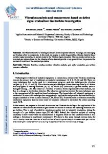
In recent years, promising results have been obtained through the use of fuel cells for small size applications. The Solid Oxide Fuel Cell (SOFC), which operates at elevated temperatures (∼ 1000◦ C) is particularly well suited for power recovery through the use of a gas turbine, in a hybrid SOFC-GT system. The potential efficiency of such a system exceeds 60% and could approach 70% for future optimised designs (Campanari, 2000; Costamagna et al., 2001; Winkler and Lorenz, 2002 and others). Most of the work performed on the modelling of such systems focuses on the fuel cell operation, using the performance characteristics of existing gas turbines. In the following we shall focus on the gas turbine, and investigate the possibility for improving the hybrid system’s performance at design and off-design operation through the use of a variance of the “variable area turbojet” concept, which includes a variable diffuser for the compressor and, if necessary, variable inlet guide vanes. SYSTEM DESCRIPTION While a large number of configurations have been suggested for SOFC-GT systems, the one usually employed in small-size applications is simple and consists of: Recuperated microturbine, usually single-shaft with constant or variable speed operation and a pressure ratio in the range of 3 ÷ 5 : 1 Fuel cell stack, producing ∼ 65 ÷ 80% of the total power. The stack temperature is typically in the 900 ÷ 1000 ◦C range. The fuel cell operates at given fuel utilization (Uf ) and air utilization (Ua ) factors. These are typically ∼ 85% and ∼ 20% respectively. The fuel cell stack replaces the burner of the microturbine. However, as Uf < 1 there is unburnt fuel that needs to be consumed. The anode and cathode exits are therefore mixed and burned, giving an additional temperature increase prior to the turbine entry. This can be performed in the fuel cell or using an external burner (Chan et al., 2003) (for the design point analysis the two are equivalent) A typical example of such a configuration is given in fig. 1. More complicated arrangements have been proposed for larger applications, including two-stage compression with intercooling (Cunnel et al., 2002), a separate free power turbine (Chan et al., 2003) or even combined cycles including water or steam (Kuchonthara et al., 1994), but these will not be considered here. The system was sized for an overall power of 200 kW. The optimum ratio between the power produced by the two engines has been examined by numerous authors (e.g. Uechi et al., 2004; Chan et al., 2002) and the results are in most cases similar to the values chosen in tbl. 1. Similarly, the gains with a pressure ratio higher than 4:1 are small, while the efficiency of the rotating components deteriorates. Fuel Cell Gas Turbine
System
Power Efficiency 145 kW (73%) ∼ 50 % 55 kW (27%) ∼ 30 %
200 kW
∼ 60 %
Geometry Typical single-stage radial compressor (4:1 Pressure Ratio) and turbine –
Table 1: Main characteristics of the proposed system
SYSTEM MODELLING In examining the performance of the gas turbine in the frame of a Solid Oxide Fuel Cell Hybrid system, the simulation of the operating characteristics of the SOFC is necessary, as the SOFC operation
2
Figure 1: Hybrid SOFC-GT system configuration
is strongly interacting with the gas turbine. For this reason, the performance of the hybrid system described is modelled using an object-oriented approach, where a model for the individual performance of each component needs to be provided, along with the “connections” between the components. The interfaces for these connections include • • • •
Fluid Flow Connections, transferring mass flow, pressure, temperature and fluid composition Mechanical Connections, transferring power and torque Electrical Connections, transferring voltage and current Signals, as an auxiliary input for some components (determining e.g. the setting of a variable blade, the opening of a valve etc.)
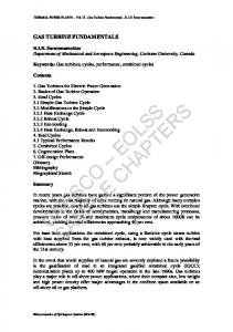
A typical connections scheme (for a compressor) is given in fig. 2. A solution for each operating point of the system is found iteratively, ensuring continuity at all the interfaces. A well established algorithm (Mor´e et al., 1980) is used for the ensuing non-linear system of equations. Modelling of the complete system requires the implementation of a number of sub-models for the various components. These connect input and output quantities, like those shown in fig. 2. The main models that needed to be implemented in this case were: • A model for the fuel cell • A model for the compressor and turbine operation • Simplified models for the other components (heat-exchangers, ducts, burner) based on prescribed efficiency and pressure loss levels. Fuel Cell Model The fuel cell operation is usually be modelled in one of two ways: 1. Either using a measured characteristic of a representative fuel cell (in the form of a V oltage − Current diagram). This corresponds to an operation at the nominal stack temperature and atmospheric pressure. Corrections are imposed for different pressure and/or temperature ((Fuel Cell Handbook, 2004; Campanari, 2000) 3
External Input IGV position
Duct
Diffuser position
Compressor
Heat Exchanger
Flow
Shaft
Mechanical Signal
Figure 2: Connections for the Compressor of the model used (the other components have more connections that are not shown)
2. Or modelling the various losses (Ohmic, activation, concentration) of the fuel cell components (anode, cathode, electrolyte, interconnection) separately, based on the operating and geometrical characteristics, as reported by Massardo and Lubelli (2000); Chan et al. (2003) and others. In both cases, the model is completed by a calculation of the heat produced/consumed in the shifting and reforming processes (Massardo and Lubelli, 2000), so that the final temperature of the gas after the fuel cell can be determined. For this work it was decided to use the second approach. A fuel cell with pre-reforming was used as the basis for the model. The main characteristics and input/output variables of the implemented configuration are given in fig. 3. Published values were used for the coefficients determining the losses (Massardo and Lubelli, 2000; Chan et al., 2003; Kakaras et al., 2003). The exact variation of losses with operating conditions depends on the actual fuel cell used, but it is expected that the overall trends will remain the same. The exact procedure for the fuel cell calculation is described in the previously mentioned publications and will not be repeated here.
Figure 3: Thermodynamic Modelling of the Fuel Cell (* denotes output quantities, the others are used as input to the model)
4
Gas Turbine Model Computationally, the gas turbine operation is modelled through the use of maps, giving the reduced mass flow (m ˙ C ), Pressure ratio (ΠC ) and isentropic efficiency (ηt−t ) for different operating speeds. When the performance data of a particular engine are not available “typical” maps can be used. For the calculation of the compressor and turbine performance of components designed for the hybrid system, a 1-D optimisation of the geometry is performed. Based on this geometry the performance maps are evaluated. Both the design and the performance estimation rely on the use of empirical correlations at this stage. While these do not accurately reproduce the performance maps, they allow the investigation of the influence of design parameters. Compressor Design and Performance Evaluation A single-stage centrifugal compressor is the obvious choice for this size and pressure ratio. The losses are modelled separately for the Impeller using the correlations developed by Galvas (1973) for the separate estimation of disc friction, blade loading, recirculation and tip clearance Diffuser using correlations based on cascade flow (Papailiou, 1974) Incidence losses for the impeller and diffuser are added for the evaluation of off-design performance. Additional losses for inlet guide vanes (when present) are evaluated as turbine blade losses (Ainley and Mathieson, 1951). Turbine Design and Performance Evaluation Similarly, a single-stage radial turbine is used. The losses are modelled using the correlations developed by Glassman (1976), Meitner and Glassman (1983) and Wasserbauer and Glassman (1975) for friction, two-dimensional, three-dimensional and tip clearance losses. Incidence losses for the nozzle guide vanes and wheel are added for the evaluation of off-design performance. For both compressor and turbine the optimum geometry is derived through an iterative method modifying the rotational speed and geometrical parameters of the components, subject to mechanical (e.g. maximum tip speed) and aerodynamic (maximum blade loading) limitations. The basic data of the components are shown in tbl. 2
RPM DS β2blade
Radial Compressor 97,000 Mass Flow 0.31kg/s 3.92 NS 0.62 37 ◦ ηt−t 83.0%
RPM DS β1blade
Radial Turbine 97,000 Mass Flow 0.32kg/s 2.92 NS 0.65 30 ◦ ηt−t 90.0%
Table 2: Main characteristics of the compressor and turbine stages
SYSTEM PERFORMANCE As a first step, typical compressor and turbine maps were used for the operation, scaled to provide the required design point characteristics. This provided an initial estimate of the rotating components effect on performance, so that the areas where improvements need to be made could be identified. The design-point performance of the gas turbine is not different from that of any microturbine. The only difference is that the level of losses between compressor exit and turbine entry is increased. As a result of this, if an existing engine is used (as opposed to one designed for the hybrid system) there will be a re-matching of the compressor/turbine pair, shifting the operating point to a non-optimal region. 5
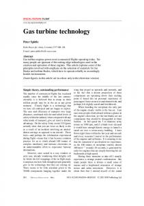
The differences are more substantial in the off-design operation. The “operating window” is controlled by three parameters (Kemm et al., 2004; Magistri et al., 2003), namely: 1. Minimum air temperature at FC inlet 2. Maximum surface temperature at FC 3. Compressor operation in surge-free region At part-load operation there may be a mismatch between the fuel cell’s air flow demands and that supplied by the compressor, leading to either over-cooling or over-heating of the fuel cell stack. The use of by-pass valves (Calise et al., 2005) or a heater/cooler (P˚alsson and Selimovic, 2001) have been suggested for increasing operating range at the expense of system efficiency. During this work we have chosen to enforce a constant TIT (thus practically constant fuel cell stack temperature) so as to maximise the performance and life expectancy of the FC. At the same time fuel utilisation (Uf ) and steam-to-carbon ratio (S/C) are kept constant (at 80% and 2.5:1 respectively) during off-design operation. Both constant and variable shaft-speed operation have been considered, and the initial results for the typical maps are shown in fig. 4. The calculations confirm that system efficiency drops rapidly when the gas turbine speed is kept constant. In all three calculations presented in fig. 3 the current drawn is reduced to 50% of the design value. In the first case (constant RPM) the operating point of the gas turbine remains unchanged, thus increasing its contribution to the system power, and dropping system efficiency. The other two cases correspond to a reduction of the rotational speed. The largest improvement is achieved when the speed decreases more (to 70%) but in this case the compressor enters the unstable operating region at part loads. 0.7
5
TIT=const, RPM 100% → 100% TIT=const, RPM 100% → 85% TIT=const, RPM 100% → 70%
4.5
0.8
4 0.84
0.65
0.82 0.8 0.76 0.78 0.72 0.74
0.6
0.55
3
ηth
ΠC
3.5
TIT=const, RPM 100% → 100% TIT=const, RPM 100% → 85% TIT=const, RPM 100% → 70%
2.5 2
0.8 0.82
0.5
0.45
1.5
0.5 0.05
0.4
0.76
1
0.1
0.15
0.2
m ˙c
0.25
0.3
0.35 80
0.35
100
120
140
160
Power (kW)
180
200
Figure 4: Compressor operating point (left) and system efficiency (right) for constant Turbine Inlet Temperature Given the obvious advantages of retaining a constant TIT, two options for achieving this without operating the compressor at or near surge were examined (or a combination of the two) 1. The use of a variable geometry compressor, so that the characteristics could be “shifted” at low speeds, increasing the surge margin. This shift can be performed through the use of IGVs (which shift the speed lines “vertically”, changing the pressure ratio at a given speed) or a variable geometry diffuser (which shifts the speed lines “horizontally”). For the latter to be effective we must ensure that the surge is controlled by the diffuser and not the inducer. 2. The use of a variable geometry turbine. This is achived through rotating NGV blades, that change the throat area, and therefore the swallowing capacity of the turbine. A change of this kind has an indirect effect on the compressor operation, influencing the point where mass flow and power balances are achieved. 6
The typical maps were replaced by those for the components designed for the application, with variable settings for the turbine IGV (±5◦ rotation of the blade), compressor vaned diffuser (±7◦ ) and compressor IGVs (±60◦ ). The first set of results (fig. 5) presents the compressor and engine performance when using variable diffuser geometry for the compressor. The two maps shown in fig. 5 (left) correspond to the initial and the final setting of the vanes (the latter map is shifted to the left). When the setting angle is allowed to vary, the “actual” map gradually shifts from the first to the second one. It is immediately obvious that the compressor behaviour differs significantly from that calculated earlier (compare with fig. 4, as in this case the part-load operation does not bring the compressor into surge for the nominal vane setting. This observation is in agreement with results reported by Hildebrandt and Assadi (2005), stating that compressors with “vertical” speed lines tend to approach surge at part-load operation, while those with “flat” speed lines suffer much less. The part-load efficiency remains practically unchanged in this configuration. The results are similar if the IGV position is changed during the deceleration (fig. 6), but in this case there is a drop in overall efficiency, as the compressor efficiency drops significantly for large deflection angles in the IGV, making this a less attractive choice. Slightly different results are obtained when using a variable turbine nozzle configuration (fig. 7), as in this case the compressor operating line can be shifted depending on the NGV setting. This allows for operation of the compressor near the optimum efficiency at part loads, resulting in an increase of the system efficiency at part-loads. 0.7
5
Fixed Geometry, RPM 100% → 75% Variable Geometry, RPM 100% → 75%
Fixed Geometry, RPM 100% → 75% Variable Geometry, RPM 100% → 75%
4.5
0.65 0.84 0.82
4
0.6 0.82
0.8
0.55 3
ηth
ΠC
3.5
0.84
0.5
2.5 0.8 0.78 0.76
0.45
2 0.74 0.72
1.5
1 0.05
0.1
0.15
0.2
0.4
0.25
m ˙c
0.3
0.35
0.4
0.35 90
0.45
100
110
120
130
140
150
160
170
Power (kW)
180
190
200
Figure 5: Compressor operating point (left) and system efficiency (right) for constant Turbine Inlet Temperature with variable geometry compressor (Change in Vaned Diffuser Setting)
CONCLUSIONS The calculation results indicate that the performance of a hybrid SOFC-GT system can be improved when a gas turbine specifically designed for operation in such a system is used. More specifically 1. A fixed geometry compressor with a sufficiently wide operating range may allow operation of the fuel cell at constant temperature without surge problems. Use of an existing microturbine will result in suboptimal performance, as the increased pressure losses of the hybrid system will resulting in a re-matching of he compressor and turbine. 2. The prediction of surge on a 1-D basis is not really reliable, and the actual surge margin may be smaller than the predicted one. In that case use the use of variable geometry components will be an interesting alternative. 3. Even if there are no problems with surge, better part-load efficiency can be achieved with variable geometry components, as the compressor operating line is kept near maximum efficiency 7
0.7
5
Fixed Geometry, RPM 100% → 75% Variable Geometry, RPM 100% → 75%
Fixed Geometry, RPM 100% → 75% Variable Geometry, RPM 100% → 75%
4.5
0.65 0.84 0.82
4
0.6 0.82
0.8
0.55 3
ηth
ΠC
3.5
0.84
0.5
2.5 0.8 0.78 0.76
0.45
2 0.74 0.72
1.5
1 0.05
0.1
0.15
0.4
0.2
0.25
0.3
0.35
m ˙c
0.4
0.45
0.35 90
0.5
100
110
120
130
140
150
160
170
Power (kW)
180
190
200
Figure 6: Compressor operating point (left) and system efficiency (right) for constant Turbine Inlet Temperature with variable geometry compressor (Change in IGV Setting) 0.7
5
Fixed Geometry, RPM 100% → 75% Variable Geometry, RPM 100% → 75%
Fixed Geometry, RPM 100% → 75% Variable Geometry, RPM 100% → 75%
4.5
0.65 0.84 0.82
4
0.6 0.82
0.55 3
ηth
ΠC
3.5
0.8
0.84
0.5
2.5 0.8 0.78 0.76
0.45
2 0.74 0.72
1.5
1 0.05
0.1
0.15
0.2
0.4
0.25
m ˙c
0.3
0.35
0.4
0.35 80
0.45
100
120
140
160
Power (kW)
180
200
Figure 7: Compressor operating point (left) and system efficiency (right) for constant Turbine Inlet Temperature with variable geometry turbine
at all conditions. If a fixed geometry is used the operating line is fixed by the TIT demand. The use of variable geometry may also benefit in solving problems with the transient operation of the hybrid system, which is quite different from that of a simple gas-turbine, as it provides additional degrees of freedom for the operation of the engine. 4. The use of a variable nozzle turbine appears to be the most attractive option, giving increased part-load efficiency. Further work will be performed for the detailed design of a variable NGV turbine and a variable diffuser compressor. The variable IGV solution will not be pursued at this point, as the loss in compressor efficiency seems to overcome potential benefits. ACKNOWLEDGEMENTS The authors wish to thank the European Commission and their partners in the project FELICITAS (which was co-funded by the European Union within the Sixth Framework Programme) for their help and support. REFERENCES Fuel Cell Handbook. U.S. Dept. of Energy, 7th edition, 2004.
8
Ainley, D. and Mathieson, G. A Method of Performance Estimation for Axial Flow Turbines. R&M 2974, British Aeronautical Research Council, London, 1951. Calise, F., Palombo, A., and Vanoli, L. Design and partial load exergy analysis of hybrid SOFC-GT power plant. Journal of Power Sources, ?:xxx–xxx, 2005. Campanari, S. Full Load and Part-Load Performance Prediction for Integrated SOFC and Microturbine Systems. Journal of Engineering for Gas Turbines and Power, 122(2):239–246, April 2000. Chan, S. H., Ho, H. K., and Tian, Y. Modelling of Simple Solid Oxide Fuel Cell and Gas Turbine Power Plant. Journal of Power Sources, 109:111–120, 2002. Chan, S. H., Ho, H. K., and Tian, Y. Modelling for Part-Load Operation of Solid Oxide Fuel Cell-Gas Turbine Hybrid Power Plant. Journal of Power Sources, 114:213–227, 2003. Costamagna, P., Magistri, L., and Massardo, A. F. Design and part-load performance of a hybrid system based on a solid oxide fuel cell reactor and a micro gas turbine. Journal of Power Sources, 96:352–368, 2001. Cunnel, C., Pangalis, M. G., and Martinez-Botas, R. F. Integration of solid oxide fuel cells into gas turbine power generation cycles. Part 2: hybrid model for various integration schemes. Proc Instn Mech Engrs Part A: Journal of Power and Energy, 216:145–154, 2002. Galvas, M. R. FORTRAN Program for Predicting Off-Design Performance of Centrifugal Compressors. Technical Note TN D-7487, NASA, Lewis Research Center, 1973. Glassman, A. J. Computer Program for Design Analysis of Radial Inflow Turbines. Technical Note TN D-8164, NASA, Washington, 1976. Hildebrandt, A. and Assadi, M. Sensitivity Analysis of Transient Compressor Operation Behaviour in SOFC-GT Hybrid Systems. In Proceedings of ASME Turbo Expo 2005, number GT2005-68744, Reno-Tahoe, Nevada, USA, 2005. Kakaras, E., Panopoulos, K. D., Fryda, L., Perdikaris, N., Pilidis, P., Diacakis, M., and Dominguez, A. Thermoeconomic Analysis of a SOFC Based Tri-Generation System. In Proceedings of ECOS 2003, Copenhagen, Denmark, 2003. Kemm, M., Hildebrandt, A., and Assadi, M. Operation and Performance Limitations for Solid Oxide Fuel Cells and Gas Turbines in a Hybrid System. In Proceedings of ASME Turbo Expo 2004, number GT2004-53898, Vienna, Austria, 2004. Kuchonthara, P., Bhattacharya, S., and Tsutsumi, A. Combinations of solid oxide fuel cell and several enhanced gas turbine cycles. Journal of Power Sources, 49:333–348, 1994. Magistri, L., Bozzo, M., Tarnowski, O., Agnew, G., and Massardo, A. F. Design and Off-Design Analysis of a MW Hybrid System Based on Rolls-Royce Integrated Planar SOFC. In Proceedings of ASME Turbo Expo 2003, number GT2003-38220, Atlanta, Georgia, USA, 2003. Massardo, A. F. and Lubelli, F. Internal Reforming Solid Oxide Fuel Cell-Gas Turbine Combines Cycles (IRSOFC-GT): Part A–Cell Model and Cycle Thermodynamic Analysis. Journal of Engineering for Gas Turbines and Power, 122(1):27–35, January 2000. Meitner, P. L. and Glassman, A. J. Computer Program for Off-Design Performance Analysis of Radial Inflow Turbines with Rotor Blade Sweep. Technical Paper 2199, NASA, 1983. Mor´e, J., Garbow, B., and Hillstrom, K. User Guide for MINPACK-1. Report ANL-80-74, British Aeronautical Research Council, Argonne, 1980. P˚alsson, J. and Selimovic, A. Design and Off-Design Predictions of a Combined SOFC and Gas Turbine System. In Proceedings of ASME Turbo Expo 2001, number 2001-GT-0379, New Orleans, Louisiana, USA, 2001. Papailiou, K. D. Correlations Concerning the Process of Flow Deceleration. In Proceedings of ASME Turbo Expo 1974, number Paper ASME 74-GT-87. ASME, 1974. 9
Uechi, H., Kimijima, S., and Kasagi, N. Cycle Analysis of Gas Turbine–Fuel Cell Hybrid Micro Generation System. Journal of Engineering for Gas Turbines and Power, 126(4):755–762, October 2004. Wasserbauer, C. A. and Glassman, A. J. FORTRAN Program for Predicting Off-Design Performance of Radial-Inflow Turbines. Technical Paper TN D-8063, NASA, Washington, 1975. Winkler, W. and Lorenz, H. The design of stationary and mobile solid oxide fuel cell–gas turbine systems. Journal of Power Sources, 105:222–227, 2002.
10