it possible to suppress the "flute" instability,4 which is known to plague "classical" axisymmetric mirrors. Stability against this magnetohydrodynamic (MHD) mode ...
JOURNAL OF PROPULSION AND POWER Vol. 11, No. 3, May-June 1995
Gasdynamic Fusion Propulsion System for Space Exploration Terry Kammash* and Myoung-Jae Leet University of Michigan, Ann Arbor, Michigan 48109 An open-ended fusion system in which a high-density plasma is confined and heated to thermonuclear temperatures is examined as a potential high specific power propulsion device that can be used for space exploration. With a collision mean free path much smaller than a characteristic dimension of the system, the plasma behaves much like a continuous medium (fluid) for which the confinement time is drastically different from that which characterizes a typical fusion power reactor. Noting that fact and using an appropriate set of balance equations we derive an expression for the length of the rocket in terms of the plasma parameters required for certain propulsive capabilities. We find that a moderately sized system can produce large values of specific impulse and thrust that would allow a massive rocket to make a round-trip to Mars in months instead of years. By carrying out a preliminary engineering design we also identify those technological areas that must be developed before such a system can become practical. Many of these technologies are surprisingly not out of reach today.
Nomenclature central region area mirror cross-sectional area; nozzle area magnetic field in plasma vacuum magnetic field engineering design safety factor velocity of light c constant defined in Eq. (9) c() one-way linear distance ( = Dab, Dba) D E electron energy in Eq. (19) Ein injection energy escape energy EL magnet stored energy Es energy produced by fusion E(} thrust F Earth's gravitational acceleration specific impulse / current density constant defined in Eq. (9) k L length of rocket magnet mass Mm radiator mass Mrad refrigerator mass Mref shield mass Ms Mtot total mass ( = Mm + Mrad + Mref + M,) m ion mass = m mh dry mass of vehicle mf initial mass of vehicle ra, mass of propellant used in traveling from b to a ra/p" rest mass of electron m() factor defined in Eq. (16) N plasma density bremsstrahlung power fusion power Pin injected power PR plasma pressure synchrotron radiation power Ps reactor gain factor Q q ion charge R plasma mirror ratio reflection coefficient Re
Ac A(] Bp Bp(} Cm
R() rM rm rp rs r,t., ry r() r,, r2 S T UB Vm v v th Wf a, a* /3
= = = = = = = = = = = = = = = = =
y 8 6 A //,„ pi pm p, T T RI as o> (crv) o)ci
= = = = = = = = = = =
=
= =
vacuum mirror ratio mirror (throat) radius in Fig. 1 radius to magnet in Fig. 1 plasma radius in Fig. 1 radius to outer wall of shield in Fig. 1 inner and outer radii of shield in Fig. 1 classical electron radius inner and outer radii of conductor injection rate per cm3 plasma temperature magnetic energy density volume enclosed by magnetic field velocity thermal velocity dry weight of vehicle mass ratios defined in Eqs. (26-30) ratio of plasma pressure to magnetic field pressure ratio of specific heats fraction occupied by J loss cone angle collision mean free path magnetic permeability ion Larmor radius magnet mass density structure density confinement time round-trip travel time stress in structure Thompson cross section velocity averaged fusion cross section ion gyrofrequency
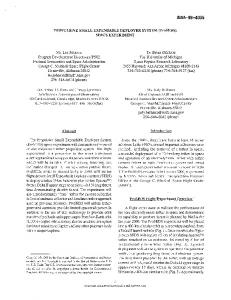
Introduction NE of the most critical ingredients of a manned mission to the planet Mars is a propulsion system that can make the trip in a relatively short time to minimize physical degradation and exposure to hazardous galactic radiation by the crew. The device we consider in this article is such a system, and consists of a solenoid around which a current-carrying conductor is wound to generate a "simple mirror" magnetic geometry in which a hot plasma is confined and allowed to undergo fusion reactions. The system, shown in Fig. 1, is maintained in steady state by injection of particles in the region of the homogeneous magnetic field to effectively balance the plasma loss through the mirrors, where the magnetic field is stronger than it is at the center. If we denote by R0
O
Received Oct. 8, 1993; revision received April 14, 1994; accepted for publication Aug. 26, 1994. Copyright © 1994 by the American Institute of Aeronautics and Astronautics, Inc. All rights reserved. *Professor of Nuclear Engineering. Associate Fellow AIAA. tGraduate Student in Nuclear Engineering. 544
KAMMASH AND LEE:
Magnetic Field Line
It follows therefore that EL = 2T
Area: Ac
Area: Length L
Fig. 1 Schematic and cross-sectional view of the gasdynamic fusion propulsion system.
the ratio of the vacuum field at the mirror to that at the center, then as a propulsion system asymmetry in the mirror ratios must be imposed in order to minimize losses through the mirror that will not be used as a nozzle. In fact, for a device with a large aspect ratio (L » rp), the magnetic configuration is effectively that of a "meridional" nozzle,1 which is azimuthally symmetric in that the fluid flow velocity is everywhere parallel to the magnetic field lines. In contrast to a conventional mirror fusion reactor where a typical fuel ion will traverse the device several times before it undergoes a scattering collision,2 the plasma in the propulsion system will be sufficiently dense so that A will be significantly smaller than a characteristic dimension of the system, i.e., the plasma will behave much like a continuous medium—a fluid. Under these circumstances the escape of the plasma from the system is analogous to the flow of a gas into a vacuum from a vessel with a hole. The plasma "flux" across the mirror cross section A() can be estimated as A0nvth, By dividing the total number of particles in the system, AcnL (Ac is the cross-sectional area of the plasma in the central region) by the flux we can find the particle lifetime in the device to be r ~ (AcL/A0vtlt) =
(1)
where R (related to R(}) is the mirror ratio seen by the plasma. A more accurate derivation of the confinement time and the mean energy EL of an escaping ion can be obtained by noting that the velocity distribution of the particles in a fluid is Maxwellian, hence,
r
VS \277
Jo RL
^P-T dv (2)
RL E, 4 / m \ ~ f* mv 5 7i —~ = —— I — I I —— ^ ~ r
545
GASDYNAMIC FUSION PROPULSION SYSTEM
VTT \2r/
Jo 2/?L
2T
27V th jRL
8T_
RL V irm
(3)
(4)
In contrast with the classical mirror where A » L, the lifetime is a linear, rather than a logarithmic, function of R. Consequently, in a gasdynamic confinement system, increasing the mirror ratio to the highest value permitted by the technology provides a much greater effect than in a classical mirror. For reasons that will become clear shortly, in this article we consider systems for which R » 1. It might be added at this point that when R » 1, the estimate given by Eq. (1) is valid when X/R « L, which is much less stringent than the condition A « L. In other words the quantity to be compared with the length of the device L is not the mean free path A, but an effective mean free path against scattering through an angle of the order of the "loss cone" angle 6 ~ I/Vx. This angle represents a region in velocity space, which if a particle falls in it as a result of a Coulomb collision with another particle, it will definitely escape through the end. Under these conditions, any loss cone instability 3 arising from depletion of the velocity distribution function will not have an important effect on the longitudinal confinement time. Any reduction in the scattering length cannot cause a significant change in the rate at which the plasma is lost through the mirrors; thus, it cannot lower the lifetime below the value given in Eq. (1) or (2). In our assessment of this system as a propulsion device we must, however, strike a balance between its confinement capability as reflected in its ability to produce fusion energy to heat the fuel, and its propulsive capability as reflected in its ability to eject energetic particles through the mirror nozzle. Another important feature of this system is the high plasma density in the region just beyond the mirror where it is comparable to that at the center of the system. This feature makes it possible to suppress the "flute" instability, 4 which is known to plague "classical" axisymmetric mirrors. Stability against this magnetohydrodynamic (MHD) mode and the loss cone microinstability alluded to above, provide an added dimension to the utility of this concept as propulsion device. In other words, there seems to be no serious plasma oscillation problems that could endanger the performance of the gasdynamic mirror as a propulsive system while it produces the fusion energy needed to heat its fuel (propellant). Moreover, since the presence of the plasma anywhere in the device reduces the magnetic field at that point, it follows that R seen by the plasma can be expressed in terms of R(} by (5)
where
Bp = Bp()
(6)
and Bp(} is the vacuum field at the center. The quantity /3 is a measure of how effective the magnetic field is in confining the plasma, and its value is very sensitive to the MHD stability raised earlier. The more stable the system is against these modes, the higher beta value that can be sustained, and in turn, the higher the fusion power density that can be supported by the system. In order to fully assess the performance of the gasdynamic mirror propulsion system, we must first establish the dynamics of the plasma it contains. Furthermore, we will carry out a preliminary engineering design in order to identify the critical areas of research and development that must be addressed before such a system can become operational. Moreover, such consideration allows us to assess the impact of confinement physics on the sizes and masses of these components as well as the demands placed on their performance capabilities. No attempt will be made to provide detailed or optimized design
546
KAMMASH AND LEE:
GASDYNAMIC FUSION PROPULSION SYSTEM
of these parts since the technology in many instances may be viewed as still evolving. The physics model we employ is somewhat simplified in that we use one ion species to represent the deuterium-tritium (D-T) (50-50% mixture) ions with an average mass of 2.5 atomic mass units, and ignore the dynamics of the electron component of the plasma as well as the alpha particles generated by the D-T fusion reactions. We shall assume a high ft operation of the system arising from a large degree of plasma stability; that in turn allows us to assess the impact of reduced synchrotron radiation losses, especially in cases where high reflectivity Re walls are assumed. Under these conditions the equations of interest reduce to the steady-state mass conservation equation S - (nlr) - (n2l2)((iv} = 0
(7)
and the steady-state power (energy) balance equation SE-m + (n-l*)(av)E() - (nEJr) - Ph - Ps = 0
(8)
In these equations S is the rate of injection of fuel ions per unit volume, (av) the velocity-averaged fusion reaction cross section, Ein the energy of the injected particle, E0 the energy produced by a D-T fusion reaction (17.6 MeV), Ph the bremsstrahlung radiation power, Ps the synchrotron radiation power and EL the mean energy of an escaping ion. We recall from Eq. (4) that such an ion leaves with an average energy equal to twice the thermal energy of a confined ion. It is convenient to express many of the terms in the conservation equations explicitly in terms of the temperature, i.e., to write B2p()ft
16777
=
B|o
.
=
1677
kT"
(9) P h
= n 77 2 T 1/2 = ^
Ps = s()n2T2 = 0
P
r
r-j/2
k2 V /? 4 ^O^pO
k2
where p{] = 3.34 x 10~ l5 keV172 cm3/s and s0 is given by Eq. (20). The quantity (ov) is also temperature-dependent, but since this dependence varies in different temperature regimes, it will be left in its standard form until numerical evaluations are called for. If we solve for S from Eq. (7) and substitute the result in Eq. (8) we obtain an expression for the plasma (device) length as a function of temperature, i.e., =
~ B2(]c(}R[p()
kT(E,n - 27) + s0T*2 - i(2£in + E0)T~^]
(10)
which upon insertion of the first of Eq. (9) becomes
L =
(£in - 2T) nc()R[p()
(11)
The value of E-m can be established by first noting that the injection power Pm can be expressed in terms of Pf through m ~ 3 "HC'I m ~ 3 T, keV L, m rM, m V m Halo thickness, m Shield thickness, m Shield-magnet gap, m *„«, T E v , GJ v thi , m/s v thc , m/s Vth.cff, m/s F, N ' /V.,t, MW P,, MW F/,, MW Fs, MW P,,, MW Neutron wall load, MW/m 2 Surface heat flux, MW/m 2 /, MA/m 2 M;|J, mg
I 15
10 = 0.95 R = 50 Re = 90% T. = 20 keV TV, = 1 cm IxlO1
IxlO11
IxlO1'
IxlO1'
1
Q ft
Plasma Density n (cm'3)
Fig. 11 Variation of rocket specific power with density for different magnet mass calculation. 800 D-T Fusion 700 600
MraiH
m
§
M rc( , mg M v , mg M tot , mg
500
a cll , kW/kg 400
/sp.eff'
S
300
2800 D-T Fusion
200
2600
Magnet Virial Theorem
100
J = 250 MA/m2
0
0.1
0.2
0.3
0.4
0.5
0.6
0.7
Re = 90% L = 37.1m T = 15 keV 7i = 1016 cm'3
2400 0.8
0.9
2200
1
J = 50 MA/m2
2000
Plasma Beta p
Fig. 12 Variation of magnet mass with plasma beta.
atures are used since they lead to larger neutron and radiation power. In fact, system 1 at a nozzle radius of 1 cm and almost present-day magnet technology should be especially suitable for a manned Mars mission, even though it requires a few more days than the other systems where technological demands are clearly more stringent. The relevant design parameters of that system are given in Table 2. Figure 11 further confirms the suitability of a propulsion system with a nearterm technology, since it produces about the same specific power at n = 1016 cm" 3 as the more advanced systems. All these results were obtained using a beta value of 0.95, which might be viewed as optimistic. It may be argued that a high degree of plasma stability may not be achievable, and hence, a more modest value of beta must be employed in assessing the performance of the rocket. We note from Eq. (6) that the vacuum magnetic field required to confine the plasma becomes larger at a smaller /3, and that in turn means a more massive magnet. Clearly, that also means a larger total mass, and in an effort to assess the sensitivity of these quantities to /3 we have generated the results given in Figs. 12 and 13, in which the variations of the magnet mass and total mass with /3 are displayed, respectively. We note in both instances
i
1800
__ J = 250 MA/m2
1600
Magnet Virial Theorem
1400 1200 1000 0
0.1
0.2
0.3
0.4
0.5
0.6
0.7
0.8
0.9
1
Plasma Beta p
Fig. 13 Variation of total mass with plasma beta.
that the mass does not change dramatically for beta values larger than about 0.35, especially in the case of the superconducting magnets characterized by the high current density and the virial theorem. The variation is even less dramatic in the case of the total mass due to the fact that the magnet constitutes but a small fraction of all the components that make up the rocket dry mass. The sensitivity of travel time to ft is given in Table Ib where the plasma parameters of Table 2 were used in obtaining the results shown. We readily note that less than 4% reduction in travel time is obtained
552
KAMMASH AND LEE: GASDYNAMIC FUSION PROPULSION SYSTEM
technology (as given in Table la) may be prohibitively large, especially if it is to be assembled in space. We have, therefore, re-examined the governing equations of the system to see if other operating conditions might exist that could result in a more modest mass for the vehicle. The results presented earlier were chosen because they yielded the shortest length (as may be noted from the plots given in the text) without regard to the associated mass. If we do not insist on these plasma conditions that yield the smallest "L," and re-examine Eq. (11) to see if there exist other conditions that result in a significant reduction on the total mass, then the results given in Table 4 will emerge. These results reveal, in effect, the sensitivity of the total vehicle mass to the various plasma parameters that underlie the rocket performance. System 1 gives a summary of the relevant characteristics that result in minimal length, for mirror ratios of 50 and 100, whereas system 2 reflects an attempt to produce the smallest possible total mass without regard to the length. It should be noted that the results for system 2 were obtained without changing the previously used performance characteristics of the various components such as the radiator, shield, etc. We see that the rocket length increased substantially for system 2, whereas the confining magnetic field became smaller by almost a factor of 3. If we use the advanced magnet technology as the basis for computing the mass of this component we find that the total rocket mass is reduced to 400 and 295 mg for mirror ratios of 50 and 100, respectively. When compared to system 1, the thrust in system 2 is smaller due to the lower plasma density and temperature, and that in turn results in smaller thrust power and rocket specific power, although the latter quantity is still considered quite attractive at 11 and 14. If we apply these results to the Mars mission described earlier we find that the round-trip time has increased somewhat, but remains quite short compared to other propulsion systems. In short, this limited sensitivity study reveals that a more manageable rocket mass can indeed be attained with the gasdynamic mirror propulsion system, and there is no reason to believe that it cannot be reduced further if advances in radiator, shield, refrigerator, etc., technology are also achieved. As can be seen from Table 4, these reductions are feasible without seriously diminishing the propulsive capability of the system.
when the /3 value is nearly tripled (from 0.35 to 0.95). These differences will be even less distinguishable when advanced magnet technology is utilized. Current fusion experiments do make use of conventional cables that carry about 5 kA/cm2 (i.e., 50 MA/m2) in generating the magnetic fields utilized in confining the hot plasma. Some international devices (e.g., Tore Supra in France) are currently experimenting with the use of superconducting magnets for plasma confinement, and the likelihood of achieving very high current densities in the not too distant future does not appear unrealistic. It has often been argued that better propulsion performance can be obtained if the D-T fuel is replaced by deuteriumhelium (D-He3) because of the significant reduction in neutron power, and correspondingly in radiator mass. Whereas neutron power constitutes about 80% of fusion power in DT reactions, it constitutes about 5% in D-He3 reactions, and such reduction should alleviate considerably problems associated with disposal of this heat component. The D-He3 reaction itself does not produce neutrons, but the satellite reactions involving D do indeed produce neutrons, though to a lesser extent. These favorable aspects of D-He3 reactions are, however, offset by the high ignition temperature required by this fuel cycle, and the corresponding large amount of synchrotron radiation emitted. For purposes of comparison we carried out analysis of system 1 (in Table la) for a D-He3 fuel cycle at an operating temperature of 100 keV and the same plasma density of 1016 cm~ 3 . The results are summarized in Table 3. We note immediately that the rocket length increased from 32 m to a prohibitive length of about 2858 m, the confining magnetic field more than doubled, and even the neutron power more than tripled due to the significant increase in plasma volume. For the same reflection coefficient of 90% the synchrotron radiation power in the D-He3 case is over 2000 times larger than its counterpart in the D-T case, resulting in a total propulsion mass that is well over 50 times larger. Because of the high temperature in the D-He3 rocket, the specific impulse is about 2.5 times larger than its value in the D-T case, and the thrust is about 7 times larger, but because of the overwhelmingly larger total mass, the Mars mission will take three times as long to accomplish. If superconducting magnet design as reflected by magnet virial theorem is employed in place of present or near-term technology (/ = 50 MA/m2), the Mars mission travel time will be reduced by about 27%. In both instances, however, the specific power of the propulsion device is considerably smaller than its counterpart in the D-T case. In fact, even if the synchrotron radiation is totally neglected, the specific power in the D-He3 case becomes comparable to that of D-T for present day magnet technology, but almost doubles if advanced technology is utilized.
Summary and Conclusions We have proposed and analyzed, in this article, a propulsion device with potentially attractive propulsive capabilities that, if realized, would lead to relatively short interplanetary travel times. It is based on the simple magnetic mirror fusion configuration that has been investigated extensively for decades for terrestrial power applications. Unlike those mirrors, however, where the plasma density is sufficiently low to be considered "collisionless," the proposed concept would contain a significantly higher density to justify identifying it as a highly collisional or a "gasdynamic" mirror in which the collision mean free path is considerably shorter than the length of the
Sensitivity to Rocket Mass Because of the economics of putting objects in space it is clear that a total mass of 1847 mg using present day magnet technology (see Table 2) or even 1611 mg using future magnet
Table 4 Sensitivity of rocket performance to total mass System 2
System 1 Parameter Rocket length, m Plasma density, cm~ 3 Plasma temperature, keV Magnetic field, T Thrust, N Total mass,a mg Specific impulse, s Specific power, kW/kg TRT to Mars, days :
'Using advanced magnet technology.
R = 50
R = 100
R = 50
R = 100
31.73 1 x 10¹⁶ 15 11.28 2.52 x 10⁴ 1611 1.58 x 10⁵ 24 106
15.87 1 x 10¹⁶ 15 11.28 2.52 x 10⁴ 1589 1.58 x 10⁵ 11 105
213 2 x 10¹⁵ 10 4.12 3.36 x 10³ 400 1.29 x 10⁵ 11 143
107 2 x 10¹⁵ 10 4.12 3.36 x 10³ 295 1.29 x 10⁵ 14 124
KAMMASH AND LEE:
GASDYNAMIC FUSION PROPULSION SYSTEM
system. Under these conditions plasma confinement is characterized by a confinement law that is drastically different from that which describes the collisionless mirror. Although, in the past, several authors considered the simple mirror machine as the engine of a hypothetical rocket, the results obtained are totally unrelated to those presented here since a collisionless mirror was used as the basis of their study. We have seen that in the gasdynamic mirror rocket, large aspect ratio engines are desirable because of the associated better confinement that leads to a more efficient production of fusion energy, and the large degree of plasma stability that results in a more efficient utilization of the confining magnetic field. This is reflected in the high p value used in the analysis, which in turn resulted in relatively small magnet masses. However, as noted in this study, the magnet mass and, in turn, the total mass of the vehicle does not vary significantly over a wide range of fi values, with the result that the travel time is hardly affected. Three magnet designs were examined, ranging from present day (or near-term) technology that utilizes windings that carry 50 MA/m2, to an advanced (superconducting) technology that allows for much higher current densities. When applied to a round trip Mars mission that utilizes a continuous burn acceleration/deceleration trajectory profile, it is shown that a rocket that uses present day magnet technology can still make the round-trip in months instead of years. An elementary design was also carried out in order to identify the major components of the system, their masses, and the demand placed on their performance capabilities. It is shown that next to the magnet mass the radiator mass constitutes the major portion of the total vehicle dry mass based on an assumed radiative capability of 5 MW/mg. When a DT fuel is used to produce the fusion energy needed to propel the rocket, reasonable plasma and engineering parameters are found to characterize the system. For example, a magnetic field strength of about 11T is shown to be adequate for plasma confinement, and that is slightly higher than (—10 T) the fields utilized in some present-day fusion experiments. In spite of the large vehicle mass of a DT-driven rocket, the thrust power generated is sufficiently high to produce an acceptable, if not an attractive, specific power.
553
A rocket that utilizes the D-He3 fuel cycle was also examined in order to study the impact of an aneutronic (producing no neutrons) fuel on the performance of the rocket. A certain fraction of the fusion power did nevertheless appear in the neutrons due to the satellite reactions involving the deuterium, though to a much lesser extent. But because of the drastic increase in the operating temperature and size of the rocket, the total mass of the system increased dramatically over that of the D-T rocket, and the technological development demands of most of the components are so severe that realization of such a system in the foreseeable future appears to be at best remote.
Acknowledgment This work was supported in part by the U.S. Department of Energy.
References 'Gerwin, R. A., et al., "Astronautics Laboratory Report," ALTR-89-092, Feb. 1990. 2 Kammash, T., Fusion Reactor Physics—Principles and Technology, Ann Arbor Publishers, Ann Arbor, MI, 1975, Chap. 4. 3 Post, R. F., Nuclear Fusion, Vol. 27, 1987, p. 1579. 4 Nagornyj, V. P., Ryutov, D. D., and Stupakov, G. V., Nuclear Fusion, Vol. 24, 1984, p. 1421. 5 Hilton, J. L., Luce, J. S., and Thompson, A. S., "A Hypothetical Fusion Propulsion Rocket Vehicle," AIAA Paper 63-239, June 1963; also Hilton, J. L., IEEE Transactions on Nuclear Science, Vol. NS10, No. 1, 1963, p. 153. 6 Kilcrease, D. P., and Kirkpatrick, R. C., Nuclear Fusion, Vol. 28, 1988, p. 1465. 7 Santarius, J. F., and Logan, B. G., AIAA Paper 93-2029, June 1993. 8 Dolan, T. J., Fusion Research, Technology, Vol. Ill, Pergamon, New York, 1980. y Kammash, T., 44th Congress of the International Astronautical Federation, IAF-93-S.3.472, Graz, Austria, Oct. 1993. 1() Borowski, S. K., "A Comparison of Fusion/Antiproton Propulsion Systems For Interplanetary Travel," AIAA Paper 87-1814, June 1987.


![[PDF] Deep Space Propulsion - Google Sites](https://m.moam.info/img/260x300/pdf-deep-space-propulsion-google-sites_64777251097c4796708bb603.jpg)