Universitat Rovira i Virgili. Carretera de Salou s/n. 43006 Tarragona, Spain. ** Departament d'Enginyeria Electrònica. Escola Tècnica Superior d'Enginyers de.
General Purpose Sliding-Mode Controller for Bidirectional Switching Converters Alfonso Romero*, Luis Martínez-Salamero*, Hugo Valderrama*, Oscar Pallás** and Eduardo Alarcón** * Departament d’Enginyeria Electrònica, Elèctrica i Automàtica. Escola Tècnica Superior d’Enginyeria. Universitat Rovira i Virgili Carretera de Salou s/n 43006 Tarragona, Spain
** Departament d’Enginyeria Electrònica. Escola Tècnica Superior d’Enginyers de Telecomunicació. Campus Nord - Mòdul C-4. C/. Gran Capità s/n 08034 Barcelona, Spain.
Proceedings of the IEEE International Symposium on Circuits and Systems (ISCAS98), Monterey, California, USA, May 31- June3,1998.
1998 IEEE. Personal use of this material is permitted. However, permission to reprint or republish this material for advertising or promotional purposes or for creating new collecting works for resale or redistribution to servers or lists, or to reuse any copyrighted component of this work in other works must be obtained from the IEEE. This material is presented to ensure timely dissemination of scholarly and technical work. Copyright and all rights therein are retained by authors or by other copyright holders. All persons copying this information are expected to adhere to the terms and constraints invoked by each author's copyright. In most cases, these works may not be reported without the explicit permission of the copyright holder.
GENERAL PURPOSE SLIDING-MODE CONTROLLER FOR BIDIRECTIONAL SWITCHING CONVERTERS Alfonso Romero*, Luis Martínez-Salamero*, Hugo Valderrama*, Oscar Pallás** and Eduardo Alarcón** *
Departament d’Enginyeria Electrònica, Elèctrica i Automàtica. Escola Tècnica Superior d’Enginyeria. Universitat Rovira i Virgili Carretera de Salou s/n 43006 Tarragona, Spain
** Departament d’Enginyeria Electrònica. Escola Tècnica Superior d’Enginyers de Telecomunicació. Campus Nord - Mòdul C-4. C/. Gran Capità s/n 08034 Barcelona, Spain. ABSTRACT A standardized sliding- mode contoller for bidirectional switching converters is described. The proposed circuit is suitable for large-signal applications and can be used in a large class of dc-to-dc switching converters. As a result, robustness and fast dynamic response against supply, load and parameter variations is obtained. The controller implementation has been performed by means of standard operational amplifiers (OA’s) and it has been tested experimentally in elementary and complex switching power converters. An integrated realization of the controller has been simulated at transistor level by means of HSPICE exhibiting similar characteristics to those presented by the OA’s-based implementation. 1. INTRODUCTION The solution of the control problems in dc-to-dc switching converters has been traditionally undertaken by means of conventional techniques based on the linearization of the converter bilinear model. These techniques are based on a linear low frequency characterization of the switching converter so that frequency-domain design methods can be applied to solve the control problem. The controller design following that approach can be specially difficult if the converter has several poles and one or more right half plane zeroes. In addition, the low frequency small-signal model cannot predict the large-signal behavior or the stability of the system. On the other hand, there are large-signal control techniques [1] which have provided excellent performances in bidirectional converters, their application having led to the generation of different types of power waveforms in the converter output and opened the way to new designs of power amplifiers and sinusoidal inverters. These techniques are based on a nonlinear discrete-time recurrence obtained through the integration of the converter state equations along the switching period and the subsequent introduction of the control constraints. An alternative approach based on the application of variable structure theory and the associated sliding regimes has been developed in the last years [3] - [4]. The sliding-mode control is a time-domain technique suitable for large-signal
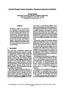
applications exhibiting low sensitivity to external perturbations and parameter variations. We describe in this paper the main characteristics of a general purpose sliding-mode controller which can be used to regulate a large class of switching converters. Namely, buck, boost, buck-boost, Cuk, buck with input filter, boost with output filter and SEPIC converter. 2. O.A.’S - BASED STANDARIZED MODULE It has been shown in the last years [ 2 ] - [ 5 ] that linear combinations of state variables used as sliding surfaces provides stable equilibrium points in second a fourth order converters. The simplicity of the control law for a large family of converters is exploited in this paper to implement a generalpurpose controller of the type shown in Fig. 1
xn Vg
dc-to-dc
x2
switching converter
x1 PULSE AMPLIFIER
+
u u S
S
K1 K2 Kn
+
_ _ x1 * x2 *
+ _
xn*
Fig.1 Block diagram of the generalized sliding-mode controller The practical implementation of the controller requires three different stages. Namely, input stage for measuring converter floating signals or referred to ground, stage for generation of the sliding surface and output stage based on a hysteretic comparator with buffer circuits. The input stage consist of several differential structures of the type shown in Fig.2. The resistances of the circuit are choosen to implement the coefficients of the sliding surface. Voltage
Vref is required to generate the error signal associated to the state variable measured by the first differential amplifier. The differential structure of Fig.2 is repeated for each converter variable needed in the generation of the sliding surface.
Z V+
1
I
R
V+ V-
1
VVref Fig 2. Basic differential structure in the input stage. The second stage implements the sliding surface that will eventually be used in the converter control. It uses the outputs of the first stage to make linear combinations of them by means of operational amplifiers. Therefore, the expression of the voltage at the output of the second stage will be of the form: S(x)=K1(x1-x1*)+...+Kn(xn-xn*), where K1,..., Kn are the sliding surface coefficients, x1,..., xn are the converter variables and (x1-x1*),...,(xn-xn*) are the state variable errors. The surface uses up to four state variables and admits the inclusion of a compensating network [ 8 ]. The third stage is a hysteretic comparator implemented by means of an operational amplifier with positive feedback. The hysteresis width can be externally controlled and the corresponding output signal is a square wave. To obtain a binary signal that activates/ deactivates the converter switch, two buffer circuits are added to the comparator output in order to adjust the power level of the comparator output to the required level in the converter input. 3. INTEGRATED APPROACH. The integrated version of the controller has been designed at transistor level with 0.8 µm CMOS technology and has been performed at simulation level by means of HSPICE. The design is based on current-mode due to the inherent benefits of this technology. First, slew rate problems are considerable reduced in comparison to voltage mode. Secondly, linear combinations of signals are significantly simplified. Finally, currents are mor immune to noise and interferences than voltages. This last property is particularly important in the context of switching converters in which fast switchings can create important interferences. The final architecture of the integrated approach uses the same number of stages than the OA’s-based module. The acquisition stage is implemented by means of Current Conveyor type (CCII) structures in which one of the inputs is modified to have high impedance as depicted in Fig.3.
Fig 3.CCII with high impedances. As shown in Fig. 3, the structure inputs are voltage buffers and the difference between both input voltages is provided by the output current at node Z. This current can be weighted by means of resistor R. There are different alternatives to implement the voltage buffers. We have obtained good results with OA’s of large bandwith in voltage follower configuration. However, for an integrated design the whole operational amplifier is not required to implement the buffer. Class AB buffers of 4 transistors as shown in Fig. 4 have been employed exhibiting excellent performances, specially as regards to slew rate behavior.
Iss
Vout
Vin
Iss
Fig. 4. Class AB buffer Concerning current mirrors, the best behavior in the simulations has been exhibited by those of regulated cascode type. These current mirrors operate with low distorsion up to 1 MHz. They also have an output impedance of several MΩ which guarantees a very good approximation of voltagecontrolled current source. This basic structure has been used to obtain the information of each of the variables that are combined to create the sliding surface. The corresponding scheme is represented in Fig. 5, i.e. two class AB buffers and two regulated cascode mirrors. The second stage implements the sliding surface of the controller. The use of current-mode technology facilitates the generation of linear combinations since a single node represents an algebraic addition of currents. In case that substraction is needed, a simple change of polarity in one of the currents is sufficient.
voltage. Fig. 8 shows the output of the hysteresis comparator for the same surface. Finally, Fig. 9 shows the corresponding converter behavior in the phase-plane. Is s
SLIDING MODE CONTROLLER S=0.67(IL-1)+0.33(VC-3)
5.0V
Is s
4.0V
R
Is s
3.0V
2.0V
Is s 1.0V
Fig.5 Stage for signal acquisition. The third stage is a hysteretic comparator with input current and output voltage and externally controlled hysteresis width. Also, a very small input impedance is required since the stage input signal is a current. Taking into account these considerations, we have selected the structure depicted in Fig. 6. The design of this structure is based on a voltage inverter configuration using a two transistor feedback to obtain low input impedance. The hysteresis is achieved by means of nonlinear feedback through the differential pair.
0V 0s
50us
100us
200us
150us
v(1) Time
Fig. 7. Output voltage response during start-up. S L ID IN G M O D E C O N T R O L L E R S = 0 .6 7 (IL -1 )+ 0 .3 3 (V C -3 )
5V
0V
Iin
Vout -5 V
0s
50 us
10 0us
15 0us
V (5 )
200us
T im e
V d d /2
Fig. 8. Hysteresis comparator output SLIDING MODE CONTROLLER S=0.67(IL-1)+0.33(VC-3) B ia s
5.0V
4.0V
Fig. 6. Hysteresis comparator 4. RESULTS The OA’s-based standardized module has been simulated by means of PSPICE and then experimentally verified for different sliding surfaces in the control of a buck converter operating in continuous conduction mode. The experimental results are comparable to those provided by commercial controllers based on PWM operation. The integrated design has been simulated on a SUN workstation of the type ULTRASPARC 167. The models used for transistors have been of level 47 obtained from manufacture’s data for AMS technology of 0.8 µm. DC supply is ±5 V and the bias currents are 50 µA. The simulation results are in good agreement with the experimental waveforms obtained using the OA’s-based controller. As an example, Fig. 7 shows the start-up of the output voltage in a buck converter which uses the sliding surface S=0.67 (iL-1) + 0.33 (vC-3) where iL is the inductor current and vC is the converter output
3.0V
2.0V
1.0V
0V 0A
V(1)
0.2A
0.4A
I(L1)
0.6A
0.8A
1.0A
Fig.9.Phase-plane representation 5. CONCLUSIONS Two different configurations for the implementation of slidingmode controllers have been studied. The first structure is based on OA’s and operates in voltage-mode. The second approach is
based on a transistor level design and operates in current-mode. Both architectures provide satisfactory results and show the feasibility of the proposed controllers. The second architecture has some important advantages over the first one due to the current-mode technology employed in the design that ensures a larger bandwidth. Work in progress contemplates the integration of the second structure.
[3] F. Domínguez , E. Fossas, R. Giral and L. Martínez. "Boost converter with output filter . A sliding approach" Proceedings of 37th Midwest Symposium on Circuits and Systems. Lafayete, Louisiana, August 3-5, 1994. pp 1265-1268. [4] F. Domínguez, E. Fossas and L. Martínez. "Stability analysis of a buck converter with input filter via sliding-mode approach" Proceedings of IECON’94. pp 1438-1442.
6. ACKNOWLEDGMENT The authors want to express their acknowledgment to Dr. Sonia Porta for her helpful suggestions in the controller simulation.
[5] J. Hernanz, L. Martínez, A. Poveda and E. Fossas. "Analysis of a sliding-mode controlled SEPIC converter”. Transactions of the Institute of Electronic Enginers of Japan. Vol 116-D, No 11, November 1996 pp 1140-1144.
7. REFERENCES
[6] V.I. Utkin, Sliding modes and their application in variable structure systems, MIR Publishers, Moscow 1978.
[1] J. Majó, L. Martínez, A. Poveda, L. García de Vicuña, F. Guinjoan, A.F. Sánchez, J.C. Marpinard and M. Valentin. "Large-Signal Feedback Control of a Bidirectional CoupledInductor Cuk Converter". IEEE Transactions on Industrial Electronics. October 1992, Vol 39, No 5 pp 429-436. [2] L. Martínez, A. Poveda, J. Majó, L.García de Vicuña, F. Guinjoan, J.C. Marpinard and M. Valentin. "Lie Algebras Modeling of Bidirectional Switching Converters" Proceedings of ECCTD'93 pp 1425-1429.
[7] H. Sira-Ramírez, "Sliding motions in bilinear switched networks" IEEE Transactions on Circuits and Systems, 1987, CAS-34 , No-8. pp 919-933. [8] R. Giral, L. Martínez, J, Hernanz, J. Calvente, F. Guinjoan, A. Poveda and R. Leyva. "Compensating Networks for SlidingMode Control". Proceedings of ISCAS'95, IEEE International Symposiums on Circuits and Systems, Seattle, Wa, April 29 May 3, 1995. pp 2055 -2058.