Abstract. We have employed the semidiscrete variational generalized Peierls-Nabarro model to study the dislocation core properties of aluminum. The general-.
Generalized stacking fault energy surfaces and dislocation
arXiv:cond-mat/9903440v1 [cond-mat.mtrl-sci] 31 Mar 1999
properties of aluminum Gang Lu, Nicholas Kioussis Department of Physics,California State University Northridge, Northridge, CA 91330-8268
Vasily V. Bulatov Department of Mechanical Engineering, Massachusetts Institute of Technology, Cambridge, MA 02139
Efthimios Kaxiras Department of Physics, Harvard University, Cambridge, MA 02138
Abstract We have employed the semidiscrete variational generalized Peierls-Nabarro model to study the dislocation core properties of aluminum. The generalized stacking fault energy surfaces entering the model are calculated by using first-principles Density Functional Theory (DFT) with pseudopotentials and the embedded atom method (EAM). Various core properties, including the core width, splitting behavior, energetics and Peierls stress for different dislocations have been investigated. The correlation between the core energetics and dislocation character has been explored. Our results reveal a simple relationship between the Peierls stress and the ratio between the core width and atomic spacing. The dependence of the core properties on the two methods for calculating the total energy (DFT vs. EAM) has been examined. The EAM can give gross trends for various dislocation properties but fails to predict the
1
finer core structures, which in turn can affect the Peierls stress significantly (about one order of magnitude).
§1. INTRODUCTION Dislocations which are one dimensional topological defects, are central to the understanding of mechanical properties of crystalline solids. The creation and motion of dislocations mediate the plastic response of a crystal to external stress. While continuum elasticity theory describes well the long-range elastic strain of a dislocation for length scales beyond a few lattice spacings, it breaks down near the singularity in the region surrounding the dislocation center, known as the dislocation core. The discrete nature of the real crystalline lattice avoids the conceptual difficulty posed by the continuum singularity and recovers the structural differentiation smoothed out by the continuum elasticity. There has been a great deal of interest in describing accurately the dislocation core structure on an atomic scale because of its important role in many phenomena of crystal plasticity (Duesbery and Richardson 1991, Vitek 1992). The core properties control, for instance, the mobility of dislocations, which accounts for the intrinsic ductility or brittleness of solids. The core is also important for the interaction of dislocations at close distances, which are relevant to plastic deformation. For example, by integrating the local rules derived from atomistic simulations of core interactions into dislocation-dynamics simulations, a connection between micro-to-meso scales can be established to study dislocation reactions and crystal plasticity (Bulatov, Abraham, Kubin, Devincre and Yip 1998). Two types of theoretical approaches have been employed to study the core properties of dislocations. The first type is based on direct atomistic simulations employing either empirical potentials or first-principles calculations. Empirical interatomic potentials involve the fitting of parameters to a predetermined database and hence may not be reliable in describing the core properties, where severe distortions like bond breaking, bond formation and switching necessitate a quantum mechanical description of the electronic degrees of freedom. On the other hand, first-principles electronic structure calculations, though con2
siderably more accurate, are computationally expensive for studies of dislocation properties. The second type of approach is based on the framework of the Peierls-Nabarro (P-N) model which seems to be a plausible alternative to direct atomistic simulations. In fact, there has been a resurgence of interest in the simple and tractable P-N model for the study of dislocation core structure and mobility (Schoeck 1994, Jo´os, Ren and Duesbery 1994, Juan and Kaxiras, 1996). Peierls first proposed the remarkable hybrid model (1940) in which some of the details of the discrete dislocation core are incorporated into an essentially continuum framework. Nabarro (1947) and Eshelby (1949) further developed Peierls’ model and gave the first meaningful estimate of the lattice friction to dislocation motion. Later attempts to generalize the original treatment of Peierls and Nabarro assumed a more general core configuration from which they derived the interactions between the glide planes which satisfy the Peierls integral equation. The essence of these models was captured in a more comprehensive approach by Vitek (1968, 1974), who introduced the concept of the generalized stacking fault: Consider a perfect crystal cut across a single plane into two parts which are then subjected to a relative displacement through an arbitrary vector f~ and rejoined. The reconnected lattice ~ As the vector f~ is varied to span a unit cell will have a surplus energy per unit area γ(f). ~ generates the generalized stacking fault (GSF) energy surface. The of the interface, γ(f) procedure can be repeated for various crystal planes. The significance of the GSF surface (or γ-surface) is that for a fault vector f~ there is an interfacial restoring stress ~ = −∇(γ(f~)) F~b (f)
(1)
which has the same formal interpretation as the restoring stress in the P-N model. The P-N model has now come to represent a combination of the original continuum model and the GSF interplanar potential, and its accuracy can be affected by either component. At present, the GSF energies can be calculated using empirical interatomic potentials (like the embedded atom method - EAM) or electronic structure methods. While extremely useful as a conceptual framework, the P-N model becomes increasingly inaccurate for dislocations 3
with narrow cores, which is typically the case in covalently bonded solids (Jo´os, Ren and Duesbery 1994, Miller and Phillips 1996). The origin of this inaccuracy remains controversial, and it has not been unequivocally established whether or not the Peierls framework can be extended to capture such situations. Exploring the limits and extending the range of applicability of the classic P-N models remains a worthwhile endeavor. Recently, a semidiscrete variational generalized P-N model has been proposed by Bulatov and Kaxiras (1997), which has been successfully implemented to a study of dislocation mobility in silicon. The new model predicts that the Peierls stress for the screw dislocation in Si is 0.065 eV/˚ A3 (using an energy surface from a classical interatomic potential), more than two orders of magnitude lower than the value 9.0 eV/˚ A3 obtained from the classic P-N model. A direct atomistic calculation using the same interatomic potential gives 0.021 eV/˚ A3 . The new model also gives satisfactory results for other core properties when compared to direct atomistic simulations for various dislocations in Si. The purpose of this paper is to apply this new model to aluminum which is a prototypical ductile metal with much lower Peierls energy and stress than silicon. On the other hand, just like silicon, aluminum is known to have a narrow core due to its large stacking fault energy. The successful application of the new model to aluminum will further prove its validity and versatility in predicting dislocation core properties of different materials. We have calculated the Peierls stress using both the semidiscrete generalized P-N model and atomistic simulations based on EAM. We have carried out systematic calculations of the core properties and the mobility of relevant dislocations in Al, and we have examined the relationship between the core properties (energetics, core width and Peierls stress) and the dislocation character, namely the angle between the dislocation line and its Burgers vector. In order to explore the dependence of the dislocation properties on the method employed for the GSF energy calculations, we have performed calculations using both first-principles electronic structure methods and the empirical EAM potential. The remainder of this paper is organized as follows: §2 describes the computational techniques used in our first-principles calculations for the GSF energy surface. §3 contains 4
a brief review of the new model on which this study is based. In §4 we present the results of the GSF energy surfaces for the (111) plane of aluminum using both the first-principles and empirical potential calculations. In §5 we compare the dislocation properties using the GSF surfaces from the two methods for obtaining the energetics. The correlation between the dislocation properties and the dislocation character is presented in §6, along with some general conclusions on the applicability of our approach. §2. COMPUTATIONAL METHODS The GSF energy surface is calculated within the framework of density functional theory (Hohenberg and Kohn 1964) in the local density density approximation (Kohn and Sham 1965) to the exchange-correlation functional, using the expression proposed by Perdew and Zunger (1984). We refer to these calculations by DFT in the following. A kinetic energy cutoff of 12 Ry for the plane wave basis is used in the present calculations and the atomic structures are considered fully relaxed when the Hellmann-Feynman forces on each atom are smaller than 0.001 Ry/au. The calculated equilibrium lattice constant and bulk modulus are 3.94 ˚ A and 82.52 GPa, in good agreement with the corresponding experimental roomtemperature lattice constant and bulk modulus of 4.05 ˚ A and 76.93 GPa, respectively. In addition to the lattice constant and bulk modulus, we have calculated the value of the intrinsic stacking fault energy and the unstable stacking fault energy. To simulate the block shearing process we employed a supercell consisting of six or nine atomic layers in the (111) √ direction. The intrinsic stacking fault configuration corresponds to a slip of a0 / 6 in the h112i direction resulting in the stacking ABC|BCABC. The unstable stacking fault energy corresponds to the lowest energy barrier that needs to be crossed for the slip from the ideal configuration to the intrinsic stacking fault in the h112i direction. The calculations are performed at the theoretically determined in-plane lattice constant to eliminate any artificially imposed stress. For the reciprocal space integration we have used a k-point grid consisting of (16, 16, 4) divisions along the reciprocal lattice directions according to the Monkhorst-Pack scheme (Monkhorst and Pack 1976). This corresponds to 514 k-points in the entire Bril5
louin zone. Convergence tests were performed both for the number of divisions along each reciprocal space direction as well as the number of plane waves. Furthermore, the results for the 6-layer and 9-layer supercells are reasonably close, indicating adequate convergence with respect to the supercell size. Both atomic relaxations and volume relaxations were carried out to obtain accurate GSF energies. The value of the intrinsic stacking fault energy we obtained is 0.164 J/m2 , in excellent agreement with the result of 0.165 J/m2 of Sun and Kaxiras (1997), and that of 0.161 J/m2 of Wright, Daw and Fong (1992). Experimental measurements range from a low value of 0.110 J/m2 to a high value of 0.280 J/m2 . Finally, the value of the relaxed unstable stacking fault energy obtained from our calculations is 0.224 J/m2 , which is identical to the value obtained by Sun and Kaxiras (1997). §3. SEMIDISCRETE VARIATIONAL PEIERLS-NABARRO MODEL To facilitate the presentation we adopt the following conventions: In Fig. 1, the XZ plane is the (111) glide plane, the Z axis is in the direction of the dislocation line, and the X axis is in the glide direction. The Y axis in normal to the glide plane. For planar dislocations, the displacements along the Y direction are small. The Burgers vector ~b lies in the glide plane making an angle θ with the Z axis. The Burgers vector is along the X axis (θ = 90◦ ) for an edge dislocation and along the Z axis (θ = 0◦ ) for a screw dislocation. The Burgers vector of a mixed dislocation has both an edge component, b sin θ, and a screw component, b cos θ. In general, the atomic displacements have components in all three directions rather than only along the direction of the Burgers vector. This is because the path along the Burgers vector may have to surmount a higher interplanar energy barrier in the GSF surface, that is, the GSF energy is reduced when the dislocation acquires additional displacement components in other directions. In the classic P-N formalism, the dislocation misfit is assumed to be confined into a single plane, the glide plane, separating two semi-infinite linear elastic continua. Between these two elastic half-spaces is placed a dislocation, conveniently represented as a continuous distribution of infinitesimal dislocations (Eshelby 1949) with density ρ(x). Here X is the co6
ordinate of the atomic row, which is always parallel to the dislocation line. A discrete lattice of arbitrary structure, deformed by the dislocation’s displacement field, is superimposed on the elastic half-crystals. At a given point along the interface the resultant misfit, due to all the infinitesimal dislocations, is then balanced against the lattice restoring stress across the glide plane, Fb (f (x)). This results in the P-N integrodifferential equation K
+∞ Z −∞
1 df (x′ ) ′ dx = Fb (f (x)). x − x′ dx′
(2)
Here, f (x) is the disregistry vector of the atomic row at point x related to the dislocation density by ρ(x) = df (x)/dx, and K is a constant depending on the elastic properties and the dislocation character. Its value for an isotropic solid is given by: K=
µ sin2 θ ( + cos2 θ), 2π 1 − ν
(3)
where µ and ν are the shear modulus and Poisson’s ratio, respectively, and θ is the angle between the dislocation line and the Burgers vector. Thus, the pre-logarithmic elastic energy factor for a screw dislocation is Ks = µ/2π, while for an edge dislocation it becomes Ke = µ . 2π(1−ν)
The dislocation density ρ(x) satisfies the normalization condition +∞ Z
′
+∞ Z
′
ρ(x )dx =
−∞
−∞
df (x′ ) ′ dx = b. dx′
(4)
If a simple sinusoidal form is assumed for Fb (f (x)), as in the original P-N model, the disregistry vector is then given by the well-known analytical solution, f (x) =
x b b tan−1 + , π ζ 2
(5)
where ζ=
Kb 2Fmax
(6)
is the half width of the dislocation and Fmax is the maximum restoring stress. As pointed out recently by Bulatov and Kaxiras (1997), the classic P-N continuum model has the following flaws: (1)While the elastic energy between the infinitesimal dislocations is 7
evaluated from a continuous integration, the misfit energy is sampled discretely across the glide plane in order to incorporate the discrete nature of lattice. Thus, the treatments of the two energy contributions are not on equal footing and the total energy is not variational. (2) The classic P-N model neglects the important degrees of freedom which participate actively in the translation of a dislocation over the Peierls barrier. (3) The elastic strain energy of a dislocation calculated within the P-N model can be unrealistically high, especially for solids with a narrow core. In order to resolve these problems, the semidiscrete variational generalized Peierls model has been developed by Bulatov and Kaxiras (1997). Within this approach the equilibrium structure of a dislocation is obtained by minimizing the dislocation energy functional Udisl =
X i,j
+
1 (1) (1) (2) (2) (3) (3) χij [Ke (ρi ρj + ρi ρj ) + Ks ρi ρj ] 2
X i
∆xγ3 (f~i ) −
X i,l
x2i − x2i−1 (l) (l) (ρi τi ) 2
(7) (1)
(2)
with respect to the dislocation density or disregistry vector. Here, ρi , ρi
(3)
and ρi
are the
edge, vertical and screw components of the general interplanar displacement density at the i-th nodal point, and γ3 (f~i ) is the three-dimensional misfit potential. The corresponding (1)
(2)
applied stress components interacting with the ρi , ρi
(3)
and ρi , are τ (1) = σ21 , τ (2) = σ22
and τ (3) = σ23 , respectively. Ke and Ks are the edge and screw pre-logarithmic energy factors defined earlier. The dislocation density at the i-th nodal point is ρi = (fi −fi−1 )/(xi − xi−1 ), where fi and xi are the disregistry vector and the coordinate of the i-th nodal point (atomic row), respectively. The remaining quantities entering in this expression are: χij = 3 φ φ 2 i,i−1 j,j−1
+ ψi−1,j−1 + ψi,j − ψi,j−1 − ψj,i−1 , with φi,j = xi − xj , and ψi,j = 21 φ2i,j ln |φi,j |.
The first term in the energy functional, Eq.(7), represents the elastic energy, which has been discretized. Since any details of the displacements across the slip plane other than those on the atomic rows are disregarded, the dislocation density is constant between the nodal points. This explicit discretization of the elastic energy term removes the inconsistency in the original P-N model and allows the total energy functional to be variational. Another 8
modification in this approach is that the nonlinear misfit potential in the energy functional is a function of all three components of the nodal displacements, f~(xi ). Namely, in addition to the displacements along the Burgers vector, lateral and even vertical displacements across the slip plane are also included. This in turn allows the treatment of straight dislocations of arbitrary orientation in arbitrary glide planes. Furthermore, because the disregistry vector f~(xi ) is allowed to change during the process of dislocation translation, the Peierls energy barrier can be significantly lowered compared to the corresponding value from a rigid translation. The response of the dislocation to an applied stress is achieved by minimization of the (l)
energy functional with respect to ρi at a given value of the applied stress, τi . An instability is reached when an optimal solution for ρi no longer exists, which is manifested numerically by the failure of the minimization procedure to convergence. Within this formulation, we take as the definition of the Peierls stress the critical value of the external applied stress which produces this instability. §4. GENERALIZED STACKING FAULT ENERGIES ~ for the (111) plane was calculated on a The first-principles GSF energy surface γ(f) dense grid of 40 points in the irreducible part of the (111) slip plane (which is 1/12 of the area shown in Fig. 2). We have used a symmetrized polynomial basis to fit the GSF energy surface in order to evaluate the restoring force and facilitate the computation of dislocation properties. Since it is relatively much faster to calculate the GSF energy using the EAM method, we directly compute the GSF energy for any given disregistry vector. Although we do not need the EAM GSF energy surface explicitly for calculating any dislocation properties, we also fit that energy surface with the same basis of symmetrized polynomials for the purpose of comparison to the DFT calculation. The two energy surfaces are shown in Fig. 2. Both GSF surfaces maintain the rotation symmetry of the fcc lattice. The three high peaks of the GSF surfaces correspond to the run-on stacking fault configuration ABC|CABC, in which the two C layers are neighboring to each other. The projection of the GSF energy 9
surfaces onto the [12¯1] and [101] directions are shown in Fig. 3(a) and 3(b), respectively. Along the [12¯1] direction, the first energy maximum encountered is the unstable stacking fault energy, which represents the lowest energy barrier for dislocation nucleation (Rice √ 1992, Rice and Beltz 1994) and the first energy minimum at a0 / 6 (where a0 is the lattice constant) corresponds to the intrinsic stacking fault configuration, where a full dislocation dissociates into a pair of Shockley partials. On the other hand, the GSF surface projection √ along the [101] direction is symmetric with respect to the slip a0 /2 2. For both the DFT and EAM calculations, the unstable stacking fault energy along [101] is found to be larger than that along [12¯1]. This anisotropy of the unstable stacking fault energy will affect the emission of dislocations from a crack tip. The energy values for the various stacking faults obtained from the DFT and EAM calculations are summarized in Table I. The restoring stresses from both calculations and for different directions are shown in Fig. 4(a) and 4(b), respectively. §5. DISLOCATION PROPERTIES In this section we present the results of various dislocation properties for the screw, 30◦ , 60◦ and edge dislocations with the Burgers vector, ~b = a/2 [101], using the GSF energy surface obtained from the DFT calculations and the direct EAM energy calculations. §5.1. Disregistry vector and dislocation width The disregistry vector f~ = f1 xˆ +f2 yˆ +f3 zˆ for the four dislocations can be calculated from the model using both the DFT and EAM energy surfaces (see Fig. 1 for the definition of X,Y and Z). Since all four dislocations have the same Burgers vector ~b but different orientations (different angle of the dislocation line with respect to ~b), in order to examine the trend as a function of the angle one needs to project the disregistry vector f~ in two directions, parallel and perpendicular to the Burgers vector ~b. The components of f~ parallel and perpendicular to the Burgers vector are f a = f1 sin θ + f3 cos θ and f b = −f1 cos θ + f3 sin θ, respectively. 10
The results for f a from both energy surfaces for the screw and 60◦ dislocations are presented in Fig. 5(a) and for the 30◦ and edge dislocations are shown in Fig 5(b) (all in units of |~b|). ~ a , f b) from In order to examine the degree of deviation of the disregistry vector f(f the direction of the Burgers vector ~b, we present in Fig. 6 the disregistry path for the four dislocations using the DFT (Fig. 6(a)) and EAM results (Fig. 6(b)). Although both methods predict that for the four dislocations the disregistry paths f~i (fia , fib ) deviate significantly from ~ in the figures) in order to lower the total energy, the magnitude the direction of ~b (vector AB of deviation obtained from the DFT calculation is much smaller than that from the EAM energy surface. More importantly, the deviation from the Burgers vector is almost zero in Fig. 6(a) for the atomic rows at the center of the dislocations whereas it reaches a maximum in Fig. 6(b). Apparently the difference between the two GSF energy surfaces results in the different displacement paths for the four dislocations. One can determine from Fig. 5 the dislocation half width ζ, defined as the atomic distance (nodal spacing) over which f a changes from (1/4)|~b| to (3/4)|~b|. The half width can also be calculated from the classical P-N model which assumes a sinusoidal form for the restoring stress Fb (x) (Eq. (6)). Comparison of these two definitions provides information on how important are the details of the restoring stress in determining ζ. We have used a sinusoidal restoring stress with Fmax = Fus , where Fus is defined as the first maximum restoring stress encountered along the [12¯1] direction for both the DFT and EAM cases. Values of the dislocation width of the four dislocations evaluated from the above two definitions are listed in Table II. We find that both DFT and EAM calculations give a dislocation core width that increases monotonically with the dislocation angle. The EAM calculation gives a wider dislocation core compared to that obtained from the DFT energy surface. This is due to the fact that the EAM potential gives smaller restoring stresses and GSF energies for a wide range of shears along the [12¯1] direction, and in particular for the Fus and the intrinsic stacking fault energy γis (see Fig. 3(a) and 4(a)). The smaller Fus gives rise to a larger core width, while the smaller γis results in the dissociation of the full dislocation into partials and hence a wider core. 11
It is important to note that overall there is a good agreement (in particular for the DFT calculations) for the core width as evaluated from the two definitions described above. While the first definition takes into account the full details of the entire GSF surface in the evaluation of the disregistry vectors, the second definition involves only the maximum restoring stress Fus . The agreement suggests that the details of the GSF surface are not important as far as the core width is concerned. The difference between the two definitions is larger for the 60◦ and edge dislocations when the EAM potential is used. This is because the EAM energy surface gives rise to a splitting into partials for both dislocations, which could only be manifested within the first definition. §5.2. Splitting into the partials The dislocation density for the screw, 30◦ , 60◦ , and edge dislocations calculated from the DFT GSF energy surface (solid curves) are presented in Fig. 7, together with the corresponding results from the EAM calculation (dashed and dotted curves). One can see that in all cases the DFT energy surface gives no splitting of the complete dislocations into partials. While the narrow double-peak structure found for the 60◦ complete dislocation is suggestive of a splitting, it is rather due to the fact that the nodal points along the X direction are not evenly spaced, i.e. they are distributed alternately by ~bp and ~bp /2, where ~bp is the Burgers vector of the Shockley partial. This in turn gives rise to density fluctuations over the neighboring atomic rows and hence a double-peak structure. A double-peak structure may indicate a splitting if the peaks are separated by a larger distance or the nodal points are evenly spaced, as in the cases of the 30◦ and edge dislocations. As far as these results are concerned, for the 30◦ and the 60◦ dislocations we plot both the edge and screw components. In contrast to the DFT results, the EAM calculations predict that the full edge and 60◦ dislocations will split into partials. The multi-peak found for the screw-dislocation suggests it might also be unstable. The 30◦ dislocation exhibits a narrow double-peak structure. The overall splitting trend found in the EAM calculations is due to the fact that the EAM potential gives a smaller intrinsic stacking fault energy. Realizing that 12
the EAM GSF energy surface differs from the DFT surface not only in the intrinsic stacking fault (ISF) energy, but also the energy profile around it, we have investigated the effect of the shape of the GSF surface on the splitting behavior for the full edge dislocation using the DFT GSF surface. We have kept the ISF energy of the DFT surface to be the real value of 0.164 J/m2 , but varied the energy profile around the ISF to make it as flat as possible to be alike the EAM GSF surface (Fig. 8). We then calculated the dislocation density for the edge dislocation using the modified GSF surface, and we find that there is a small dissociation into partials (double-peak in the density distribution) with the spacing of one Burgers vector between the partials (Fig. 9). Therefore not only the ISF energy itself, but also the energy profile of the GSF energy surface around it could determine a splitting into partials. It is interesting to note that the EAM calculations predict a separation between partials of about 8-9 ˚ A (about three times the Burgers vector), in agreement with the values of about 6-7 ˚ A predicted by the elastic continuum theory (Hirth and Lothe 1982). It is also interesting to examine the character of the resultant partials. The complete edge dislocation dissociates into two symmetric 60◦ partials, whereas the 60◦ dislocation dissociates into a 30◦ (left double-peak) and a 90◦ (right double-peak) partial. The double-peak structure again stems from the inequivalent nodal spacing between neighboring atomic planes. The fact that the density of the screw component (dotted curve) vanishes at the point where the edge component (right double peak) reaches its maximum, indicates the pure edge character of the 90◦ partial. The 30◦ dislocation exhibits a weak tendency for dissociation into a screw and a 60◦ partial, while the edge component for the 60◦ partial is singly peaked. Our results for the dissociation of the full 60◦ dislocation into partials are in agreement with those from the direct atomistic simulations by Bulatov (1998) using the same EAM potential. §5.3. Energetics and lattice resistance In Table II we present the results for the the core energy, defined as the sum of the elastic and misfit energies, the separate contributions to the core energy from the elastic and GSF energies, and the Peierls stress for the four dislocations using the DFT and EAM potentials. 13
Also for comparison, we include in Table II the values of the Peierls stress for the screw and 60◦ dislocations obtained from the direct atomistic simulations using the same EAM potential. The results for the energetics from the DFT calculations are overall in good agreement with those from the EAM calculations, including the trend across the types of dislocations. We identify the configuration dependent part of the total energy as the core energy, including the elastic energy and GSF energy. The GSF energy contribution (positive in sign) increases monotonically in going from the screw to the edge dislocation; the elastic contribution (negative in sign) decreases as the angle of the Burgers vector with respect to the dislocation line increases. The elastic energy, ignored in some previous studies, is the dominant contribution to the core energy (about a factor of two larger than the GSF energy), and more importantly it is strongly dependent on the dislocation character. The mobility of dislocations is characterized by the Peierls stress and the Peierls energy, the former being defined usually as the maximum derivative of the latter with respect to dislocation translation. As mentioned earlier, the Peierls stress in this work is obtained by evaluating the critical value of the applied stress τ , at which the dislocation energy functional fails to be minimized with respect to ρi through standard conjugate gradient techniques. This approach is more accurate and physically transparent because it captures the nature of the Peierls stress as the stress at which the displacement field of the dislocation undergoes a discontinuous transition. The results for the Peierls stress, listed in Table II, calculated from the DFT GSF energy surface are in good agreement with those from the direct EAM atomistic simulations and those from the EAM calculations except for the edge dislocation. For the edge dislocation, the EAM calculations yield a Peierls stress which is an order of magnitude larger than that from the DFT calculations. This discrepancy could be due to the dissociation of the full edge dislocation into partials. The effects of the dissociation on the Peierls stress have been studied by Benoit et al. (1987). These authors argued that if the equilibrium separation between the two Shockley partials is an integer or half integer multiple of the 14
vector (a/2)h110i, so that the two partials move in phase and reach the troughs or the crests of the Peierls potential simultaneously, then the Peierls stress required to move the extended configuration is simply the stress required to move an isolated partial dislocation. On the other hand, if the two partials are rigidly separated by (1/4) or (3/4) times the vector (a/2)h110i, then the partials are exactly out of phase and the Peierls stress on them are always equal and opposite, and hence the applied stress required to move the rigid configuration vanishes. In order to understand the discrepancy for the Peierls stress of the edge dislocation from the two calculations, we next investigate the effects of the splitting on the Peierls stress. Since the EAM gives a dissociation for the perfect edge dislocation into two symmetric 60◦ partials with a separation of about three times the Burgers vector (see §5.2), one can infer from the work of Benoit et al. that the Peierls stress for each of the two partials is equal to the Peierls stress required to move the extended dislocation, i.e. the two partials and the intrinsic stacking fault in between. Continuum elastic theory gives that the separation of the partials is µb2p 2 + ν , d= 8πγis 1 − ν
(8)
where bp is the partial Burgers vector and γis is the intrinsic stacking fault energy. Since the DFT GSF energy surface predicts no splitting for the edge dislocation, one can force the dissociation into partials by either increasing the elastic constant K in Eq. (3) or reducing the intrinsic stacking fault energy. We find that increasing the pre-logarithmic factor K in the elastic energy term (by up to a factor of 10) but keeping the same DFT GSF surface gives rise to a wider dislocation density distribution but yields no dissociation. On the other hand, if we keep the same pre-logarithmic factor K but reduce the DFT value for the intrinsic stacking fault γis from 0.164J/m2 to 0.096 J/m2 (the vicinity of the stacking fault in the GSF surface is also reduced by this rescaling of the energy), we find that the perfect edge dislocation splits into two 60◦ partials separated by one Burgers vector and a Peierls stress of 0.33 meV/˚ A3 , an 15
order of magnitude larger than the original value of 0.02 meV/˚ A3 . If we further reduce the stacking fault energy to 0.085 J/m2 , we find that the edge dislocation splits into two partials separated by a distance of 3b, but with the same Peierls stress (0.33 meV/˚ A3 ) for the extended configuration. Since our calculations give separations between partials that are integer multiples of the Burgers vector, we can infer from the work of Benoit et al. that the stress of 0.33 meV/˚ A3 should be equal to the Peierls stress for moving an isolated 60◦ partial. Thus, we find that the origin of the discrepancy of the Peierls stress for the edge dislocation between the DFT and EAM calculations is that the DFT calculations predict no splitting for the edge dislocation and hence a very low Peierls stress, whereas the EAM calculations predict a splitting into partials due to the smaller stacking fault energy, and hence a much higher Peierls stress. It was not possible to test whether the Peierls stress for an isolated 60◦ partial is equal to the Peierls stress for the extended dislocation (0.33 meV/˚ A3 ), because an isolated partial dislocation introduces an infinite stacking fault on the glide plane. In order to test the accuracy of the present model for predicting the Peierls stress, we also have performed direct atomistic simulations using the same EAM potential for both the screw and 60◦ dislocations. The values for the Peierls stress from the direct atomistic calculations listed in Table II are in very good agreement with our model calculations. For comparison, we have also calculated the Peierls stress for the screw and 60◦ dislocations using the expression of Jo´os and Duesbery (1997) σp =
2πζ Kb exp(− ′ ), ′ a a
(9)
where a′ is the atomic spacing, while the core width ζ is determined from the EAM calculations. Eq. (9) gives a Peierls stress 1.44×10⁻² meV/˚ A3 for the screw dislocation, and of 4.8×10⁻⁴ meV/˚ A3 for the 60◦ dislocation, both several orders of magnitude smaller than the corresponding values found from the current model and the results of the direct atomistic simulations. §6. CORRELATION BETWEEN DISLOCATION PROPERTIES AND 16
DISLOCATION CHARACTER Using the DFT GSF surface we have studied the dislocation properties of nineteen different dislocations that have the same Burgers vector but different orientations, in order to examine the possible correlation between the dislocation properties and the dislocation character. The angle between the dislocation line and the Burgers vector has been varied from 0◦ to 90◦ . In Fig. 10 we present the dislocation core width as a function of the dislocation angle using the two definitions described in §5.1. The width increases monotonically with the dislocation angle. Even though the first definition takes into account the details of the entire GSF surface while the second definition employs only a single special point of a simpler sinusoidal GSF (namely Fus ), the overall agreement is very good (less than 10% difference). The core energy, along with its separate energy contributions from the elastic energy (interaction between the infinitesimal parallel dislocations on the glide plane) and the GSF energy are presented in Fig. 11 as a function of the angle. We find that the core energy and the elastic energy decrease monotonically as the angle increases from 0◦ (screw) to 90◦ (edge), whereas the GSF energy increases with the angle. As the angle increases the pre-logarithmic factor K of a mixed dislocation increases and hence the elastic energy is lowered. On the other hand, the monotonic increase of the GSF energy with respect to the angle is due to fact that the core width increases monotonically with respect to the dislocation character. The elastic energy dominates (in absolute value) the GSF energy and increases in magnitude faster with increasing angle than the GSF energy, indicating a weaker anisotropy for the GSF energy compared to that for the elastic energy. Thus, the elastic energy not only is the dominant contribution to the total energy stored in the core region, but also is more sensitive to the dislocation character than the GSF energy. Finally, we have calculated the Peierls stresses for all the nineteen dislocations in an effort to correlate the Peierls stress with the dislocation character. Most of the dislocations 17
in the fcc lattice have non-even nodal spacings, except for the 30◦ and edge dislocations. In Fig. 12 we plot ln(σp a ¯/Kb) as a function of ζ/¯ a, where ζ is the half width of the dislocation core calculated from the atomic spacing over which the disregistry vector changes from |~b|/4 to (3/4)|~b|, and a ¯ is the average nodal spacing along the X direction. We also show for comparison the analytic expression Eq. (9) of Jo´os and Duesbery (1997), with a dashed line (slope of -2π). It should be emphasized that this expression is valid only for evenly spaced atomic planes. Most of the calculated values can be fitted with σp =
Kb −1.7ζ/¯a e , a ¯
(10)
shown as the solid line. The points corresponding to the 30◦ and edge dislocations deviate from the above line because of the even nodal spacing. We have recently formulated a general theory to account for the non-evenly spaced dislocations (Lu, Kioussis, Bulatov and Kaxiras, 1999) which shows that the Peierls stress for evenly-spaced dislocations is lowered by several orders of magnitude compared to that of the non-evenly spaced dislocations. On the other hand, the deviation from the common trend of the values for the 10.9◦ and 14.9◦ dislocations is unclear at present. The Peierls stress is more sensitive to the average atomic spacing a ¯ than to the half width. For example, while both the screw and 14.9◦ dislocations have predominant screw components and similar half widths of 2.1 ˚ A and 2.3 ˚ A , respectively, they have quite different atomic spacings, 1.2 ˚ A and 0.3 ˚ A , respectively. This results in a Peierls stress of 0.04 meV/˚ A3 for the 14.9◦ dislocation, almost two orders of magnitude smaller than that of 1.60 meV/˚ A3 for the screw dislocation. In conclusion, we have performed DFT and EAM calculations to obtain the GSF energy surfaces for the (111) glide plane of Al. From those calculations we extracted the properties for various dislocations, using the semidiscrete variational generalization of the Peierls-Nabarro model. We have demonstrated that although the EAM gives the general trends for various dislocation properties, it fails to predict the finer structure of the dislocation core, such as the dissociation into partials, which in turn determines the mobility of dislocations. Since the splitting of a full dislocation into partials depends strongly on the 18
intrinsic stacking fault energy, direct atomistic simulations based on empirical potentials may also fail to predict the correct dissociation behavior. Accordingly, the results of the present work indicate that the accurate DFT calculations of the GSF surface combined with the semidiscrete variational P-N model enable the study of dislocation core properties more accurately and expediently. Moreover, this model could be extended to study a wide range of problems that are associated with more complex dislocations processes such as cross slip, dislocation intersection, reaction, etc. ACKNOWLEDGEMENTS The work at California State University Northridge was supported by the grant No. DAAG55-97-1-0093 through the U.S. Army Research Office. The work of EK is supported by the Harvard Materials Research Science and Engineering Center, which is funded by NSF grant number DMR-94-00396.
19
REFERENCES BENOIT, W., BUJARD, M., AND GREMAUD, G., 1987, Phys. Status Solidi., A104, 427. BULATOV, V., 1998, Private communication. BULATOV, V., ABRAHAM, F. F., KUBIN, L., DEVINCRE, B., AND YIP, S., 1998, Nature. 391, 669. BULATOV, V. V., AND KAXIRAS, E., 1997, Phys. Rev. Lett., 78, 4221. DUESBERY, M. S., AND RICHARDSON, G. Y., 1991, Solid State and Materials Sciences, 17, 1. ESHELBY, J. D., 1949, Phil. Mag., 40, 903. HIRTH, J. P., AND LOTHE, J., 1992, Theory of Dislocations, 2nd ed., (Wiley, New York). HOHENBERG, P., AND KOHN, W., 1964, Phys, Rev., 136, B864. JOOS, B., AND DUESBERY, M. S., 1997, Phys. Rev. Lett., 78, 266. JOOS, B., REN, Q., AND DUESBERY, M. S., 1994, Phys. Rev. B, 50, 5890. JUAN, Y., AND KAXIRAS, E., 1996, Phil. Mag. A, 74, 1367. KOHN, W., AND SHAM, L., 1965, Phys. Rev., 140, A1133. LU, G., KIOUSSIS, N., BULATOV, V. AND KAXIRAS, E., 1999, to be published. MILLER, R., AND PHILLIPS, R., 1996, Phil. Mag. A, 73, 803. MONKHORST, H. J., AND PACK, J. D., 1976, Phys. Rev. B, 13, 5188. NABARRO, F. R. N., 1947, Proc. Phys. Soc. London, 59, 256. PEIERLS, R., 1940, Proc. Phys. Soc. London, 52, 34. PERDEW, J., AND ZUNGER, A., 1984, Phys. Rev. B., 23, 5048. RICE. J. R., 1992, J. Mech. Phys. Solids, 40, 239. RICE, J. R., AND BELTZ, G. E., 1994, J. Mech. Phys. Solids, 42, 333. SCHOECK, G., 1994, Phil. Mag. A, 69, 1085. SUN, Y., AND KAXIRAS, E, 1997, Phil. Mag. A, 75, 1117. WRIGHT, A., DAW, M. S., AND FONG, C. Y., 1992, Phil. Mag. A, 66, 387. VITEK, V., 1968, Phil. Mag., 18, 773. 20
VITEK, V., 1974, Crystal Lattice Defects, 5, 1. VITEK, V., 1992, Progress in Materials Science, 36, 1.
21
TABLES TABLE I. The energetics and fault vectors for the four stacking faults obtained from the DFT and EAM calculations. All energies in J/m2 . Vector
DFT
EAM
Intrinsic stacking
1/6[12¯1]
0.164
0.120
Unstable stacking
1/10[12¯1]
0.224
0.141
Unstable stacking
1/4[101]
0.250
0.663
Run-on stacking
1/3[12¯1]
0.400
1.354
22
TABLE II. Core widths ζ (in ˚ A ), with ζ I from the definition through the disregistry vector and ζ II from the definition through the restoring stress; total core energies and separate contriA3 ), for the four A); and Peierls stress (in meV/˚ butions from the elastic and GSF energies (in eV/˚ dislocations from both the DFT and EAM calculations. The last two rows list the Peierls stress for the screw and 60◦ dislocations from the direct atomistic simulations (At. Sim.) using the same EAM potential and from the expression of Jo´ os and Duesbery (JD).
Core widths (ζ I , ζ II )
Core energy
Elastic energy
GSF energy
Peierls stress
screw
30◦
60◦
edge
DFT
(2.1,2.1)
(2.5,2.4)
(3.0,2.9)
(3.5,3.2)
EAM
(3.7,3.4)
(4.3,3.8)
(5.4,4.7)
(6.4,5.2)
DFT
−0.0834
−0.1096
−0.1678
−0.1979
EAM
−0.0534
−0.0813
−0.1413
−0.1730
DFT
−0.1828
−0.2317
−0.3199
−0.3666
EAM
−0.1679
−0.2086
−0.2960
−0.3445
DFT
0.0938
0.1221
0.1521
0.1688
EAM
0.1145
0.1273
0.1547
0.1716
DFT
1.60
0.33
0.61
0.02
EAM
0.55
0.21
0.28
0.15
At. Sim.
0.51
0.29
JD
0.0144
0.00048
23
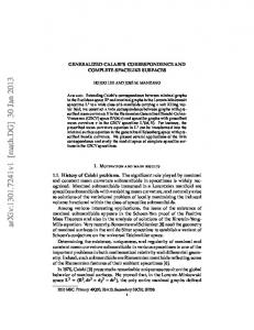
FIGURES FIG. 1. A Cartesian set of coordinates showing the directions relevant for dislocations in Al. FIG. 2. The GSF energy surfaces for displacements along a (111) plane in Al (J/m2 ) (the corners of the plane and its center correspond to identical equilibrium configurations, i.e., the ideal Al lattice): (a) from DFT pseudopotential plane-wave calculations; (b) from EAM calculations. The two energy surfaces are displayed in exactly the same perspective and on the same energy scale to facilitate comparison of important features. The EAM energy surface extends to values about 4 times larger than the maximum value displayed (black truncated regions). FIG. 3. The projections of the GSF energy surfaces onto (a) [12¯1] and (b) [101] directions from both the DFT and EAM calculations. FIG. 4. The restoring stresses along (a) [12¯1] and (b) [101] (b) directions calculated from both the DFT and EAM GSF energy surfaces. FIG. 5. The disregistry vectors in unit of the Burgers vector obtained from the DFT and EAM calculations for: (a) the screw and 60◦ dislocations; (b) the 30◦ and edge dislocations. FIG. 6. The disregistry paths for the four dislocations obtained from (a) DFT calculations; (b) EAM calculations. FIG. 7. The density distributions for the four dislocations (clockwise): screw, 30◦ , 60◦ and edge, obtained by using DFT and EAM calculations: For the 30◦ , 60◦ and edge dislocations, the characters of resultant partials within the EAM calculations are indicated (see also text). FIG. 8. The projection of the DFT GSF energy surface along [12¯1] direction with and without modifying the real energy profile. The solid curve represents the real energy profile without modification while the dashed curve represents the modified GSF energy surface but keeping the same intrinsic stacking fault energy as its real value.
24
FIG. 9. The dislocation density distribution for the edge dislocation calculated from the modified GSF energy surface (dashed line) and the real GSF energy surface without modification (solid line). The distance is in terms of the full Burgers vector. FIG. 10. The half width (in ˚ A) as a function of dislocation orientation using the two different definitions. The square stands for the definition through the disregistry vector and the dot stands for the definition through the restoring stress (only DFT results shown). FIG. 11. The core energy, elastic energy and GSF energy as a function of dislocation orientations. FIG. 12. The scaled Peierls stress as a function of the core width and the atomic spacing perpendicular to the dislocation line (the dashed line corresponds to the formula from Jo´ os et al.).
25
Fig. 1 y [111] normal to glide plane
bsin θ
O s co
θ
x
θ
glide direction
b
b
σ xy σ
zy
z dislocation line
σ
by
0.5 0.4 E 0.3 0.2 0.1 0
0.5 0.4 E 0.3 0.2 0.1 0
Fig. 3(a)
Fig. 3(b)
1.5
0.8 EAM EAM
2
GSF energy (J/m )
2
GSF energy (J/m )
0.6 1.0
0.5
0.0 0.0
DFT
0.5 1.0 Unit Burgers vector
1.5
0.4 DFT 0.2
0.0 0.0
0.2
0.4 0.6 0.8 Unit Burgers vector
1.0
Fig. 4(a)
Fig. 4(b)
0.10
0.10
Restoring stress (ev/A )
0.05
3
3
Restoring stress (ev/A )
EAM
DFT 0.00
-0.05
-0.10 0.0
0.5
1.0
Unit Burgers vector
1.5
EAM
0.05
DFT 0.00
-0.05
-0.10
0.0
0.2
0.4
0.6
Unit Burgers vector
0.8
1.0
Fig. 5 (a)
Disregistry vector (b)
1.0
o
0 DFT o 0 EAM o 60 DFT o 60 EAM
0.5
0.0 -50.0
0.0 Nodal distance (A)
50.0
Fig. 5 (b)
Disregistry vector (b)
1.0
o
30 DFT o 30 EAM o 90 DFT o 90 EAM
0.5
0.0 -50.0
0.0
Nodal distance (A)
50.0
Fig. 6 (a) 0.10
0.00
B
A
b
f (A)
-0.10
-0.20
o
0 o 30 o 60 o 90
-0.30
-0.40 0.0
0.5
1.0
a
1.5
f (A)
2.0
2.5
Fig. 6 (b) 0.2
B
A 0.0 o
0 o 30 o 60 o 90
b
f (A)
-0.2
-0.4
-0.6
-0.8 0.0
0.5
1.0
a
1.5
f (A)
2.0
2.5
Fig. 7 0.4 DFT(ρs) EAM(ρs) EAM(ρe)
30 0.3
DFT(ρe) EAM(ρe) EAM(ρs)
60
0
0.2
90
30 60
0.1
0.0 DFT(ρs) EAM(ρs)
0
DFT(ρe) EAM(ρe)
90
0.3
0.2 60
60 0.1
0.0 -10.0
-5.0
0.0
5.0
-10.0 Distance (b)
-5.0
0.0
5.0
10.0
Fig. 8 0.50 real modified
2
GSF energy (J/m )
0.40
0.30
0.20
0.10
0.00 0.0
ISF
1.0
2.0 3.0 Disregistry (A)
4.0
5.0
Fig. 9 0.40 real modified
Density
0.30
0.20
0.10
0.00 -10.0
-5.0
0.0 Unit Burgers vector
5.0
10.0
Fig. 10 3.5
half width (A)
definition 1 definition 2
3.0
2.5
2.0 0.0
30.0
60.0
Angle
90.0
Fig. 11
0.10 core energy elastic energy GSF energy
Energy (ev/A)
0.00
-0.10
-0.20
-0.30
-0.40 0.0
30.0
60.0
Angle
90.0
Fig. 12 -4.0
30
-1
-1
ln(σpab K )
-6.0
-8.0
10.9
-10.0 90
-12.0 0.0
2.0
14.9
4.0
6.0 ζ/a
8.0
10.0