Generating Domain-Specific Model Editors with Complex Editing Commands Gabriele Taentzer1 , Andr´e Crema2 , Ren´e Schmutzler2 , and Claudia Ermel2 1
Philipps-Universit¨ at Marburg, Germany
[email protected]
2 Technische Universit¨ at Berlin, Germany {crema, reneschm, lieske}@cs.tu-berlin.de
Abstract. Domain specific modeling languages are of increasing importance for the development of software and other systems. Meta tools are needed to support rapid development of domain-specific solutions. Using the Eclipse Graphical Modeling Framework (GMF), modeling languages are defined by providing a meta model using the MOF/EMF approach. Up to now, GMF provides basic editing commands only. It does not support the definition of complex editing commands which would allow e.g. to insert a complex structure into a diagram in one step. As practical tool support for the design and generation of visual editors with complex editing operations based on graph transformation, an extended version of GMF has been developed and is presented in this paper.
1
Introduction
In software system development, domain-specific visual notations are increasingly used and need a tool environment consisting of visual editors, simulators, model transformers, etc. Several Eclipse projects head for a meta technology to define domain-specific modeling languages. The Eclipse Modeling Framework (EMF) [5] can be used to define the underlying models of visual editors. Given an EMF model, a set of Java classes for manipulating the model and a basic, tree based editor for model instances are generated. The generated classes provide CRUD functionality for model elements. To realize a graphical editor, the editor code may be hand-coded on the basis of GEF, the Eclipse Graphical Editor Framework [3], which offers basic and advanced editor functionalities.As another alternative, a visual editor may be generated using the Graphical Modeling Framework (GMF) [4] which started recently as Eclipse technology subproject aiming at providing an infrastructure for generating visual editors in Eclipse. In essence, GMF forms a bridge between EMF and GEF, whereby a diagram definition is linked to a domain model which serves as input to the generation of a visual editor. GMF-generated editors offer basic editing commands to create, edit, move and delete single model elements (basic editing). Graph transformation-based editors (see e.g. Tiger [7]) show that the generation of editors with complex
editing commands is also possible. Editing e.g. control flow graphs, there might be editing commands available which insert or delete a complete decision structure in one step. In the following, we present how meta model-based editor design and generation performed by GMF, can be extended by graph transformation concepts to define and generate complex editing commands to be used in GMF-generated visual editors.
2
Examples for Complex Editing Commands
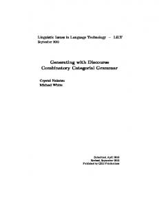
Activity diagrams are used to describe the control flow within a system, based on activities. In the following, we consider the editor generation process for a simple variant of activity diagrams consisting of start, end, decision and simple activities. The visual editor generated by pure GMF (without the extension for complex editing commands) is shown in Fig. 4 (a). It contains an example for an activity diagram with different kinds of activities mentioned above. We used the usual design process for visual editors offered by GMF. Considering the palette on the right of the generated editor, we notice that creation commands for each of the model elements are offered. Moreover, the context menus contain commands for editing and deleting model elements. Up to now, there is no way to design and generate more complex editing commands. Complex editing commands for activity diagrams can help to easily edit the diagrams in mind. For example, a well-formed activity diagram contains at least one start and one end activity. Moreover, well-formed activity diagrams contain decision branches which are explicitly merged by a decision activity, only. An example for a well-formed activity diagram is shown in Fig. 4.
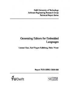
Fig. 1. Specification of complex editing commands
Fig. 1 shows the before and after patterns for sample complex editing commands. We define one editing command CreateStartGraph to generate the start diagram which consists of exactly one start and one end activity, connected by a next-relation. This command is executable in the empty editor panel only. Editing command AddSimple inserts a simple activity after another activity, where is a symbol for an abstract figure which stands for one of the following
concrete figures (start activity) or (simple activity). The name of the new activity is given by input parameter n. Please note that the source activity of next-relation 2 changes after insertion. Editing command AddDecision replaces a simple activity by a decision activity with two branches. Each branch contains one simple activity. The branches are merged afterwards by another decision activity. The AddDecision command has four input parameters: two arc inscriptions x and y, and two names n and m for the new simple activities in both branches.
3
Extending GMF by Complex Editing Commands
In this section, we discuss how GMF-based editor generation can be extended by graph transformation concepts supporting the specification of complex editor commands. 3.1
Extension of the GMF Development Environment
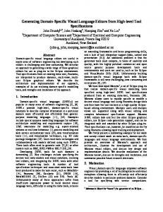
A language model is described in GMF by defining an EMF model, the so-called domain model, while the layout is specified in the graphical definition model. Now, an additional visual editor for defining complex editing commands is provided, where EMF transformation rules for complex editing commands can be defined as transformation rules based on the domain model. This step is optional. The tooling definition model is used to define the commands for the editor palette. After having defined all these models separately, the mapping model establishes a connection between them and is the input for the generation process. Fig. 2 shows an overview of the design workflow in the extended GMF using a dashboard, where the original GMF workflow is extended by the specification of a Transformation Rule Model.
Fig. 2. GMF dashboard extended by transformation rule model for editing commands
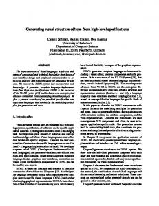
Before discussing the specification of concrete editing commands, we present the EMF model transformation approach [1] used to manipulate the underlying EMF models. The transformation concept is closely related to algebraic graph transformation. The main reason for this design decision is the basic opportunity to validate EMF model transformations on the basis of graph transformation. Basically, an EMF transformation is a rule-based modification of an EMF source model resulting in an EMF target model. Both, the EMF source and target models are typed over an EMF core model. All modifications are made in-place, i.e. the source model is not copied before modification. For efficient execution of model transformations, the rules can be translated to Java code to be integrated into generated EMF classes. Fig. 3 shows a designer for EMF transformations where the underlying meta model is depicted at the bottom and one of the transformation rules, i.e. a rule for inserting a start diagram, is shown at the top. A negative application condition ensures that this rule is applied only to the empty activity diagram. After having defined all editing commands needed analogously, all those which should show up in the palette have to be identified in the GMF tooling model, and the GMF mapping model is extended by the definition of the transformation model.
Fig. 3. Tool environment for EMF transformation
3.2
Extension of the GMF Runtime Environment
The editor generation process in the extended GMF version results in an editor as shown in Fig. 4 (b) where default editing operations as well as specifically
designed ones are provided by the palette. Please note that the editor designer selects those commands to be included in the palette.
Fig. 4. Generated editors for activity diagrams without (a) and with (b) complex editing commands
We describe the usage of the generated editor in the extended GMF version along our running example. A sequence of steps to create our sample activity diagram are shown in Fig. 5. In step 1, we start with an empty editor panel and select command CreateStartGraph from the palette. Immediately, the start activity diagram appears in the editor panel. Step 2 selects command AddSimple to add a simple activity node. This node is added after the start activity, because the negative application condition of the rule forbids to insert an activity node after a final node. Since we have only one non-final activity node, the location to apply this command is unique in the current situation. In Step 3, we select command AddSimple again, but this time it can be applied at two locations: the new activity node can be inserted either after the start activity, again, or after the new simple activity node named “First”. Thus, instead of applying the rule, the editor now highlights the two possible locations. In step 4, one of the highlighted nodes is selected per mouse click, and the command is applied accordingly. Step 5 combines two atomic steps: command InsDecision is selected, and the activity nodes “First” and “Second” are clicked on to specify between which two activity nodes the complete decision structure is to be inserted. Afterwards, in step 5, command DeleteSimple is selected in the palette. This leads to two activity nodes being highlighted, which may be deleted by the rule.
Fig. 5. Editing steps using complex editing operations in extended GMF
4
Conclusion
In this paper, we presented an approach generating visual editors by GMF extended by complex editing commands. Thus, using pure GMF, a visual editor can be generated which offers basic editor commands for each model element only. For the generation of complex editor commands an additional model is needed. We use EMF transformation rules to formulate commands based on the given domain model. To the best of our knowledge, no other meta CASE tool based on meta models offers the possibility to define complex editing commands. Besides pure editing commands, also model optimizations such as model refactorings, may be realized with the proposed approach. Moreover, simulation of behaviour models can be defined by this approach. Thus, this work can be considered as a starting point for the generation of powerful and flexible domainspecific visual editors in Eclipse.
References 1. Biermann, E., Ehrig, K., K¨ ohler, C., Kuhns, G., Taentzer, G., Weiss, E.: Graphical Definition of In-Place Transformations in the Eclipse Modeling Framework. In: Model Driven Engineering Languages and Systems, 9th International Conference, MoDELS 2006. LNCS, Springer, 2006. http://tfs.cs.tu-berlin.de/emftrans 2. Eclipse Consortium, Eclipse, 2006, available at http://www.eclipse.org. 3. Eclipse Consortium, Eclipse Graphical Editing Framework (GEF), 2006, available at http://www.eclipse.org/gef. 4. Eclipse Consortium, Eclipse Graphical Modeling Framework (GMF), 2006, available at http://www.eclipse.org/gmf. 5. Eclipse Consortium, Eclipse Modeling Framework (EMF), 2006, available at http: //www.eclipse.org/emf. 6. Ehrig, K. and Ermel, C. and H¨ ansgen, S. and Taentzer, G., Generation of Visual Editors as Eclipse-Plugins. Automated Software Engineering’05, IEEE Computer Society, 2005, http://tfs.cs.tu-berlin.de/~tigerprj.