Geometrical Modeling Using Multiregional Marching Tetrahedra for ... experimental animal is required; to perform finite element-based reconstruction computation, the ... animal, which are the optical signatures of cells/genes generated by expression of reporter genes encoding .... K is a 4x4 fundamental error quadric matric:.
Geometrical Modeling Using Multiregional Marching Tetrahedra for Bioluminescence Tomography a
Alexander Cong, bYi Liu, aD. Kumar, aWenxiang Cong and a,bGe Wang a
Bioluminescence Tomography Laboratory b CT/Micro-CT Laboratory Department of Radiology, University of Iowa, 200 Hawkins Drive, Iowa City, IA 52242, USA
ABSTRACT Localization and quantification of the light sources generated by the expression of bioluminescent reporter genes is an important task in bioluminescent imaging of small animals, especially the generically engineered mice. To employ the Monte Carlo method for the light-source identification, the surfaces that define the anatomic structures of the small experimental animal is required; to perform finite element-based reconstruction computation, the volumetric mesh is a must. In this work, we proposed a Multiregional Marching Tetrahedra (MMT) method for extracting the surface and volumetric meshes from segmented CT/micro-CT (or MRI) image volume of a small experimental animal. The novel MMT method extracts triangular surface mesh and constructs tetrahedra / prisms volumetric finite element mesh for all anatomic components, including heart, liver, lung, bones etc., within one sweep over all the segmented CT slices. In comparison with the well-established Marching Tetrahedra (MT) algorithm, our MMT method takes into consideration of two more surface extraction cases within each tetrahedron, and guarantees seamless connection between anatomical components. The surface mesh is then smoothed and simplified, without losing the seamless connections. The MMT method is further enhanced to generate volumetric finite-element mesh to fill the space of each anatomical component. The mesh can then be used for finite element-based inverse computation to identify the light sources. Keywords: Bioluminescence imaging, surface mesh, volumetric mesh, multiregional marching tetrahedra, mesh simplification.
1. INTRODUCTION Bioluminescent imaging becomes increasingly popular because of its high sensitivity and molecular level imaging ability. The most critical task for bioluminescent imaging is to localize and quantify light sources in an experimental animal, which are the optical signatures of cells/genes generated by expression of reporter genes encoding bioluminescent proteins. In experiment, we measure the light emission from the skin of a small animal, and then perform inverse computation/reconstruction to identify the internal light sources. We are employing two numerical schemes for this task; they are based on the Monte Carlo and finite element methods1, respectively. For these methods, information for the anatomical structures of the animal must be provided. Specifically, Monte Carlo simulation requests 3D surfaces that define the anatomical components, the finite-element reconstruction is based on volumetric mesh. Thus a method to construct surface/volumetric mesh from CT/micro-CT images of the experimental animal is essential for our bioluminescent imaging study. For surface mesh generation, the well-known Marching Cubes (MC) algorithm2 was proposed in 1987 to extract isosurface from CT/MR image volume. The algorithm visits each cube cell formed by eight adjacent voxels in the image volume, and performs local triangulation by interpolating new vertices along the cell edges. It was later noticed that this MC algorithm suffers from ambiguity problem3, that is “holes” may be caused on the surface it constructs, which is unfavorable for Monte Carlo and finite element simulations. An alternative Marching Tetrahedra (MT)4 algorithm was proposed to avoid the ambiguity. It first decomposes a cube into five tetrahedra, and then performs triangulation in each tetrahedron. Since there are only three possible cases for triangulation within a tetrahedron, the MT algorithm is much more straightforward than the MC algorithm, and can eliminates the ambiguity problem. The above-mentioned isosurface-extraction algorithms only extract surfaces of one single material phase with each sweep over the CT/MR image volume. Wu and Sullivan have recently proposed a multiple-material marching cubes algorithm (M3C)5 that extracts all the surfaces that define different material regions with one sweep over the segmented
756
Medical Imaging 2005: Visualization, Image-Guided Procedures, and Display, edited by Robert L. Galloway, Jr., Kevin R. Cleary, Proc. of SPIE Vol. 5744 (SPIE, Bellingham, WA, 2005) · 1605-7422/05/$15 · doi: 10.1117/12.595403
CT/MR image volume. In this work, we propose a Multiregional Marching Tetrahedra (MMT) algorithm to extract all the surfaces of different anatomical components from segmented CT/micro-CT images within a single pass. The extracted surfaces are then smoothed and simplified for the purpose of Monte Carlo-based bioluminescent light-sources reconstruction. Simplification of the surface mesh makes use of the pair decimation method with quadric error metrics (Garland and Heckbert6). This method can effectively simplify the surface mesh, while maintaining good geometric fidelity and connectivity. Before and after the mesh simplification, we improve the mesh quality with a simple Lapacian smoothing method13. Optimization-based techniques should deliver better smoothing results, with higher computational expense.7 To generate volumetric mesh for finite element analysis, octree-based method8, advancing front technique9 and Delaunay technique10 are used frequently. The Marching Cube algorithm has been extended to perform tetrahedralization between two isosurfaces directly from volume data.11 Nielson and Sung extended the Marching Tetrahedra method for to extracting tetrahedral mesh between interval volumes.12 Here, we extend our MMT method to construct multiplematerial volumetric mesh directly from segmented CT images. A sample finite-element mesh of a mice trunk is reconstructed and presented.
2. MULTIREGIONAL MARCHING TETRAHEDRA ALGORITHM Our Multiregional Marching Tetrahedra (MMT) method is detailed in this section. 2.1. Image Segmentation Before performing MMT surface extraction, the CT/micro-CT images of the experiment animal are assumed segmented, such that all the voxels in a segmented region (corresponding to a anatomical component) have identical greyscale value. Segmentation is critical for the correctness and fidelity of the model, but is beyond the scope of this work. 2.2. Tetrahedral Decomposition The MMT algorithm reads two adjacent segmented CT slices, and forms large number of cubes that fill the space between these two slices. Each cube is made of four voxels from the upper CT slice, and correspondingly four voxels from the lower slice.2 Each cube is then decomposed into five tetrahedra. There are two patterns for decomposition, according to the location of the cube. As shown in Fig. 2.1, for each cube, we choose the far-left vertex on the upper surface as the representative vertex. It is noted that the choice is arbitrary, but should be kept consistent for all the cubes considered in the MMT surface extraction. Denoting the voxel coordinates for the representative vertex as (nx, ny, nz), the number N=nx+ny+nz determines the decomposition pattern: cubes with even N are decomposed as in Fig. 2.1 (a), those with odd N are decomposed as in Fig. 2.1 (b). While marching through each of the cubes, this decomposition method prevents face and edge mismatch of the neighboring cubes, therefore easily eliminate the ambiguity problem with the Marching Cube algorithm.4 (nx,ny,nz)
(a) Fig. 2.1.
(nx,ny,nz)
(b) Tetrahedra decomposition of a cube. (a) is an even cube decomposition, (b) is an odd cube decomposition.
2.3. Surface Generation Now we consider each tetrahedron individually. Each vertex of a tetrahedron is associated with a greyscale value that determines which region the vertex belongs to (remind that each anatomical component is assigned with one greyscale in
Proc. of SPIE Vol. 5744
757
the segmented CT images). If all the four vertices have the same greyscale value, the whole tetrahedron belongs to one anatomical component, and thus no surface is extracted within. Otherwise, we insert new vertices at the midpoints of some edges, and form in the tetrahedron patch(es) for the surface(s) that define the anatomical components. By sweeping over all the tetrahedra, seamless surfaces that define all the anatomical components will be extracted, without any “hole” or ambiguity. Specifically, there are four possible configurations for surface extraction within a tetrahedron, as shown in Fig. 2.2. v1
v1 r1
m1
m3
m1
m2
m2 r2
v2
v2
r1
m3
m2 r3
v2
m1
r1 m2
v4 m5
m4
v3 (b)
v1
v1
r2
v4
m4 m3
v3 (a)
m1
r1
r2
v4
r2 v2
m6 r3
m3 r4 v4 m5
m4 v3 v3 (c) (d) Fig. 2.2. 4 cases of surface intersection with a tetrahedron (a) and (b) are the cases that a tetrahedron has vertices in 2 regions (b) is the case that a tetrahedron has vertices in 3 regions, and (d) is a tetrahedron has vertices spread in 4 regions.
2.3.1. Case I and II For the first two cases, a tetrahedron is shared by two adjacent material regions, say r1 and r2. Case I (Fig. 2.2 (a)) represents the configuration that one vertex v1 (orange in color) of the tetrahedron belong to one material region r1 while the other three, v2 v3 and v4 (yellow), are in another adjacent material region r2. For this case, a triangle patch is formed with three vertices m1, m2, m3 (blue) on the edges v1�v2, v1�v3 and v1�v4, respectively. The triangle (m1 m2 m3) is part of the surface share by r1 and r2. The second case is similar, but with two vertices v1 and v3 in region r1, and the other two v2 and v4 in region r2. New vertices m1, m2, m3 and m4 are inserted at the midpoints of the edges, as in Fig. 2.2 (b), and form two triangles: (m1 m2 m3 ) and (m3 m4 m2), which separate the regions r1 and r2.
2.3.2. Case III Case III involves three different material regions, r1, r2 and r3 ( Fig. 2.2 (c)), with vertex v1 in r1, v2 and v4 in r2 and v3 in r3. For this case, we insert five midpoints, m1, m2, m3 m4 and m5, along the edges, and form three triangle patches: (m1 m2 m3) separates r1 from the others, (m1 m4 m3) and (m3 m4 m5) divide r2 and r3.
758
Proc. of SPIE Vol. 5744
2.3.3. Case IV In the last case (Fig. 2.2 (d)), the four vertices belong to four different material regions, r1, r2, r3 and r4, respectively. Six new vertices are inserted along all edges of the tetrahedron, and form three triangle boundary patches that split the tetrahedron and assign the parts to the four different regions. Specifically, the part above triangle (m1 m2 m3) belongs to r1 , that left to triangle (m1 m4 m6) belongs to r2 , that right to triangle (m3 m5 m6) belongs to r4 , and the rest belongs to r3. These four cases handle all possibilities of triangulation within a tetrahedron at the boundary between multiple regions, therefore enable the generation of boundary surfaces of all regions of a CT data volume within a single pass of marching tetrahedral.
3. MESH QUALITY IMPROVEMENT This section describes the process of mesh quality improvement by mesh smoothing and simplification. 3.1. Laplacian Smoothing The surface mesh extracted by MMT may have stepped aliasing. The aliasing must be mitigated to obtain a more realistic appearance of the surface model. Here we apply the simple Laplacian smoothing technique to each individual vertex.13 That is, each vertex position is adjusted according to the position of its neighboring vertices. This simple idea is illustrated in Fig. 3.1 and follows formula: vnew = v + λ
∑ (v − v ) , N
i
i =1
where v denotes the original coordinate of the vertex, and vnew its new coordinate after smoothing. The summation is taken over the coordinate vi of all the N neighboring vertices, as shown with Fig. 3.1. The quantity λ ( ∈[0,1] ) is a user-defined weight function. vN v v1
v2
vnew
vi Fig. 3.1 Laplacian smoothing operation to an individual vertex As this smoothing method only moves the vertices position, the topology of the surface model will not change. 3.2. Surface Simplification To reduce the density of the surface mesh, we adopted the edge decimation method with quadric error metric, as proposed by Garland6. The method reduce This method first assigns an error metric to each vertex. The quadric error metric used is as the following:
∆(v ) =
∑ (v p)( p v) = ∑ v ( pp )v = v ∑ K T
T
p ∈P ( v )
T
p∈P ( v )
T
T
p∈P ( v )
p
v
where K p is a 4x4 fundamental error quadric matric:
Proc. of SPIE Vol. 5744
759
2
K p = pp
T
=
a ab ac ad
ab b
2
ac bc 2
bc
c
bd
cd
ad bd . cd 2 d
6
Details of the formulas are referred to Garland and Heckbert . For all valid pairs compute the optimal target vertex position. The error metric of the target vertex is the sum of the two vertices’ error metrics on the edge that have been decimated. With the new vertex position and error metric, the error at the new vertex can be computed, which is the cost of contracting this pair. The pairs will be put on a heap, keyed by cost of the pair. After the pair heap is constructed, interactively remove the lowest cost pair to perform pair contraction. Therefore, always the pair with lowest cost is decimated, which make the least change to the original shape. The pair decimation procedure is as in Fig. 3.2. edge to be contracted
vj
vi
Fig. 3.2
contract
vnew
Pair contraction of edge vi vj.
We modify the simplification algorithm slightly to ensure that if an edge of one material boundary mesh got decimated, the same edge in the adjacent material boundary mesh also get decimated in the same way, so the connectivity of the surface model won’t change.
4. VOLUME MESH GENERATION In this section, we extend the MMT algorithm from surface mesh generation to volumetric mesh generation. All the procedures of MMT algorithm remain the same, except that we change the four configurations (Fig. 2.2(a~d)) for surface extraction to four decomposition patterns of a boundary tetrahedron. First, for case that a tetrahedron belongs to a single region, we simply add the tetrahedron to the finite-element mesh set of the region. For tetrahedra on the interface(s) between two or more neighboring material regions, we will split the tetrahedra, and assign the parts to different regions. The following four cases give details on how to decompose a boundary tetrahedron into smaller tetrahedron and prisms, and how to distribute the parts. 4.1. Case I and II v1
v1
r1 r1 r2
v4
v4
v2
r2
v2 v3 (a)
(b) Fig 4.1 Decomposition of boundary tetrahedra (a) Case I (b) Case II
760
Proc. of SPIE Vol. 5744
v3
Cases I and II are shown with Fig 4.1, where a tetrahedron is shared by two neighboring material regions Similar to Fig. 2.2 (a) for surface extraction Cases I, we first insert three new vertices, and form a triangle patch that split the tetrahedron, as in Fig. 4.1 (a). The smaller tetrahedron is added to the set of finite element mesh for region r1, while the prism belongs to region r2. Case II corresponds to Fig 2.2 (b), where two vertices v1 and v3 in region r1, and the other two v2 and v4 in region r2. We split the tetrahedron into two prisms, as in Fig. 4.1 (b), and assign one prism to region r1 and the other one to region r2.
4.2. Case III v1
r1
v4
r2 r3
v2
v3 Fig. 4.2 Decomposition of a boundary tetrahedron Here in Case III, we have a tetrahedron on the boundary of three regions. Two of its vertices (v3 and v4) are in region r3, one (v1) in region r1 and the other one (v2) in region r2. The tetrahedron can therefore be decomposed into three parts as shown in Fig. 4.2, one part for each region. We first split the tetrahedron into two prisms as for case II. The prism with two vertices (v3 and v4) of the tetrahedron is given to r3, the other prism is further decomposed into a smaller tetrahedron and a smaller prism, which are then assigned to region r1 and r2, respectively. v1 v1
m1
m3
r2
m3 m1
m2
v2
v4
m6
m1
m2 m2
m5 m4 v3 (a)
m3
m6 (b)
Fig. 4.3 Decomposition of a boundary tetrahedron (a) A tetrahedron whose 4 vertices are in 4 different regions. (b) Decomposition of 1/4 of the tetrahedron into two smaller tetrahedra 4.3. Case IV Here we consider the case that four vertices of a boundary tetrahedron are spread into four different regions. In this case, we first insert six new vertices as we did in Fig. 2.2 (d), and split the tetrahedron evenly into four identical parts; each of
Proc. of SPIE Vol. 5744
761
which contains two smaller tetrahedra. Fig. 4.3(b) shows such two smaller tetrahedra triangle (m1 m2 m3 v1) and (m1 m2 m3 m6) for the upper part. Then each part is simply assigned to a region as its finite element mesh. For our purpose of computation, mixed type of finite element mesh is allowed. Prisms can be further decomposed into three tetrahedra if pure tetrahedral mesh is desired. This tetrahedralization procedure produces no ill finite element. All adjacent anatomical components that have been tetrahedralized are seamless connected to each other. The volume mesh can be generated simultaneously with surface mesh within a single pass of marching tetrahedra.
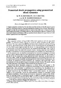
(a) Fig. 5.1
(b) (a) Micro-CT slice of a mouse phantom of chest area (c) 3D volumetric mesh of the phantom
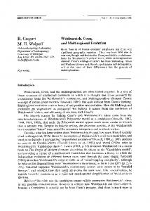
5. RESULTS Here we present our results for meshes generated from segmented Micro-CT image volume. We first consider a physics phantom, which is cylindrical in shape with cross-section shown in Fig. 5.1. CT scanning is first conducted, and then the slices are segmented. Our MMT procedure is then performed to contract volumetric finite-element mesh for the phantom, directly from segmented CT data. The result is shown with Fig. 5.1(b). We further exam our MMT method with segmented CT slices of a living mice (see Fig. 5.2(a) for a sample slice). The trunk of the mice is reconstructed as finite element mesh (Fig. 5.2.(b)), with anatomical components including heart, liver, lung and bones.
6. CONCLUSION The main contribution of this work is to propose a Multiregional Marching Tetrahedra method for generating surface and volumetric mesh model of small animal that allows all the anatomical components to be connected seamlessly. The model we build by the MMT method is suitable as input for our light-source reconstruction computation. Specifically, the surface mesh model, which describes the boundary of each anatomical component, is for the Monte Carlo method. With the mesh simplification, we can deliver surface models with different levels of detail to reduce the computational cost. The finite element volumetric model is for our finite element-based diffusion method. The seamless connection between different regions ensures the correctness of computation based on our model.
762
Proc. of SPIE Vol. 5744
(a) Fig. 5.2
(b) (a) Segmented micro-CT slice of mouse (b) Rendering of a volumetric mesh of a segmented mouse containing heart, liver, lung and bones
REFERENCES 1. 2. 3. 4. 5. 6. 7. 8. 9. 10. 11. 12. 13.
W.Cong, et al, “A practical method to determine the light source distribution in bioluminescent imaging,” in Developments in X-Ray Tomography IV, edited by Ulrich Bonse, Proceedings of SPIE Vol.5535 pp. 679-686 W.E.Lorenson and H.E.Cline, “Marching cubes: A high resolution 3D surface construction algorithm,” Proc. ACM Siggraph, Vol. 21-4, pp. 163-169, Anaheim, Calif., July 1987 G.Nielson and B.Hamann, “The asymptotic decider: Resolving the ambiguity in marching cubes,” Proc. Conf. Visualization, pp.83-91,1991 A. Gueziec and R. Hummel, “Exploiting Triangulated Surface Extraction Using Tetrahedral Decomposition,” IEEE Transactions on Visualization and Computer Graphics Vol. 1, No. 4, pp.328-342, 1995 Z.Wu and J.M.Sullivan, “Multiple material marching cubes algorithm,” International Journal for Numerical Methods in Engineering, John Wiley & Sons, Ltd., Vol 58, No. 2, pp.189-207, July 2003 M. Garland and P. S. Heckbert, “Surface Simplification Using Quadric Error Metric,” SIGGRAPH 97 L. A. Freitag, “On combining Laplacian and optimization-based smoothing techniques,” Trends in Unstructured Mesh Generation, ASME Applied Mechanics Division, AMD-Vol 20, pp.37-44, 1997 M.S.Shephard and M.K.Georges, “Three-dimensional mesh generation by finite octree technique,” 6th Internathional Meshing Roundtable, pp. 195-196, 1997 R.Lohner and P.Parikh, “Three dimensional grid generation by the advancing –front method,” International Journal for Numerical Methods in Fluids, Vol 8, pp.1136-1149, 1988 J.R.Shewchuk, “Tetrahedral Mesh Generation by Delaunay Refinement,” Symposium on Computational Geometry, pp. 86-95, 1998 I.Fujishiro, Y.Maeda, H.Sato, and Y.Takeshima, “Volumetric data exploration using interval volume,” IEEE Transactions on Visualization and Computer Graphics, Vol. 2(2) pp. 144-155, 1996 G.M.Nielson and J.Sung, “Interval volume tetrahedrization,” IEEE Visualization, pp. 221-228, 1997 Schroeder W., Martin K., Lorensen B., "The Visualization Toolkit, An Object-Oriented Approach to 3D Graphics", 2nd edition, pp. 388, Prentice Hall, 1997
Proc. of SPIE Vol. 5744
763