sensors Article
Global Navigation Satellite System Multipath Mitigation Using a Wave-Absorbing Shield Haiyan Yang 1,2,3, *, Xuhai Yang 1,3 , Baoqi Sun 1,3 and Hang Su 1,2,3 1 2 3
*
National Time Service Center, Chinese Academy of Sciences, Xi’an 710600, China;
[email protected] (X.Y.);
[email protected] (B.S.);
[email protected] (H.S.) University of Chinese Academy of Sciences, Beijing 100049, China Key Laboratory of Precision Navigation and Timing Technology, National Time Service Center, Chinese Academy of Sciences, Xi’an 710600, China Correspondence:
[email protected]; Tel.: +86-29-8389-0540; Fax: +86-29-8389-0326
Received: 3 July 2016; Accepted: 16 August 2016; Published: 22 August 2016
Abstract: Code multipath is an unmanaged error source in precise global navigation satellite system (GNSS) observation processing that limits GNSS positioning accuracy. A new technique for mitigating multipath by installing a wave-absorbing shield is presented in this paper. The wave-absorbing shield was designed according to a GNSS requirement of received signals and collected measurements to achieve good performance. The wave-absorbing shield was installed at the KUN1 and SHA1 sites of the international GNSS Monitoring and Assessment System (iGMAS). Code and carrier phase measurements of three constellations were collected on the dates of the respective installations plus and minus one week. Experiments were performed in which the multipath of the measurements obtained at different elevations was mitigated to different extents after applying the wave-absorbing shield. The results of an analysis and comparison show that the multipath was mitigated by approximately 17%–36% on all available frequencies of BeiDou Navigation Satellite System (BDS), Global Positioning System (GPS), and Global Navigation Satellite System (GLONASS) satellites. The three-dimensional accuracies of BDS, GPS, and GLONASS single-point positioning (SPP) were, respectively, improved by 1.07, 0.63 and 0.49 m for the KUN1 site, and by 0.72, 0.79 and 0.73 m for the SHA1 site. Results indicate that the multipath of the original observations was mitigated by using the wave-absorbing shield. Keywords: global navigation satellite system (GNSS); wave-absorbing shield; multipath; single-point positioning (SPP)
1. Introduction Multipath effects are a key parameter in global navigation satellite system (GNSS) observation quality. These effects have different impacts on different frequencies. It is difficult to eliminate these impacts by differential technology or establishing a mathematical model [1–6]. Multipath effects are a major error source that jeopardizes GNSS positioning accuracy. The effects influence the accuracy of single-point positioning (SPP); moreover, severe multipath effects slow the convergence of precision point positioning (PPP) [7,8]. Therefore, mitigating the multipath influence is critical for improving GNSS positioning accuracy. Many methods relating to GNSS multipath and its mitigation have been proposed and developed. These methods can be respectively classified as antenna, signal, and measurement processing [7–15]. Improvement of antenna design mainly focuses on the lower gain at low satellite elevations, such as choke-ring antennas and ground planes. To model multipath variation, the measurement processing involved in the above studies leverages the relationship between the multipath and elevation, and between the multipath and signal-to-noise ratio (SNR) measurements. Other methods, such as Sensors 2016, 16, 1332; doi:10.3390/s16081332
www.mdpi.com/journal/sensors
Sensors 2016, 16, 1332 Sensors 2016, 16, 1332
2 of 13 2 of 12
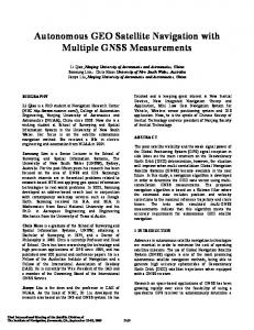
Other such as wavelet and been sidereal have beenmultipath used to waveletmethods, decomposition and siderealdecomposition filtering, have also usedfiltering, to denoise and also mitigate denoise and mitigate multipath effects [10,11]. effects [10,11]. The aboveresearch researchhashas focused on hardware and measurements post-processing The above focused on hardware designdesign and measurements post-processing methods. methods. However, it should be noted that careful site selection and improved observation However, it should be noted that careful site selection and improved observation conditions are the conditions areforthe best remedies for therefore multipath effects. We therefore propose installation a best remedies multipath effects. We propose installation of a wave-absorbing shield of with wave-absorbing shield with a diameter of 1.2 m around the antennas of GNSS sites to improve the a diameter of 1.2 m around the antennas of GNSS sites to improve the local observation conditions and local conditions and thereAbsorbing by mitigate the multipath material is there observation by mitigate the multipath effects. material is typicallyeffects. appliedAbsorbing to the antenna itself to typically applied to while the antenna itself to on mitigate multipath, while some antennas the market mitigate multipath, some antennas the market include absorbing material toonattenuate the include absorbing material to attenuate the surface waves [12,14,15]. surface waves [12,14,15]. This This paper paper is is organized organized as as follows: follows: the the structure structure and and main main design design parameters parameters of of the the proposed proposed wave-absorbing shield are first introduced in greater detail. In Sections 3 and 4, we describe wave-absorbing shield are first introduced in greater detail. In Sections 3 and 4, we describe the the multipath multipath combination combination of of code code and and carrier carrier phase phase observables, observables, as as well well as as the the multiple multiple perspective perspective analysis thatwas wasconducted conducted on time the series time series of multipath observations BeiDou Satellite analysis that on the of multipath observations of BeiDouof Satellite Navigation Navigation System (BDS), Global Positioning System (GPS), and Global Navigation Satellite System System (BDS), Global Positioning System (GPS), and Global Navigation Satellite System (GLONASS) (GLONASS) satellites over the period of two weeks. To verify the proposed method, SPP satellites over the period of two weeks. To verify the proposed method, SPP was conducted. was The conducted. The positioning results before and after multipath mitigation are compared in Section positioning results before and after multipath mitigation are compared in Section 5. In Section 5. 6, In 6, our are conclusions are presented. ourSection conclusions presented. 2. 2. Wave-Absorbing Wave-AbsorbingShield Shield The The proposed proposed shield is primarily composed of a wave-absorbing isolation isolation plate plate and and wave-absorbing wave-absorbing materials. materials. As As shown shown in in Figure Figure 1, 1, aa 11 mm mm thick aluminum wave-absorbing wave-absorbing isolation isolation plate plate is is attached attached to to aa 1.2 m diameter parabolic metal plate with a 5° 5◦ angle angle between between the the edge edge of of the the parabolic metal plate and the phase center of the GNSS antenna. The surface of the wave-absorbing parabolic metal plate and the The surface of wave-absorbing isolation isolation plate plate is is covered covered with with wave-absorbing wave-absorbing material. material. InInthe the design design of of wave-absorbing wave-absorbing shield, shield, performance of multipath mitigation must be considered without effecting GNSS observations performance of multipath mitigation must be considered without effecting observations collected. angle was set set as 5° to the angle,angle, whichwhich is typically set as collected. The Theinstallation installation angle was asaccording 5◦ according tocutoff the cutoff is typically about GNSS data collecting and processing, and guarantees the integrity collected set as 5°–15° about during 5◦ –15◦ during GNSS data collecting and processing, and guarantees the of integrity of observations. The diameter of the wave-absorbing shield is the result of many factors, such as collected observations. The diameter of the wave-absorbing shield is the result of many factors, such mitigation performance, performance andand price rate, easy to install, and so so on.on. as mitigation performance, performance price rate, easy to install, and
(a)
(b)
Figure ofof thethe wave-absorbing shield (in (in Figure 1a, 1a, green represents the Figure 1. 1. Structure Structure(a) (a)and andphoto photo(b) (b) wave-absorbing shield Figure green represents wave-absorbing material, blue represents the wave-absorbing isolation plate, gray represents the the wave-absorbing material, blue represents the wave-absorbing isolation plate, gray represents the support the choke-ring choke-ring antenna). antenna). support structure, structure, the the circular circular shape shape represents represents the
Direct and reflected signals with an elevation angle of less than 5°◦ (for the zenith distance of Direct and reflected signals with an elevation angle of less than 5 (for the zenith distance of larger than 85°) are isolated by the wave-absorbing isolation plate, which requires excellent larger than 85◦ ) are isolated by the wave-absorbing isolation plate, which requires excellent isolation isolation performance. Isolation performance refers to the total attenuation value of the radial performance. Isolation performance refers to the total attenuation value of the radial electromagnetic electromagnetic radiation energy after passing through a barrier. This value is expressed in dB. The formula for calculating the isolation performance is [16,17]:
Sensors 2016, 16, 1332
3 of 13
radiation energy after passing through a barrier. This value is expressed in dB. The formula for calculating the isolation performance is [16,17]: SE = R + A + K
(1)
where SE is the isolation performance, R is the reflection loss on both sides of the wave-absorbing isolation plate, and A is the absorption loss of the isolation plate. In addition, K is the internal wave emission correction factor of the isolation plate. Among these parameters, A is the most important for the isolation performance; when A > 10 dB, the R and K values are usually ignored. According to Schelkunoff's theory of electromagnetic shielding and shielding efficiency [17,18], the formula for p A is A = 1.314t f σx µ x , where, t denotes the thickness (cm) of the isolation plate, f is the frequency (Hz), σx is the relative conductivity of the absorbing isolation plate material, and µ x is the relative permeability of the wave-absorbing isolation plate material. Table 1 outlines the test results for the isolation performance of a 1 mm thick aluminum wave-absorbing isolation plate on different frequencies. According to Equation (1), the isolation performance of the wave-absorbing shield is more than 120 dB in 1~3 GHz frequency range, which is excellent. Therefore, the wave-absorbing shield can efficiently shield disturb signals from low elevation. Table 1. Performance of the wave-absorbing isolation plate. Frequency (Hz)
σx
µx
A (dB)
SE (dB)
1.0 × 10⁹ 1.5 × 10⁹ 2.0 × 10⁹ 2.5 × 10⁹ 3.0 × 10⁹
0.17 0.17 0.17 0.17 0.17
1 1 1 1 1
1713.6 2098.8 2423.5 2708.9 2968.1
>120 >120 >120 >120 >120
Wave-absorbing materials mainly absorb signals that are reflected by the wave-absorbing isolation plate and direct signals from satellites and other objects. Ten-centimeter-thick cone rubber absorbing materials were used in this application out of the consideration for the environmental adaptability. Test results show that the absorption performance for vertical incident waves is superior to 15 dB in the 1~3 GHz frequency range. The used materials match the electromagnetic wave frequency characteristics of the GNSS satellites’ transmission signals. Therefore, GNSS signals are largely transmitted from the surface to the interior of the material, which reduces signal reflection and absorbs or attenuates the internal incident disturb signals [19,20]. Compared with the methods in literature [12], the advantages of our methodology are as follows. Firstly, the shape of the device adopts a ground plane instead of circular paraboloid. Secondly, using rubber-absorbing materials rather than foam ensures normal work outside. Thirdly, the present method synthetically utilizes the circular paraboloid and rubber absorbing materials together, and not isolation. 3. Measurement Collection and Validity The experiments were performed at the international GNSS Monitoring and Assessment System (iGMAS) [21] sites: SHA1 (Shanghai, China, 31◦ 5.980 N, 121◦ 12.030 E) and KUN1 (Kunming, China, 25◦ 1.800 N, 102◦ 47.470 E). The sites were equipped with Unicore UB4B0I multi-frequency multi-GNSS receivers and NOV750 choke-ring antennas. The antennas were mounted on the top of a concrete pillar and were located higher than other adjacent buildings. However, the tall trees, which were planted at a distance of at least 30 m from the antennas, were a main source of reflected signals (see Figure 2). Based on the test, the multipath effect at the two sites was relatively low. The wave-absorbing shields were installed on 28 April 2016 and 8 May 2016, at the respective SHA1 and KUN1 sites. Figure 2 shows the installed wave-absorbing shield and the Unicore multi-GNSS multi-frequency receivers and antennas that were used in the experiment. According to the design
Sensors 2016, 16, 1332
4 of 12
to the design requirements, signals below the satellite elevation of 5° will be lost owing to obscuration by the wave-absorbing shield. Sensors 2016, 16, 1332
4 of 13
Measurements for the present study were collected from the two sites on the triple-frequency GPS (L1, L2, L5) and BDS (B1, B2, B3), as well as the dual-frequency GLONASS (G1, G2). The requirements, below the elevation of 5◦ will wave-absorbing be lost owing to obscuration by the measurementssignals were collected onsatellite the dates of the respective shield installations wave-absorbing shield. plus and minus one week at a sampling interval of 30 s.
(a)
(b)
(c)
(d)
Figure 2. SHA1 site: without (a) and with (b) the wave-absorbing shield; KUN1 site: without (c) and with (d) the wave-absorbing shield.
Figure 3 shows the sky plots of BDS, GPS, and GLONASS at the KUN1 and SHA1 sites after the wave-absorbing shield installation. The cutoff elevation was set as 5°. From these figures, we can see the elevation and azimuth at KUN1 and SHA1 (a) (b)of each satellite observed (c) (d) site. The signals in all directions be site: consecutively tracked above 5° elevation. should beandnoted that the Figurecan 2. SHA1 without (a) and with (b) the wave-absorbing shield; KUN1Itsite: without (c) Figure 2. SHA1 site: without (a) and with (b) the wave-absorbing shield; KUN1 site: without (c) and wave-absorbing shield has no influence on the measurements collected. In addition, the tracking with (d) the wave-absorbing shield. with (d) the wave-absorbing shield. signals of the GPS, GLONASS, and BDS (C11–C14) medium earth orbit (MEO) satellites are lost Figure 3 shows the sky plots of BDS, GPS, and GLONASS at the KUN1 and SHA1 sites after when they move below anpresent elevation 5°.collected BDS geostationary orbitthe (GEO) satellites (C01–C05) forshield the study of were from the triple-frequency theMeasurements wave-absorbing installation. The cutoff elevation wastwo set sites as 5°.onFrom these figures, weGPS always remain over the equator. BDS inclined geosynchronous orbit (IGSO) satellites (L1, BDS (B1, B2, B3), as well as the dual-frequency G2). The measurements canL2, seeL5) theand elevation and azimuth of each satellite observed atGLONASS KUN1 and(G1, SHA1 site. The signals in (C06–C10) havewere aallground track ofbe figure-eight loops with a mean longitude. A data gap exists on account of collected oncan the dates of the respective wave-absorbing shield installations and minus directions consecutively tracked above 5° elevation. It should beplus noted that theone week at elevation a sampling interval s. wave-absorbing shield has of no30influence on the measurements collected. In addition, the tracking the satellite measuring below 5°. signals of the GPS, GLONASS, and BDS (C11–C14) medium earth orbit (MEO) satellites are lost when they move below an elevation of 5°. BDS geostationary orbit (GEO) satellites (C01–C05) always remain over the equator. BDS inclined geosynchronous orbit (IGSO) satellites (C06–C10) have a ground track of figure-eight loops with a mean longitude. A data gap exists on account of the satellite elevation measuring below 5°.
(a)
(b)
(a)
(d)
(b)
(e)
(c)
(c)
(f)
(d) Figure 3. Sky plot ofofthree constellations after the wave-absorbing shield(f)installation atsite the KUN1 Figure 3. Sky plot three constellations after the(e) wave-absorbing shield installation at the KUN1 on 11 May 2016, and SHA1 site (down) on 4 May 2016. KUN1: BDS (a); GPS (b) and GLONASS (c); site onFigure 11 May 2016, SHA1 site (down) onthe 4 May 2016. KUN1: (a); GPS (b)KUN1 and GLONASS 3. Sky plotand of three constellations after wave-absorbing shieldBDS installation at the SHA1: BDS (d); and GLONASS (f). on The elevation is BDS 5◦ . (a); site on 11 May 2016, and SHA1 site (down) 4 cutoff May KUN1: (c); SHA1: BDS (d);GPS GPS(e) (e) and GLONASS (f). The2016. cutoff elevation is GPS 5°. (b) and GLONASS (c); SHA1: BDS (d); GPS (e) and GLONASS (f). The cutoff elevation is 5°.
Figure 3 shows the sky plots of BDS, GPS, and GLONASS at the KUN1 and SHA1 sites after the wave-absorbing shield installation. The cutoff elevation was set as 5◦ . From these figures, we can see the elevation and azimuth of each satellite observed at KUN1 and SHA1 site. The signals in all directions can be consecutively tracked above 5◦ elevation. It should be noted that the wave-absorbing shield has no influence on the measurements collected. In addition, the tracking signals of the GPS, GLONASS, and BDS (C11–C14) medium earth orbit (MEO) satellites are lost when they move below
Sensors 2016, 16, 1332
5 of 13
an elevation of 5◦ . BDS geostationary orbit (GEO) satellites (C01–C05) always remain over the equator. BDS inclined geosynchronous orbit (IGSO) satellites (C06–C10) have a ground track of figure-eight loops 2016, with16,a 1332 mean longitude. A data gap exists on account of the satellite elevation measuring Sensors 5 of 12 below 5◦ . Figure 44 shows showsthe thevalidity validityofofBDS, BDS, GPS, and GLONASS observations collected KUN1 GPS, and GLONASS observations collected fromfrom KUN1 and and SHA1 The length each dataset seven The bars total represent totalofnumbers of SHA1 sites. sites. The length of eachofdataset is seven is days. Thedays. bars represent numbers epochs that epochs that dual/triple-frequency codephase and carrier phasewere observations were actually processed in dual/triple-frequency code and carrier observations actually processed in paper. Through paper. Through of thethe comparison of the numbers epochs twostation, terms it forwas each station, it was the comparison total numbers oftotal epochs in twoof terms for in each determined that determined that there is not much difference. Furthermore, according to statistics, the observations’ there is not much difference. Furthermore, according to statistics, the observations’ validity rates for validity ratesare formore all satellites are more than 95%. all satellites than 95%. 21000
without shield
with shield
KUN1 site
Numer of epoch
18000 15000 12000 9000 6000 3000
R22
R24
R24
R20
R22
R18
R16
R14
R11
R09
R07
R05
R03
R01
G31
G29
G27
G25
G23
G21
G19
G17
G15
G13
G11
G09
G07
G05
C14
G02
C11
C09
C07
C05
C03
C01
0
(a) 21000
without shield
SHA1 site
with shield
Numer of epoch
18000 15000 12000 9000 6000 3000
R20
R18
R16
R14
R11
R09
R07
R05
R03
R01
G31
G29
G27
G25
G23
G21
G19
G17
G15
G13
G11
G09
G07
G05
G02
C14
C11
C09
C07
C05
C03
C01
0
(b) Figure 4. The Thenumber numberofofvalid valid observations from KUN1 (a) and SHA1 (b) for sites all satellites Figure 4. observations from KUN1 (a) and SHA1 (b) sites allfor satellites before before and after the wave-absorbing shield installation (the length of each series is 7 days, interval and after the wave-absorbing shield installation (the length of each series is 7 days, interval is 30 s). is 30 s).
4. Multipath Observations and Analysis 4. Multipath Observations and Analysis The multipath combination is often used to assess code multipath and noise level of a The multipath combination is often used to assess code multipath and noise level of a receiver receiver [3,6,9]. The maximum influence of the multipath effect on the carrier phase is typically [3,6,9]. The maximum influence of the multipath effect on the carrier phase is typically a quarter of a quarter of the wavelength [17], which is two orders of magnitude smaller than its influence on the the wavelength [17], which is two orders of magnitude smaller than its influence on the code. In the code. In the case of single site—without considering the multipath effects of the carrier phase—the case of single site—without considering the multipath effects of the carrier phase—the code code multipath can be estimated with a linear combination of code and carrier phase [7,22,23]: multipath can be estimated with a linear combination of code and carrier phase [7,22,23]: Φ j − Φi (2) mpi = Pi − Φi + 2λ22i 2 j i+ ε i mpi Pi i 2i λ j 2− λ2i 2 i (2)
j i
where mp is the multipath effect of the code in meters, P is the measurement of code in meters, Φ is the where mp is the multipath effect of the code in meters, P is the measurement of code in meters, Φ is measurement of carrier phase in meters, and λ is the respective wavelengths in meters. In addition, ε the measurement of carrier phase in meters, and λ is the respective wavelengths in meters. In is the measurement noise and j is a frequency different from i. addition, ε is the measurement noise and j is a frequency different from i. In the above combination, the code multipath cannot be effectively separated from the In the above combination, the code multipath cannot be effectively separated from the measurement noise, including the influences of carrier phase ambiguity and equipment hardware measurement noise, including the influences of carrier phase ambiguity and equipment hardware delay. For GNSS receivers, the deviation range of the hardware delay is slightly over observation periods; thus, monthly averages were used for corrections in precise positioning. The ambiguity is a constant in the observation period, provided that no cycle slip occurs. Under the above conditions, the carrier phase can be used as a highly precise code to eliminate system deviations. The assessment of code multipath can be represented as:
Sensors 2016, 16, 1332
6 of 13
delay. For GNSS receivers, the deviation range of the hardware delay is slightly over observation periods; thus, monthly averages were used for corrections in precise positioning. The ambiguity is a Sensors 2016, 16, 1332 6 of 12 constant in the observation period, provided that no cycle slip occurs. Under the above conditions, the carrier phase can be used as a highly precise code to eliminate MPmultipath mpbe system deviations. The assessment of code (3) i mpi can iT represented as:
where mpiT is the mean value of
− mpT.iT The influence of the constant term (3) mpMP is i = mpitime i during
actually reflects the statistical eliminated subtracting mean term. Therefore, MPi of where mpiT by is the mean valuethe of mp the constant term is eliminated i during time T. The influence characteristics code multipath rather than the absolutereflects values.the statistical characteristics of code by subtractingofthe mean term. Therefore, MP i actually The statistics of the code multipath on all frequencies created for all available satellites are multipath rather than the absolute values. shown in statistics Figure 5. of These BDS MEO and IGSO (C06–C10), GPS, andsatellites GLONASS The the include code multipath on(C11–C14) all frequencies created for all available are satellites. can be the BDS figureMEO that (C11–C14) the multipath all satellites areGPS, mitigated after the shown in ItFigure 5. seen Thesefrom include and of IGSO (C06–C10), and GLONASS wave-absorbing installation, however, difference exists among different satellites, which is satellites. It canshield be seen from the figure thatathe multipath of all satellites are mitigated after the primarily due to shield the different elevations of thea satellites. standard of multipaths are wave-absorbing installation, however, differenceThe exists amongdeviations different satellites, which is about 0.25–0.73 and 0.14–0.46 m for BDS, GPS and GLONASS, primarily due tom, the0.14–0.45 differentm, elevations of the satellites. The standard deviations respectively. of multipathsThe are averages of the m, standard deviations on available frequencies each constellation are listedThe in about 0.25–0.73 0.14–0.45 m, and 0.14–0.46 m for BDS, GPSof and GLONASS, respectively. Table 2. The average values of multipath mitigation usingofthe wave-absorbing about2. averages of the standard deviations on available frequencies each constellation areshield listedare in Table 0.08–0.17 m, values 0.05–0.16 m, and mitigation 0.08–0.14 m forthe BDS, GPS and GLONASS, respectively, The average of multipath using wave-absorbing shield are about 0.08–0.17the m, corresponding 17.5%–28.9%, 16.7%–35.1% and 24.5%–35.9%, 0.05–0.16 m, andmitigation 0.08–0.14 m ratios for BDS,are GPSabout and GLONASS, respectively, the corresponding mitigation respectively. ratios are about 17.5%–28.9%, 16.7%–35.1% and 24.5%–35.9%, respectively. KUN1 site
without shield
0.6 0.4 0.2
BDS_MP2 (m)
BDS_MP2 (m)
0.6 0.4 0.2
0.4 0.2
0.6 0.4 0.2 0.0
0.0
BDS_MP3 (m)
0.8
BDS_MP3 (m)
0.6
0.8
0.8
0.6 0.4 0.2
0.8 0.6 0.4 0.2 0.0
0.0 C06
C07
C08
C09 C10 PRN of BDS
C11
C12
C06
C14
C09
SHA1 site
0.3 0.2 0.1
GPS_MP5 (m)
0.4
0.6 0.5 0.4 0.3 0.2 0.1 0.0
GPS_MP2 (m)
with shield
0.6 0.5 0.4 0.3 0.2 0.1 0.0
GPS_MP1 (m)
GPS_MP5 (m)
C08
C10
C11
C12
C14
(d) without shield
0.5
C07
PRN of BDS
(a) KUN1 site
0.6 0.5 0.4 0.3 0.2 0.1 0.0
0.0 0.5
GPS_MP2 (m)
with shield
0.0
0.0
0.4 0.3 0.2 0.1 0.0 0.5
GSP_MP1 (m)
without shield
0.8
BDS_MP1 (m)
BDS_MP1 (m)
SHA1 site
with shield
0.8
0.4 0.3 0.2 0.1 0.0 G01 G03 G06 G08 G10 G12 G14 G16 G18 G20 G22 G24 G26 G28 G30 G32 PRN of GPS
without shield
with shield
G01 G03 G06 G08 G10 G12 G14 G16 G18 G20 G22 G24 G26 G28 G30 G32 PRN of GPS
(e)
(b) Figure 5. Cont.
GLO_MP2 (m)
GLO_MP2 (m)
0.5 0.4 0.3 0.2 0.1 0.0 R01
R03
R05
R07
R09
R13
R15
R17
R19
R21
0.6 0.5 0.4 0.3 0.2 0.1 0.0
R23
R01
R03
R05
R07
PRN of GLONASS
Sensors 2016, 16, 1332 Sensors 2016, 16, 1332
R09 R13 R15 R17 PRN of GLONASS
R19
R21
R23
7 of 13 7 of 12
(f)
(c)
GLO_MP1 (m)
GLO_MP1 (m)
FigureKUN1 5. Standard deviations of the code multipath for all available satellites and comparison of site without shield with shield without shield with shield SHA1 site 0.6 0.5 states before and after mitigation. KUN1: BDS (a), GPS (b) and GLONASS (c); SHA1: BDS (d), GPS 0.5 0.4 0.4 (e)0.3and GLONASS (f). 0.3 0.2 0.1 0.0
0.2 0.1 0.0 0.6 0.5 0.4 0.3 0.2 0.1 0.0
GLO_MP2 (m)
GLO_MP2 (m)
Table 2. Standard deviations (m) of the code multipath for BDS IGSO and MEO, GPS, and 0.5 GLONASS at KUN1 and SHA1 sites and comparison of states before and after mitigation. 0.4 0.3 0.2
BDS
0.1
Site 0.0 R01
R03
R05 B1
R07
B2 R13
R09
GPS B3R17
R15
PRN of GLONASS
R19
R21 L1
R23
L2
GLONASS L5 R01
R03
G1R07
R05
G2
R09 R13 R15 R17 PRN of GLONASS
Note R19
R21
R23
0.73 0.62 0.45 0.37 0.42 0.47 0.39 0.49 without shield (f) (c) SHA1 0.56 0.45 0.32 0.24 0.35 0.31 0.25 0.37 with shield Figure 5.5.Standard Standard deviations of the code multipath for all available satellites and comparison of Figure deviations of the code multipath for all available satellites and comparison of states 23.3% 27.4% 28.9% 35.1% 16.7% 34.0% 35.9% 24.5% ratio states before and after mitigation. KUN1: BDS (a), GPS (b) and GLONASS (c); SHA1: BDS (d), GPS before and after (a), GPS0.31 (b) and 0.35 GLONASS (c); SHA1: (d), GPSshield (e) and 0.67 mitigation. 0.57 KUN1: 0.39 BDS 0.26 0.30 0.40BDSwithout (e) and GLONASS (f). GLONASS (f). KUN1 0.55 0.47 0.31 0.21 0.25 0.29 0.22 0.30 with shield 17.9% 17.5% 20.5% 19.2% 19.4% 17.1% 26.7% 25.0% Table2.2.Standard Standard deviations the multipath code multipath BDS and GPS, and Table deviations (m) (m) of theof code for BDSfor IGSO andIGSO MEO, GPS,MEO, andratio GLONASS GLONASS atSHA1 KUN1sites andand SHA1 sites and comparison of states before and after mitigation. at KUN1 and comparison of states before and after mitigation.
Figure 6 shows the multipath variations for BDS IGSO and MEO, GPS, and GLONASS with BDS angles at the SHA1 GPS GLONASS their corresponding elevation site. The variation trends of the multipath before BDS GPS GLONASS NoteNote Site Site and after theB1wave-absorbing shield installation are the same: the multipaths B1 B2 B3 L1 L2 L5 G1 G2 B2 B3 L1 L2 L5 G1 G2 decrease with an increasing elevation distributions of0.47 multipaths significant difference 0.62 However, 0.45 the 0.37 0.42 0.390.39show 0.49a0.49 without shield 0.730.73 angle. 0.62 0.45 0.37 0.42 0.47 without shield 0.56 0.45 shield0.32 0.24 0.35 0.31 0.25 0.37 with shield after the wave-absorbing installation. SHA1 SHA1 0.56 0.45 0.32 0.24 0.35 0.31 0.25 0.37 with shield 28.9% of 35.1% 34.0% 35.9%BDS, 24.5% ratio Figure 23.3% 7 shows 27.4% the variation multipath16.7% with elevation for GPS, and GLONASS 23.3% 0.57 27.4% 28.9% 35.1% 16.7% 34.0% ratio 0.67 0.39 0.26 0.31 0.35 35.9% 0.30 24.5% 0.40 without shield measurements The same the0.30 same frequency, 0.55at KUN1 0.47and SHA1 0.31 sites. 0.21 0.25color lines 0.29 represent 0.22 with shieldand KUN1 0.67 17.5% 0.57 20.5% 0.39 0.26 0.31 0.35 0.30 0.4025.0%without shield 17.9% 19.2% 19.4% 17.1% 26.7% ratio the square and circular logos respectively represent the states before and after the wave-absorbing KUN1 0.55 0.47 0.31 0.21 0.25 0.29 0.22 0.30 with shield shield installation. Multipath was calculated for each 5° increment in the satellite elevation angles. 17.9% 20.5% 19.2%for 19.4% 26.7%GPS, 25.0% ratio For Figure example, the multipath at an elevation angle of17.1% 50° a and statistical value of their the 6 shows the17.5% multipath variations BDS IGSO andrepresents MEO, GLONASS with multipath between the satellite elevation angles 47.5° and trends 52.5°. We canmultipath easily compare the corresponding elevation angles at the SHA1 site.from The variation of the before and Figure 6 showsthe the multipath variations for and MEO, GPS, and GLONASS multipath between states before and after at given elevation angle according to with the after the wave-absorbing shield installation aremitigation the BDS same:IGSO thea multipaths decrease with an increasing their corresponding elevation angles at the SHA1 site. The variation trends of the multipath before results shown in Figure 7. As we can see from Figure 7, except BDS B1 and B2 at the elevation elevation angle. However, the distributions of multipaths show a significant difference after the and after wave-absorbing shield installation areallthe same: the multipaths decrease with an below 20°, the a significant multipath mitigation exists on available frequencies. wave-absorbing shield installation. increasing elevation angle. However, the distributions of multipaths show a significant difference after the wave-absorbing shield installation. Figure 7 shows the variation of multipath with elevation for BDS, GPS, and GLONASS measurements at KUN1 and SHA1 sites. The same color lines represent the same frequency, and the square and circular logos respectively represent the states before and after the wave-absorbing shield installation. Multipath was calculated for each 5° increment in the satellite elevation angles. For example, the multipath at an elevation angle of 50° represents a statistical value of the multipath between the satellite elevation angles from 47.5° and 52.5°. We can easily compare the (a) the states before and after mitigation (b) multipath between at a given elevation angle(c)according to the results shown in Figure of 7. code As we can see fromelevation Figure 7, except BDS B1 and B2 at the elevation Figure 6. Comparison Comparison multipath against angles for BDS IGSO and MEO GPS Figure 6. of code multipath against elevation angles for BDS IGSO and MEO (a);(a); GPS (b); below 20°, a significant multipath mitigation exists on all available frequencies. (b); and GLONASS (c) at SHA1 site. Red and black represent before and after mitigation, and GLONASS (c) at SHA1 site. Red and black represent before and after mitigation, respectively. respectively.
Figure 7 shows the variation of multipath with elevation for BDS, GPS, and GLONASS measurements at KUN1 and SHA1 sites. The same color lines represent the same frequency, and the square and circular logos respectively represent the states before and after the wave-absorbing shield installation. Multipath was calculated for each 5◦ increment in the satellite elevation angles. For example, the multipath at an elevation angle of 50◦ represents a statistical value of the multipath between the satellite elevation angles from 47.5◦ and 52.5◦ . We can easily compare the multipath between the states elevation angle according to the (a) before and after mitigation at a given (b) (c) results shown in Figure 7. As we can see from Figure 7, except BDS B1 and B2 at the elevation below 20◦ , a significant Figure 6. Comparison of code multipath against elevation angles for BDS IGSO and MEO (a); GPS multipath mitigation exists on all available frequencies. (b); and GLONASS (c) at SHA1 site. Red and black represent before and after mitigation, respectively.
Sensors 2016, 16, 1332 Sensors 2016, 16, 1332 1.0 0.9
8 of 13 8 of 12
B1_without shield
B2_without shield
B3_without shield
B1_with shield
B2_with shield
B3_with shield
0.8
1.0 0.9
B2_with shield
MP (m)
0.4
0.5 0.4
0.3
0.3
0.2
0.2
0.1
0.1
0.0
0.0 10 15 20 25 30 35 40 45 50 55 60 65 70 75 80 85 90
10 15 20 25 30 35 40 45 50 55 60 65 70 75 80 85 90
(a) 0.5
(d)
L1_without shield
L2_without shield
L5_without shield
L1_with shield
L2_with shield
L5_with shield
0.8 0.7
L1_without shield
L2_without shield
L5_without shield
L1_with shield
L2_with shield
L5_with shield
0.6
GPS KUN1 site 0.4
GPS SHA1 site
0.5 MP (m)
MP (m)
B3_with shield
0.6
0.5
0.6
B3_without shield
BDS SHA1 site
0.7
0.6 MP (m)
B2_without shield
B1_with shield
0.8
BDS KUN1 site
0.7
B1_without shield
0.3 0.2
0.4 0.3 0.2
0.1
0.1 0.0
0.0
10 15 20 25 30 35 40 45 50 55 60 65 70 75 80 85 90
10 15 20 25 30 35 40 45 50 55 60 65 70 75 80 85 90
(e)
(b) 0.8 0.7
0.8 G1_without shield
G2_without shield
G1_with shield
G2_with shield
0.7
0.6
0.6 GLONASS KUN1 site
0.4 0.3
G1_with shield
G2_without shield G2_with shield GLONASS SHA1 site
0.5 MP (m)
MP (m)
0.5
G1_without shield
0.4 0.3
0.2
0.2
0.1
0.1 0.0
0.0 10 15 20 25 30 35 40 45 50 55 60 65 70 75 80 85 90
10 15 20 25 30 35 40 45 50 55 60 65 70 75 80 85 90
Elevation (°)
Elevation (°)
(c)
(f)
Figure Figure7.7.Standard Standarddeviation deviationofofthe thecode codemultipath multipathagainst againstelevation elevationfor forthree threeconstellations constellationsononall available frequencies and comparison of states beforebefore and after KUN1:KUN1: BDS (a);BDS GPS(a); (b) all available frequencies and comparison of states and mitigation. after mitigation. and GLONASS (c); SHA1: BDS (d); GPS (e) and GLONASS (f). GPS (b) and GLONASS (c); SHA1: BDS (d); GPS (e) and GLONASS (f).
BDS GEO satellites are almost stationary relative to the tracking sites on the earth. They can be BDS GEO satellites are almost stationary relative to the tracking sites on the earth. They can be continuously observed for the two sites. The multipath effect on the accuracy of GEO continuously observed for the two sites. The multipath effect on the accuracy of GEO measurements measurements with low elevations is much more significant than those of IGSO and MEO [9–11]. with low elevations is much more significant than those of IGSO and MEO [9–11]. The standard The standard deviations of code multipath on all frequencies for BDS GEO satellites are shown in deviations of code multipath on all frequencies for BDS GEO satellites are shown in Figure 8. It shows Figure 8. It shows that the mean mitigation rate of multipath was about 30%, but the multipath that the mean mitigation rate of multipath was about 30%, but the multipath mitigation and elevation mitigation and elevation for eachdifferent. satellite For were obviously different. For example, theC03 elevations for each satellite were obviously example, the elevations of GEO satellites and C04of GEO satellites C03 and C04 are approximately 59.5° and 21.0° observed at KUN1, respectively, ◦ ◦ are approximately 59.5 and 21.0 observed at KUN1, respectively, corresponding to a mitigation ratio corresponding to a45.0% mitigation ratio approximately andC03 9.5%. elevations of GEO of approximately and 9.5%. Theofelevations of GEO45.0% satellites and The C05 are approximately ◦ ◦ satellites C03 and C05 are approximately 52° and 15° observed at SHA1, respectively, 52 and 15 observed at SHA1, respectively, corresponding to a mitigation ratio of approximately corresponding to a mitigation ratio of approximately 43.0% and 16.9%. 43.0% and 16.9%. Figure 9 presents the time series of B1, B2, and B3 multipath for a typical GEO satellite (BDS C03), and provides the absolute averages and standard deviations of multipath before and after the wave-absorbing shield installation. The sequence of multipath for GEO satellites is always continuous. By comparison, the dispersions of multipath are significantly reduced using the wave-absorbing shield.
provides the statistics of multipath before and after the wave-absorbing shield installation. The 9 of 12 statistics show the absolute averages and standard deviations of multipaths are smaller after mitigation than before mitigation. Based on these figures, a striking contrast is apparent between Figure 10 1332 depicts the time series of B1, B2, and B3 multipath for a typical IGSO satellite Sensors 2016, 16, of(BDS 12 the states before and after the wave-absorbing shield installation. The multipath mitigation of 9these C08) and two MEO satellites (GPS G30 and GLONASS R09) observed at KUN1 and SHA1 sites, and satellites using the wave-absorbing shield is not observable at both ends of each observation arc Sensors 2016, 16, 1332 9 of 13 Figure 10 depicts themultipath time seriesbefore of B1, B2, B3 multipath for a typical IGSO satellite (BDS provides theto statistics andand after compared that at theofmiddle of each observation arc. the wave-absorbing shield installation. The C08) andshow two MEO satellites (GPS G30 and observedofatmultipaths KUN1 and SHA1 sites, and statistics the absolute averages andGLONASS standard R09) deviations are smaller after provides the statistics of multipath before and after the wave-absorbing shield installation. The mitigation thanwithout before Based a striking contrast is apparent between shield with shield Elevation(°) shield mitigation. with shield Elevation(°) on these figures, without 0.8 80 0.8 statistics show and the after absolute averages and80standard deviations of multipaths are smaller after the states before the wave-absorbing shield installation. The multipath mitigation of these SHA1 site KUN1 site mitigation than before mitigation. Based on these figures, a striking contrast is apparent between satellites using the wave-absorbing shield 60 is not observable at both ends of each observation arc 0.6 0.6 60 the statesto before and the wave-absorbing shieldarc. installation. The multipath mitigation of these compared that at theafter middle of each observation 0.4 40 satellites 0.4using the wave-absorbing shield 40 is not observable at both ends of each observation arc compared to that at the middle of each observation arc. 0.2 without shield without shield with shield Elevation(°) with shield Elevation(°) 20 Elevation (°)
Elevation (°)
Elevation (°)
60 40
MP (m) MP (m)
(a)
20 80 SHA1 site without shield with shield Elevation(°) 0.0 0 0.8 0.6 B1 B2 B3 B1 B2 B3 B1 B2 B3 B1 B2 B3 B1 B2 B3 80 60 SHA1 site C01 C02 C03 C04 C05 0.6 60 40 0.4 (b)
0.8
Elevation (°) (°) Elevation
site 0.0 KUN1 without shield with shield Elevation(°) 0 60 0.60.8 B1 B2 B3 B1 B2 B3 B1 B2 B3 B1 B2 B3 B1 B2 B3 80 C01 site C02 C03 C04 C05 KUN1
MP (m) MP (m)
0.2
80
0.8
0.40.6
MP (m)
MP (m)
Elevation (°)
Sensors 2016, 16, 1332
40 0.4 40 20 20 elevations for 0.20.4 8. Multipath on all frequencies and Figure satellites, and comparison of 0.2 BDS Figure 8. Multipath on all frequencies and elevations for BDS GEOGEO satellites, and comparison of states states before and after mitigation at KUN1 (a) and SHA1 (b). 20SHA1 (b). 0.2 and after mitigation at KUN1 (a) and before
0 B1 B2 B3 B1 B2 B3 B1 B2 B3 B1 B2 B3 B1 B2 B3 0 0.0 C01 C02 C03 C04 C05 B3 B1 B2 B3the B1 B2time B3 B1 B2 B3 B1 B2 Figure B1 9 B2 presents series ofB3B1, C01 C02 (a) C03 C04 C05 0.0
0.2
20
0.0
0 B1 B2 B3 B1 B2 B3 B1 B2 B3 B1 B2 B3 B1 B2 B3 0.0 C01 C02 C03 C04 C05 0 B3 multipath for a typical B1 B2 B3 B1 B2 B3 B1 B2 B3 B1 B2GEO B3 B1 B2satellite B3 (b) C01 C02 C03 C04 C05
B2, and (BDS C03), and provides the absolute averages and standard deviations of multipath before and after the (a) (b) wave-absorbing shield on installation. The sequence of multipath forGEO GEOsatellites, satellites is always continuous. Figure 8. Multipath all frequencies and elevations for BDS and comparison of Bystates comparison, the dispersions of multipath are significantly reduced using the wave-absorbing shield. before and after on mitigation at KUN1 (a)elevations and SHA1for (b). Figure 8. Multipath all frequencies and BDS GEO satellites, and comparison of states before and after mitigation at KUN1 (a) and SHA1 (b).
(a)
(b)
Figure 9. Multipaths of B1, B2, and B3 code and elevations for the BDS GEO satellites C03 at KNU1 (a) and SHA1 (b) sites, and comparison of states before and after mitigation. The data gaps represent the date of the wave-absorbing shield installation.
(a) (a)
(b)
(b)
Figure 9.9. Multipaths and B3 code and andelevations elevationsfor for theBDS BDS GEO satellites C03 at KNU1 Figure 9. Multipathsof ofB1, B1,B2, the GEO C03 at KNU1 (a) Figure Multipaths of B1, B2, and B3 B3 code code and elevationsfor theBDS GEOsatellites satellites C03 at KNU1 (a)(a) and SHA1 (b) sites, and comparison of states before and after mitigation. The data gaps represent and SHA1 (b) sites, and comparison of states before and after mitigation. The data gaps represent the and SHA1 (b) sites, and comparison of states before and after mitigation. The data gaps represent the date wave-absorbing shield installation. date ofof the wave-absorbing shield installation. the date ofthe the wave-absorbing shield installation.
(a)
(b)
((aa))
(b()b) Figure 10. Cont.
Sensors 2016, 16, 1332 Sensors 2016, 16, 1332
10 of 13 10 of 12
(c)
(d)
Figure 10. Multipaths Multipaths of ofB1, B1,B2, B2,and andB3B3 code elevations for KUN1: IGSO C08and (a)SHA1 and SHA1 Figure 10. code andand elevations for KUN1: IGSO C08 (a) IGSO IGSO C08 (b); MEO G30 (c) and MEO R09 (d); and comparison of states before and after mitigation. C08 (b); MEO G30 (c) and MEO R09 (d); and comparison of states before and after mitigation. The data The gaps represent the date of the wave-absorbing shield installation. gapsdata represent the date of the wave-absorbing shield installation.
5. Single-Point Positioning Results Figure 10 depicts the time series of B1, B2, and B3 multipath for a typical IGSO satellite (BDS the performance of G30 the wave-absorbing shield, GPS, GLONASS, andSHA1 BDS sites, SPP C08)To andassess two MEO satellites (GPS and GLONASS R09) observed at KUN1 and solutions werethe computed on the collected datasets from the KUN1 and SHA1 sites. Satellite and provides statisticsbased of multipath before and after the wave-absorbing shield installation. The orbit, clock error corrections, and ionosphere delay were calculated using the corresponding statistics show the absolute averages and standard deviations of multipaths are smaller after mitigation broadcast corrections were considered using the Saastamoinen than beforeephemeris. mitigation.Tropospheric Based on these figures, a striking contrast isby apparent between the states model before [24] with standard meteorological values. Receiver clock parameters and site coordinates were and after the wave-absorbing shield installation. The multipath mitigation of these satellites using the estimated for each observation epoch with respect GPS, and GLONASS. Thetopositioning wave-absorbing shield is not observable at both endstoofBDS, each observation arc compared that at the results to arc. the site-centric coordinate system and compared with the GPS PPP middle were of eachconverted observation (accuracy of better than 10 cm) to assess the positioning error. 5. Single-Point Positioning The standard deviations Results of SPP solution for BDS, GPS, and GLONASS with respect to GPS PPP coordinates are showed in Figure 11.wave-absorbing Difference of the standard deviation ofand SPPBDS before after To assess the performance of the shield, GPS, GLONASS, SPP and solutions multipath mitigation, including north, east, and up components, is shown below. were computed based on the collected datasets from the KUN1 and SHA1 sites. Satellite orbit, errornorth, corrections, delay were calculated using the corresponding broadcast clockBDS: east, up,and andionosphere three-dimensional ephemeris. Tropospheric corrections were o SHA1: 15, 31, 64 cm, and 0.72 m considered by using the Saastamoinen model [24] with standard meteorological Receiver o KUN1: 7, 15, 106values. cm, and 1.07 m clock parameters and site coordinates were estimated for observation epoch respect to BDS, GPS, and GLONASS. The positioning results were eachGPS: north, east, up, with and three-dimensional converted to the62, site-centric system and compared with the GPS PPP (accuracy of better o SHA1: 11, 48 cm,coordinate and 0.79 m than o10 cm) to assess the56positioning error. KUN1: 27, 16, cm, and 0.63 m The standard deviations of SPP solution for BDS, GPS, and GLONASS with respect to GPS PPP GLONASS: north, east, up, and three-dimensional coordinates are showed in Figure 11. Difference of the standard deviation of SPP before and after o SHA1: 19, 33, 63 cm, and 0.73 m multipath mitigation, including north, o KUN1. 33, 28, 23cm, and 0.49 east, m and up components, is shown below.
theeast, comparison of statistics obtained before and after mitigation, it is demonstrated • Through BDS: north, up, and three-dimensional that a higher accuracy of SPP can be realized using the multipath mitigation measurements. The wave-absorbing shield installation is 0.72 therefore attractive for applications in continuously operating # SHA1: 15, 31, 64 cm, and m reference sites. # KUN1: 7, 15, 106 cm, and 1.07 m
•
•
GPS: north, east, up, and three-dimensional # #
SHA1: 62, 11, 48 cm, and 0.79 m KUN1: 27, 16, 56 cm, and 0.63 m
# #
SHA1: 19, 33, 63 cm, and 0.73 m KUN1. 33, 28, 23cm, and 0.49 m
GLONASS: north, east, up, and three-dimensional
Sensors 2016, 16, 1332
11 of 13
Through the comparison of statistics obtained before and after mitigation, it is demonstrated that a higher accuracy of SPP can be realized using the multipath mitigation measurements. The wave-absorbing shield installation is therefore attractive for applications in continuously operating Sensors 2016, 16, 1332 11 of 12 reference sites.
(m)
6
KUN1 site
dE
dN
dU
8
BDS
6 (m)
8 4
2
0
0 GPS
(m)
4 2
4
dU
0
12
12 GLONASS
9
6 3
GPS
2
0
(m)
(m)
dN
6
6
(m)
dE
4
2
9
SHA1 site BDS
GLONASS
6 3
0 122 123 124 125 126 127 128 129 130 131 132 133 134 135 136 day of year
(a)
0 112 113 114 115 116 117 118 119 120 121 122 123 124 125 126 day of year
(b)
Figure 11.11. Standard deviations SPP solution solutionof ofKUN1 KUN1(a) (a)and andSHA1 SHA1 Figure Standard deviationsofofBDS, BDS,GPS GPSand and GLONASS GLONASS SPP (b)(b) with respect to GPS precision point positioning (PPP) coordinates. Day 129 and day 119 are the dates with respect to GPS precision point positioning (PPP) coordinates. Day 129 and day 119 are the dates of the wave-absorbing SHA1sites, sites,respectively. respectively. of the wave-absorbingshield shieldinstallations installations for for KUN1and KUN1and SHA1
6. Conclusions 6. Conclusions In Inthis paper,wewe proposed a method to code mitigate code multipatha wave-absorbing by installing a this paper, proposed a method to mitigate multipath by installing shield around the antennas of GNSS tracking of sites. BDS,tracking GPS, andsites. GLONASS data from iGMAS KUN1 wave-absorbing shield around the antennas GNSS BDS, GPS, and GLONASS data andiGMAS SHA1 sites observed duringsites the respective of the wave-absorbing installation, plus from KUN1 and SHA1 observed dates during respective datesshield of the wave-absorbing and minus one week, to examine the utility of the to proposed method. shield installation, pluswere andused minus one week, were used examine the utility of the proposed By comparing and analyzing the experimental results, the feasibility and validity of the multipath method. mitigation methodand wereanalyzing proved. The linear combination was calculated and used By comparing the multipath experimental results, the feasibility and validity of tothe assess the mitigation valueswere of theproved. code multipath. In the results, the mitigation ratios on all multipath mitigation method The multipath linear combination was calculated and available frequencies of three different constellations are close to an approximate varying range used to assess the mitigation values of the code multipath. In the results, the mitigation ratios on all from 17% to 36%. Compared the mitigation ratio of theapproximate literature [12],varying the present available frequencies of three with different constellations are7%–24% close toinan range method has better results. Also, there was a significant multipath mitigation at different elevation from 17% to 36%. Compared with the mitigation ratio of 7%–24% in the literature [12], the present ranges for most frequencies. method has better results. Also, there was a significant multipath mitigation at different elevation The results of the BDS, GPS, and GLONASS SPP experiment demonstrate that the positioning ranges for most frequencies. precision is improved by the multipath mitigation measurements. After applying the wave-absorbing The results of the BDS, GPS, and GLONASS SPP experiment demonstrate that the positioning shield, the three-dimensional accuracy of BDS, GPS, and GLONASS solutions were respectively precision is improved by the multipath mitigation measurements. After applying the improved by 1.07, 0.63, and 0.49 m for KUN1 site, and by 0.72, 0.79 and 0.73 m for SHA1 site. It should wave-absorbing shield, the three-dimensional of BDS, and GLONASS solutions were be noted that the statistical values in the presentaccuracy study relate to theGPS, receivers and antennas used in the respectively improved by 1.07, 0.63, and 0.49 m for KUN1 site, and by 0.72, 0.79 and 0.73 m for experiments and different results may be produced with other types of receivers and antennas. SHA1 site. It should be noted that the statistical the present study relatephase to the receivers We herein focused on the multipath mitigationvalues of codein measurements. The carrier multipath and antennas used in the experiments and different results may be produced with other types of may be mitigated in a similar way. This subject will be investigated in our subsequent research. receivers and antennas. Meanwhile, we contend that the presently proposed wave-absorbing shield can be deployed as We herein focused on the multipath of codefrom measurements. carrierGNSS phase a useful approach for mitigating multipathmitigation of measurements continuously The operating multipath tracking may sites. be mitigated in a similar way. This subject will be investigated in our subsequent research. Meanwhile, we contend that the presently proposed wave-absorbing shield can be Acknowledgments: The authors would like to sincerely thank Bibo Peng for his help with the wave-absorbing deployed as a useful approach for mitigating multipath of measurements from continuously shield experiments. We also thank the anonymous reviewers for their helpful suggestions. This work was mainly operating GNSS tracking sites. Acknowledgments: The authors would like to sincerely thank Bibo Peng for his help with the wave-absorbing shield experiments. We also thank the anonymous reviewers for their helpful suggestions. This work was mainly supported by the National Natural Science Foundation of China (Projects: 11173026 and 41104021), as well as iGMAS.
Sensors 2016, 16, 1332
12 of 13
supported by the National Natural Science Foundation of China (Projects: 11173026 and 41104021), as well as iGMAS. Author Contributions: Haiyan Yang conceived and defined the research theme, performed the experiments, checked the data processing results, and wrote the manuscript. Xuhai Yang and Baoqi Sun helped revise the manuscript. Hang Su processed some of the experimental data. Conflicts of Interest: The authors declare no conflict of interest.
References 1. 2. 3. 4. 5. 6. 7. 8. 9. 10. 11. 12.
13. 14. 15. 16. 17.
18. 19. 20. 21.
Dai, W.J.; Ding, X.L.; Zhu, J.J. Comparing GPS stochastic models based on observation quality indices. Geomat. Inf. Sci. Wuhan Univ. 2008, 33, 718–722. Bilich, A.; Larson, K.M. Mapping the GPS multi-path environment using the signal-to-noise Ratio (SNR). Radio Sci. 2007, 42, 1–16. [CrossRef] Montenbruck, O.; Hauschild, A.; Steigenberger, P.; Langley, R.B. Three’s the challenge. GPS World 2010, 21, 8–19. Zhang, X.H.; Ding, L.L. Quality Analysis of the second generation Compass observables and stochastic model refining. Geomat. Inf. Sci. Wuhan Univ. 2013, 38, 832–836. Li, M.; Qu, L.Z.; Zhao, Q.L.; Guo, J.; Su, X.; Li, X.T. Precise Point Positioning with the BeiDou Navigation Satellite System. Sensors 2014, 14, 927–943. [CrossRef] [PubMed] Zhao, Q.L.; Wang, G.X.; Hu, Z.G.; Dai, Z.Q. Analysis of BeiDou satellite measurements with code multipath and geometry-free ionosphere-free combinations. Sensors 2016, 16, 123. [CrossRef] [PubMed] Garrett, S.; Sunil, B. Reduction of PPP convergence period through pseudorange multipath and noise mitigation. GPS Solut. 2014. [CrossRef] Geng, J.; Bock, Y. Triple-frequency GPS precise point positioning with rapid ambiguity resolution. J. Geod. 2013. [CrossRef] WU, X.L.; ZHOU, J.H.; WANG, G.; HU, X.G. Multipath error detection and correction for GEO/IGSO satellites. Sci. Sin. Phys. Mech. Astron. 2012, 55, 1297–1306. [CrossRef] Wang, G.X.; Jong, K.D.; Zhao, Q.L. Multipath analysis of code measurements for BeiDou geostationary satellites. GPS Solut. 2015, 19, 129–139. [CrossRef] Wang, M.; Chai, H.Z.; Liu, J.; Zeng, A.M. BDS relative static positioning over long baseline improved by GEO multipath mitigation. Adv. Space Res. 2016, 57, 782–793. [CrossRef] Kerkhoff, A.; Harris, R.; Petersen, C. Modifications to GPS reference station antennas to reduce multipath. In Proceedings of the ION-GNSS-2010, Institute of Navigation, Portland, OR, USA, 21–24 September 2010; pp. 866–878. Tatarnikov, D.; Astakhov, A.; Stepanenko, A. Broadband convex impedance ground planes for multi-system GNSS reference station antennas. GPS Solut. 2011, 15, 101–108. [CrossRef] Wim, A.; Carine, B.; Pascale, D.; Guy, A.E. On the influence of RF absorbing material on the GNSS position. GPS Solut. 2014. [CrossRef] Krantz, E.; Riley, S.; Large, P. The Design and Performance of the Zephyr Geodetic Antenna. In Proceedings of the ION-GPS-2001, Institute of Navigation, Portland, OR, USA, 11–14 September 2001; pp. 1942–1951. Schelkunoff, S.A. Transmission theory of plane electromagnetic waves. Proc. Inst. Radio Eng. 1937, 25, 1457–1492. [CrossRef] Gao, Y.; Huang, L.; Zheng, Z.; Li, H.; Zhu, M. The influence of cobalt on the corrosion resistance and electromagnetic shielding of electroless Ni-Co-P deposits on Al substrate. Appl. Surf. Sci. 2007, 253, 9470–9475. [CrossRef] Lu, N.; Wang, X.; Meng, L.; Ding, C. Electromagnetic interference shielding effectiveness of magnesium alloy-fly ash composites. J. Alloy. Compd. 2015, 650, 871–877. [CrossRef] Liu, D.L.; Liu, P.A.; Yang, Q.S. Research status and prospect of wave absorbing materials. Mater. Rev. 2013, 27, 74–78. Wang, C.; Guo, J.L.; Kang, F.Y. Research progress in theoretical designs of microwave absorbing materials. Mater. Rev. 2009, 23, 5–8. Jiao, W.H.; Ding, Q.; Li, J.W. Monitoring and assessment of GNSS Open Services. Sci. Sin. Phys. Mech. Astron. 2011, 41, 521–527. [CrossRef]
Sensors 2016, 16, 1332
22. 23. 24.
13 of 13
Estey, L.; Meertens, C.M. TEQC: The multi-purpose toolkit for GPS/GLONASS Data. GPS Solut. 1999, 3, 42–49. [CrossRef] Andrew, S.; David, M.; Martin, H. Experimental results for the multipath performance of Galileo signals transmitted by GIOVE-A satellite. Int. J. Navig. Obs. 2008. [CrossRef] Saastamoinen, J. Contribution to the theory of atmospheric refraction. Bull. Géod. 1973, 107, 13–34. [CrossRef] © 2016 by the authors; licensee MDPI, Basel, Switzerland. This article is an open access article distributed under the terms and conditions of the Creative Commons Attribution (CC-BY) license (http://creativecommons.org/licenses/by/4.0/).