Dec 3, 2005 - It does not have any constraints as regards the Domain Name System. (DNS) in ..... expired the job will most likely be killed or removed from the ...
GLUE Schema Specification version 1.2 Final Specification - 3 Dec ’05∗ Sergio Andreozzi (INFN) Stephen Burke (RAL) Laurence Field (CERN/RAL) Steve Fisher (RAL) Balazs K´onya (Lund University) Marco Mambelli (University of Chicago) Jennifer M. Schopf (ANL and UK National eScience Centre) Matt Viljoen (RAL) Antony Wilson (RAL)
Abstract Resources available in Grid systems must be described in a precise and systematic manner if they are to be able to be discovered for subsequent management or use. This document presents an abstract modeling for Grid resources that can be used to define mapping to concrete schemas for Grid Information Services.
∗ The
last version of this document is available at http://infnforge.cnaf.infn.it/glueinfomodel/index.php/Spec/V12
Contents 1 Introduction 1.1 Conventions and Terminology . . . . . . . . . . . . . . . . . . . . . . . . . . . . . . . . . . . .
3 3
2 Core Entities 2.1 Site . . . . . . . . . . . . . . . . . . . . . . . . . . . . . . . . . . . . . . . . . . . . . . . . . . 2.2 Service . . . . . . . . . . . . . . . . . . . . . . . . . . . . . . . . . . . . . . . . . . . . . . . . .
4 5 6
3 Computing Resources 3.1 Computing Element . . . . . . . . . . . . . . . . . . . . . . . . . . . . . . . . . . . . . . . . . 3.2 Cluster . . . . . . . . . . . . . . . . . . . . . . . . . . . . . . . . . . . . . . . . . . . . . . . . . 3.3 SubCluster . . . . . . . . . . . . . . . . . . . . . . . . . . . . . . . . . . . . . . . . . . . . . .
7 9 15 16
4 Storage Resources 4.1 Storage Element 4.2 Storage Area . . 4.3 Access Protocol . 4.4 Control Protocol 4.5 Storage Library .
18 18 19 20 21 21
. . . . .
. . . . .
. . . . .
. . . . .
. . . . .
. . . . .
. . . . .
. . . . .
. . . . .
. . . . .
. . . . .
. . . . .
. . . . .
. . . . .
. . . . .
. . . . .
. . . . .
. . . . .
. . . . .
. . . . .
. . . . .
. . . . .
. . . . .
. . . . .
. . . . .
. . . . .
. . . . .
. . . . .
. . . . .
. . . . .
. . . . .
. . . . .
. . . . .
. . . . .
. . . . .
. . . . .
. . . . .
. . . . .
. . . . .
. . . . .
. . . . .
. . . . .
. . . . .
5 Computing and Storage relationship
23
6 Change Log
25
A Description of the template
25
B Datatypes
25
C Host
27
2
1
Introduction
The Grid is a new paradigm of distributed computing that enables the coordination of resources and services not subject to centralized control. These resources are geographically dispersed, span multiple trust domains and are heterogenous. They can be dynamically contributed by different owner institutions, thus forming virtual pools accessible to users showing the appropriate credentials. A key component of these systems is the Grid Information Service (GIS) [1] that offers functionalities as discovery of existence and characteristics of resources available in a certain moment for subsequent management or use. A precise and shared description of resources among information consumers and resource providers is necessary. This document presents a description of core Grid resources at the conceptual level by defining an information model, that is an abstraction of real world into constructs that can be represented in computer systems (e.g., objects, properties, behavior, and relationships). The proposed information model is not tied to any particular implementation and can be profitably used to exchange information among different knowledge domains. It can also be mapped on data models that are specific of GIS’s. This description is called GLUE schema [2]. Other projects maintain additional documentation on mapping and usage experience [3, 4, 5, 6]. Among the related works, we mention [7]
1.1
Conventions and Terminology
The UML class diagrams describing the information model have attributes in three different colors: black for attributes that are unmodified (U) with respect to the previous specification, blue for attributes are new (N), and red with smaller font for attributes that are deprecated (D). Attributes marked as deprecated are still part of schema, but should not be used as they will be removed in a future major revision of the GLUE schema. Several entities have an attribute called UniqueID or LocalID. These attributes are opaque, in the sense that they MUST not be interpreted by the user or the system as having any meaning other than as an identifier. In particular there is no relationship between and ID and a network endpoint. As regards UniqueID, the suggestion is that they SHOULD be based on a DNS entry to assure global uniqueness. LocalID SHOULD instead be compatible with a DNS syntay, in the sense that they can be part of a DNS entry. Attributes which type is an enumeration of possible values are provided with an initial set in Appendix B. Updates can be found at the URL in [8].
3
2
Core Entities
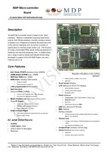
In this section, the core entities of the GLUE Schema are presented. They include the site concept (see Section 2.1) and an abstraction for the service concept (see Section 2.2). We also include the Computing Element and the Storage Element because of their relationship with the Site concept. In the major revision of the GLUE Schema they are expected to be a specialization of an higher level concept such as service or service group. Core
Site +UniqueID:string +Name:string +Description:string +UserSupportContact:string +SysAdminContact:string +SecurityContact:string +Location:string +Latitude:real32 +Longitude:real32 +Web:uri +Sponsor:string[*] +OtherInfo:string[*]
*
* *
Service
Cluster
StorageElement
+UniqueID:string +Name:string +Type:serviceType_t +Version:string +Endpoint:uri +Status:serviceStatus_t +StatusInfo:string +WSDL:uri * +Semantics:uri +StartTime:dateTime_xs_t +Owner:string[*] * * ServiceData +Key:string +Value:string
Created with Poseidon for UML Community Edition. Not for Commercial Use.
Figure 1: Core (red=deprecated, blue=new, black=unmodified)
4
2.1
Site
The site is an administrative concept used to aggregate a set of services and resources that are installed and managed by the same set of persons. It does not have any constraints as regards the Domain Name System (DNS) in the sense that multiple sites can be part of the same DNS domain or a single site can span multiple DNS domains.
Entity Site
Inherits from
Property UniqueID Name Description UserSupportContact
Type string string string string
Mult. 1 1 1 1
SysAdminContact
string
1
SecurityContact
string
1
Location
string
1
Latitude
real32
1
Longitude
real32
1
uri
1
Sponsor
string
*
OtherInfo
string
*
Web
Association Endpoint (Entity.Property) Service.UniqueID Cluster.UniqueID StorageElement.UniqueID
Description Set of resources that are installed and managed by the same organization/set of persons (N) Unit Description Unique Identifier of the Site (N) Human-readable name (N) Short description of this site (N) E-mail addresses of the support service. Syntax rule: ”mailto:” followed by a list of email addresses separated by a comma (e.g.: mailto: email1, email2, email3 (N) E-mail addresses of the system administrator. Syntax rule: ”mailto:” followed by a list of email addresses separated by a comma (e.g.: mailto: email1, email2, email3 (N) E-mail addresses of the security manager. Syntax rule: ”mailto:” followed by a list of email addresses separated by a comma (e.g.: mailto: email1, email2, email3 (N) Geographical location of this site (e.g., city, state, country) (N) Degree the position of a place north or south of the equator measured from −90 ◦ to 90 ◦ with positive values going north and negative values going south (N) Degree the position of a place east or west of Greenwich, England measured from −180 ◦ to 180 ◦ with positive values going east and negative values going west (N) The URI identifying a web page with more information about this site (N) VO sponsoring the site; the syntax should allow the expression of the percentage of sponsorship (N) This attribute is to be used to publish info that does not fit in any other attribute of the site entity. A name=value pair syntax or an XML structure are example of usage (N) Mult. Description * A site can hosts zero or more services * A site can hosts zero or more Clusters * A site can hosts zero or more Storage Element
The contact information attributes are to be used by applications. Other contact information can be placed in the web concerning the site which URL is in the Web attribute. Other contact information that should be searchable can be placed in the OtherInfo attribute.
5
2.2
Service
The Service entity captures all the common attributes to Grid Services and should be used as a base entity for the creation of service-specific schemas.
Entity Service
Inherits from
Owner string * Association Endpoint (Entity.Property) Site.UniqueID Service.UniqueID ServiceData.Key
Description An abstracted, logical view of actual software components that should be formally defined in terms of the messages exchanged between provider entity and requester entity (N) Unit Description Unique Identifier of this service (N) Human-friendly name (N) The service type (N) Version of the service: .. (N) Network endpoint for this service (N) Status of the service. String enumeration: OK, Warning, Critical, Unknown, Other (N) Textual explanation for the status of the service (N) URI of the WSDL describing the service (N) URL of detailed description (N) The timestamp related to last start time of this service (N) Owner of the service (e.g.: one or more VO’s) (N) Mult. Description 1 A Service is part of a Site (N) * A Service is in relationship with another service (N) * A Service has zero or more data specific info (N)
Entity Inherits from ServiceData Property Type Mult. Key string 1 Value string 1 Association Endpoint (Entity.Property) Service.UniqueID
Description Key=value pairs to publish service specific information(N) Unit Description Key identifying the type of data (N) Value (N) Mult. Description 1 A (key,value) pair related to a Service
Property UniqueID Name Type Version
Type string string serviceType t string
Mult. 1 1 1 1
Endpoint Status
uri serviceStatus t
1 1
StatusInfo WSDL Semantics StartTime
uri uri dateTime xs t
1 1 1 1
6
3
Computing Resources
In this section, we present a model for abstracting at the Grid level computing resources that are managed by different local resource managers . The Computing Element (CE) is a core concept of this model. It aims at describing the computing service that is offered to group of users or Virtual Organizations (VO). Typically, computing resources are contributed to the Grid as set of machines locally managed by systems such the Portable Batch System (PBS), Load Sharing Facility (LSF) or Condor. These systems offer different capabilities as regards flexibility in configuring and differentiating the access to the computing machines (i.e., worker nodes). All of them use queues to stage the requests and can be associated to a set of policies. Moreover, they offer scheduling functionalities to manage the fair share of the resources against the set of requests. The full set of features and policies for a given resource manager is typically much too large and complex to be represented in a reasonably compact schema. Further, different batch systems have features which vary qualitatively. The aim of the GLUE schema is therefore to model these systems in a way which gives a reasonable description for most practical uses, and which is capable of being implemented for all supported systems. This inevitably means that in some ways the model will be inaccurate; the main goal is usability in practice for common configurations. As a common abstraction, the Computing Element refers to the characteristics, resource set and policies of a single queue of the underlying management system. At the Grid level, computing capabilities appear as Computing Elements (i.e., set of job slots to which policies and status information are associated) that are reachable from a specific network endpoint. As local resource managers can be configured to assign group-specific policies to queues, different group of users can perceive a different state for a CE than the general one. For example, a CE may show free job slots when jobs for a particular VO will not run due to a VO-specific quota, or conversely the EstimatedResponseTime may be non-zero even though jobs for some VOs would start immediately. In order to deal with this possibility, we need to model the different states for different groups of users (typically on a per-VO basis or at a finer grain). This is accomplished by the VOView entity reporting state information specific to a group or VO. There are three extra attributes in both the CE and VOView entities introduced in this revision, namely ApplicationDir, DataDir and DefaulteSE, which are intended to support common usage in both LCG and Grid3. The first two are used for VO-specific areas mounted on all WNs which are used for application software and temporary data files respectively. The third is to specify a default SE for output files in the case that a job does not choose an SE explicitly; this will usually be one of the SEs specified in the CESEBind (see section 5). Finally, the attributes which previously had names referring to CPUs are being migrated to names referring to JobSlots, as this is clearer and is likely to cause less confusion (many systems run more than one job per CPU). Details of machines that offer the execution environment to jobs are described at a fine-grain level by the SubCluster entity. This provides also a summary description of homogeneous set of hosts. In this schema revision, the set of attributes that are used for the summary description have been isolated in the Host entity (see Fig. 2). This has not to be confused with the Host entity in Figure 7 of Section C. The separation is made in order to differentiate matchmaking-related attributes from the monitoring-related ones. Moreover, for backwards compatibility the two entities have the same name (this overlapping can be resolved during a major revision of the schema). A Cluster can be considered as a set of SubClusters. A SubCluster refers to a disjointed set of hosts. The following paragraphs are a suggestion for the syntax of the AccessControlPolicyBase.Rule and the VOView.AccessControlBaseRule attributes and for their use to represent or discover the authentication and authorization policies of a CE. Each user accessing the site presents a proxy certificate that contains the user identity. For VOMSenabled proxies, there will be also a Fully Qualified Attribute Name (FQAN) that is included in extended certificates and contains information about the VO/group and/or user role. The FQAN, like all the AccessControlBaseRule (or AccessControlPolicyBase.Rule) in the GLUE Schema, is a string where a series of identifier are separated by the ‘/’ (slash) character. Each identifier is a string where ‘/’ and ‘*’ should not be used. Normally, an FQAN identifies a group of users within a VO and the different levels separated by 7
‘/’ increase the granularity of the selection, starting from the VO itself. Case in these strings is important and comparison is case sensitive. An example is /myVO/mygroup/mysubgroup/myrole. The syntax vo:VONAME currently used for the AccessControlBase.Rule (LCG project) should be considered equivalent to /voname. A string with less level in the hierarchy includes each subgroup (e.g., /cms/production/group1 is included in /cms/production). The union of the user space covered by the strings in the AccessControlPolicyBase.Rule should cover all the possible FQAN of every user able to authenticate to the CE. The ‘*’ character could be used to identify any string within that level and allows more compact rule-sets. Each user allowed to use a CE will find at least one matching rule in the AccessControlPolicyBase.Rule. The matching FQAN-Rule is done through string comparison. A FQAN from a proxy matches any rule that is fully included in it (the /voname and all subgroups have to be in the FQAN in that exact order, that is the FQAN has to start with the string of the rule). A user coming with a proxy will be associated with the rule that provides the longest overlap. The following rules are suggested to find whether a user is allowed to use a CE and to understand when some VOView attributes should be considered instead of the general ones. (1) You will have to find all the matching rules (ordered according to their overlap with the FQAN); if there is no matching rule (or the rule is ‘/’, the default one), the user is likely not to be allowed to use the CE. (2) You will select the attributes in the VOView corresponding to the associated rule (these will describe the policy and the view of the resources the user should expect). (3) If some attribute is missing, that will be searched in the VOView of the next matching rule, up to the summary Computing Element attributes. A shortcut to find only if the user is authorized to use the CE consists in checking AccessControlPolicyBase.Rule instead of all the matching rules. Each CE administrator should use VOViews to provide accounting and/or policies for subgroup of users and identify these groups using the AccessControlBase rules of that VOView. The AccessControlPolicyBase entity associated with the CE will also be used to list users allowed to access the CE. A rule already listed in the AccessControlBase of a VOView should be repeated here even if is redundant (for backward compatibility). Example 1 shows an example of a rule set and how to find the attributes that apply to 2 incoming users. (1)
user1 membership: user2 membership:
/atlas/production/dc2 /atlas/production
CE.AccessControlBase.Rule: /atlas CE.AccessControlBase.Rule: /alice CE.AccessControlBase.Rule: /cms CE.State.FreeJobSlots: 100 CE.VOView.LocalID: ATLAS.production.dc2.view CE.VOView.AccessControlBaseRule: /atlas/production/dc2 CE.VOView.FreeJobSlots: 30 CE.VOView.LocalID: CMS.view CE.VOView.AccessControlBaseRule: /cms CE.VOView.FreeJobSlots: 30 The user1 will consider 30 free job slots, while the user2 will consider 100 free job slots. As user2 refers to the general section of the Computing Elements, slots can be shared among other VO’s/groups. Like all the attributes in the schema, AccessControl rules are a description of the Grid, specifically the CE. Even if it is expected to be correct and automatic scheduling mechanisms may use it, it is unlikely that the CE will use the GLUE Schema to enforce its authorization policies (it is more likely the opposite, that the Schema content presents the content of other softwares on the CE). For this reason users should not take it as a guarantee of the described policies (e.g. a user may not have access even if it is listed 8
in ComputingElementAccessControlPolicyBase.Rule or vice-versa) and system administrators should expect requests violating the posted limits and enforce them through other mechanisms (e.g., unlisted users sending requests).
3.1
Computing Element
A Computing Element is the common Grid abstraction for a queue of a system managing computing resources. The CE has associated a description of its static characteristics (Info), a status changing frequently (State), a general use policy (Policy), a set of authorized users groups (AccessControlPolicyBase), accounting information about special groups of users and special policies (VOViews) and job running on it (Jobs). The next tables describe all these Entities. Computing Element
Cluster +UniqueID:string +Name:string +TmpDir:string +WNTmpDir:string
+UniqueID:string +Name:string +InformationServiceURL:uri
is part of
is part of
ComputingElement 1..*
1..*
Info
Policy
+LRMSType:lrms_t +LRMSVersion:string +GRAMVersion:string +HostName:string +GatekeeperPort:int32 +JobManager:string +ContactString:string[*]
+MaxWallClockTime:int32 +MaxCPUTime:int32 +MaxTotalJobs:int32 +MaxRunningJobs:int32 +Priority:int32 +AssignedJobSlots:int32
+ApplicationDir:string +DataDir:string +DefaultSE:string
+UniqueID:string +Name:string +PhysicalCPUs:string +LogicalCPUs:string +TmpDir:string +WNTmpDir:string
AccessControlPolicyBase +Rule:string[*] * VOView
+TotalCPUs:int32
* State
Job
+Status:CEStatus +RunningJobs:int32 +WaitingJobs:int32 +TotalJobs:int32 +EstimatedResponseTime:int32 +WorstResponseTime:int32 +FreeJobSlots:int32
+LocalID:string +GlobaID:string +LocalOwner:string +GlobalOwner:string +Status:jobStatus_t +SchedulerSpecific:string
Location
SubCluster
+LocalID:string +AccessControlBaseRule:string[*] +RunningJobs:int32 +WaitingJobs:int32 +TotalJobs:int32 +FreeJobSlots:int32 +EstimatedResponseTime:int32 +WorstResponseTime:int32 +DefaultSE:uri +ApplicationDir:string +DataDir:string
*
+LocalID:string +Name:string +Version:string +Path:string Host +OperatingSystemName:string +OperatingSystemRelease:string +OperatingSystemVersion:string +ApplicationSoftwareRunTimeEnvironment:string[*] +ProcessorVendor:string +ProcessorModel:string +ProcessorVersion:string +ProcessorClockSpeed:int32 +ProcessorInstructionSet:string +ProcessorOtherDescription:string +NetworkAdapterInboundIP:boolean +NetworkAdapterOutboundIP:boolean +MainMemoryRAMSize:int32 +MainMemoryVirtualSize:int32 +ArchitecturePlatformType:string +ArchitectureSMPSize:int32 +BenchmarkSI00:int32 +BenchmarkSF00:int32
+FreeCPUs:int32
+FreeCPUs: int32
Created with Poseidon for UML Community Edition. Not for Commercial Use.
Figure 2: Computing Element (red=deprecated, blue=new, black=unmodified)
9
Entity Computing Element
Inherits from
Property UniqueID Name InformationServiceURL
Type string string uri
Mult. 1 1 1
Association Endpoint (Entity.Property) Info State Policy AccessControlBase.Rule Job.LocalID VOView.LocalID
Description Service that manages jobs and offers them execution environments provided by computing resources. The considered computing resources are those assigned to a single batch queue. Unit Description Unique Identifier for this computing element (U) The name of the underlying batch queue (U) Contact URI of the service providing for status and characteristics information (e.g., the URI of the MDS GRIS that is the primary source for the class instance information, this is useful to locate such an endpoint from a top-level GIIS) (U) Mult. Description 1 A Computing Element has general information 1 A Computing Element has state information 1 A Computing Element has policy information 1 A Computing Element has authorization policies * A Computing Element is managing this jobs * A Computing Element provides partitioned views of resources on a VO basis
10
Entity Info Property LRMSType
Type lrms t
Mult. 1
LRMSVersion GRAMVersion HostName GatekeeperPort JobManager
string string string int32 string
1 1 1 1 1
ContactString
string
*
TotalCPUs
int32
1
ApplicationDir
string
1
DataDir
string
1
uri
1
DefaultSE
Inherits from
Association Endpoint (Entity.Property) ComputingElement.UniqueID
Description General information about a Computing Element Unit Description Type of the underlying local resource management system (U) Version of the local resource management system (U) Version of Globus GRAM protocol (U) Host name of the machine running this service (U) Gatekeeper port (U) The job manager used by the gatekeeper (e.g.: jobmanager-pbs). Generally speaking, it is a string that allows to distinguish between different queues accessible using the same host and port. (N) String specifying how to contact the service. A default value can be HostName:GatekeerPort/Jobmanager. It identifies an endpoint for computing resources in a given protocol (usually GRAM) (N) Number of CPUs available to the service (it does not necessarily represents the total available resources in the underlying system as more computing elements can share the same computing resources (D) The path of the directory available for application installation. Typically a POSIX accessible disk space with transient to permanent allocation to the users (N) The path of a shared directory available for application data. Typically a POSIX accessible transient disk space shared between the Worker Nodes. It may be used by MPI applications or to store intermediate file the need further processing by local jobs or as staging area, specially if the Worker Node have no internet connectivity (N) Unique identifier of the default Storage Element. Unique identifier of the default Storage Element to be used to store files from jobs in the CE in cases where no destination SE is explicitly stated (N) Mult. Description 1 General information of a Computing Element
11
Entity State Property Status
Inherits from Type cestatus t
Mult. 1
EstimatedResponseTime
int32 int32 int32 int32
1 1 1 1
WorstResponseTime
int32
1
FreeJobSlots
int32
1
FreeCPUs
int32
1
RunningJobs WaitingJobs TotalJobs
Association Endpoint (Entity.Property) ComputingElement.UniqueID
Entity Policy Property MaxWallTime
Inherits from Type int32
Mult. 1
MaxCPUTime
int32
1
MaxTotalJobs MaxRunningJobs
int32 int32
1 1
Priority
int32
1
AssignedJobSlots
int32
1
Association Endpoint (Entity.Property) ComputingElement.UniqueID
Description Status description of a Computing Element Unit Description the queue status: ‘Queueing’ the queue can accept job submission, but can not be served by the scheduler; ‘Production’ the CE can accept job submissions and is served by a scheduler; ‘Closed’ The CE can not accept job submission and can not be served by a scheduler; ‘Draining’ the CE can not accept job submission, but can be served by a scheduler. (U) The number of jobs in running state (U) The number of jobs in waiting state (U) the number of jobs in any state (U) s Based on the accepted jobs, estimated time to last for a new job from the acceptance to the start of its execution (U) s Among the accepted jobs, the worst time from the job was accepted by the service to the start of its execution (U) Number of free job slots (sometime called logical CPUs), i.e., number of single-processor jobs which could be started if no other jobs are submitted and no jobs finish in the interim. This could be the size of the queue less the used resources, but a policy could influence this number (N) Number of free CPUs available to a scheduler (D, use FreeJobSlots instead) Mult. Description 1 Status of a Computing Element
Description Configuration policies associated to the Computing Element Unit Description min The maximum amount of wall clock time allowed to each job by the execution environment. Once this time is expired the job will most likely be killed or removed from the queue. (U) min The maximum CPU time allowed to each job by the execution environment (U) The maximum allowed number of jobs in the CE (U) The maximum allowed number of jobs in running state in the CE (U) The priority given to jobs in this CE. The lower the number, the higher the priority (U) Number of slots for jobs to be in running state (it represents the maximum number of single-processor jobs that can be running at a given time) (N) Mult. Description 1 Status of a Computing Element 12
Entity Job
Inherits from
Property LocalID
Type string
Mult. 1
GlobalID
string
1
GlobalOwner
string
1
ExecutionTarget
string
1
Status jobStatus t 1 SchedulerSpecific string 1 Association Endpoint (Entity.Property) ComputingElement.UniqueID
Entity Access Control Base Property Rule
Inherits from
Type string
Mult. *
Association Endpoint (Entity.Property) ComputingElement.UniqueID
Description Information about a job currently managed by the Computing Element Unit Description √ Batch job ID given by the batch system, unique within the CE (U) Batch job ID given by the grid system (should be a URI) (U) The owner of this job for the Grid system, e.g. the DN of the user submitting the job (U) The current target where the job is executed (typically the host name) (U) Status of the job: ‘queued’, ‘running’ (U) Scheduler specific info (U) Mult. Description 1 A job being managed by a Computing Element
Description Set of rules defining the authorization policies to this Computing Element Unit Description An authorization rule (see the discussion at the beginning of the section for a proposed syntax and usage) (U) Mult. Description 1 Set of authorizations for a Computing Element
13
Entity VOView Property LocalID
Inherits from Type string
Mult. 1
AccessControlBaseRule
string
*
RunningJobs
int32
1
WaitingJobs TotalJobs FreeJobSlots
int32 int32 int32
1 1 1
EstimatedResponseTime
int32
1
WorstResponseTime
int32
1
ApplicationDir
string
1
DataDir
string
1
DefaultSE
uri
1
FreeCPUs
int32
1
Association Endpoint (Entity.Property) ComputingElement.UniqueID
Description VO view of available resources of a Computing Element Unit Description Local identifier of the VO (or VO subgroup) within the CE (N) Set of authorizations for the Computing Element specific to this view (see the discussion at the beginning of the section for a proposed syntax and usage) (N) The number of jobs in running state on the CE for this VOview, that is the running jobs for the users selected by the AccessControlBaseRule). They can be considered also as the running jobs belonging to a specific VO (or VO subgroup) (N) The number of jobs in waiting state for this VOview (N) The number of jobs in any state for this VOview (N) Number of free job slots, i.e. number of single-processor jobs which could be started by users associated with this VOview if no other jobs are submitted and no jobs finish in the interim (N) s based on the accepted jobs, estimated time to last for a new job from the acceptance to the start of its execution (N) s Among the accepted jobs, the worst time lapse between the job acceptance by the service and the start of its execution (N) The path of the directory available for application installation. This directory must be available to programs using the normal file access primitives (open/read/write/close). The view provided by this directory on different hosts must be synchronized (N) The path of a shared directory available for application data (typically transient). This directory must be available to programs using the normal file access primitives (open/read/write/close). The view provided by this directory on different hosts must be synchronized (N) Unique identifier of the default Storage Element to be used to store files from jobs in the CE in cases where no destination SE is explicitly stated. This may be a SE close to the CE or a well connected VO default, e.g., gsiftp://myserver.local/data/rootdir/ (N) Number of free job slots, i.e., number of single-processor jobs which could be started if no other jobs are submitted and no jobs finish in the interim (D) Mult. Description 1 Computing Element to which this view is related
As regards the ApplicationDir and DataDir attributes, it should be considered that view provided by these directories on different hosts must be synchronized. For instance, f a host writes some content in a file, a read operation from a different host must be able to access that content. It may be necessary to call an explicit synchronization primitive, depending on the used technology. As regards ApplicationDir, the CE 14
may provide differentiated privileges, that allow read/write to VO’s software managers and read-only access to other VO use (suggested extra feature).
3.2
Cluster
A cluster gives a representation of a set of physical resources (hosts or Worker Nodes or computers) behind a CE. A cluster may be dedicated to a CE (no other access to those hosts is possible) or shared either with other CEs or with local users bypassing the Grid and using directly a job queue or the computers. A cluster is an heterogeneous set of resources (computers belonging to the same clusters may have different CPU, RAM and even different OS), while a subcluster, presented in the next section, is an homogeneous one.
Entity Cluster
Inherits from
Property UniqueID
Type string
Mult. 1
Name
string
1
TmpDir
string
1
WNTmpDir
string
1
Association Endpoint (Entity.Property) SubCluster.UniqueID ComputingElement.UniqueID Site.UniqueID
Description Set of machines providing computing power managed by a local management system Unit Description Unique ID associated to the cluster (typically refers to the host name of the machine where the LRMS runs (U))Unique ID associated to the cluster (typically refers to the host name of the machine where the LRMS runs (U)) Name of the cluster. It does not need to be unique and can be used as a human-readable name (U) The path of a temporary directory shared across worker nodes. This directory must be available to programs using the normal file access primitives (open/read/write/close) and possibly provide some lock mechanisms. The view provided by this directory on different hosts must be synchronized (e.g., if a host writes some content in a file, a read operation from a different host must be able to access that content. It may be necessary to call an explicit synchronization primitive, depending on the technology used). This directory may be used as shared space by programs running on multiple hosts (e.g. MPI) (N) The path of a temporary directory local to each Worker Node. This directory must be POSIX compliant. This will probably be the run directory for jobs running on that WN. Applications must be able to perform all the operations supported on local disks by that OS (e.g. open/read/write files or special files like pipes, create locks and change permissions). The Cluster or the CE may take care of providing an empty directory for the job and remove the directory once the job finished (N) Mult. Description 1..* A cluster can be decomposed in one or more subclusters 1..* A cluster offers Computing Elements A cluster is part of a site (N) 1
15
3.3
SubCluster
The SubCluster entity provides details of the machines that offer execution environments to jobs. It refers to homogeneous set of hosts as regards the selected attributes. In this schema revision, the set of attributes that are used for the summary description have been isolated in the Host entity (see Fig. 2). This has not to be confused with the Host entity in Figure 7 of Section C. The separation is made in order to differentiate matchmaking-related attributes from the monitoring-related ones. Moreover, for backwards compatibility the two entities have the same name (this overlapping can be resolved during a major revision of the schema). A Cluster can be considered as a set of SubClusters. A SubCluster refers to a disjointed set of hosts.
Entity SubCluster
Inherits from
Property UniqueID Name PhysicalCPUs LogicalCPUs
Type string string int32 int32
Mult. 1 1 1 1
Association Endpoint (Entity.Property) Cluster.UniqueID Location.LocalID Host
Entity Location
Inherits from
Property LocalID
Type string
Mult. 1
Name Version
string string
1 1
Path
string
1
Association Endpoint (Entity.Property) SubCluster.UniqueID
Description Information about an homogeneous set of hosts as regards a selected number of host attributes Unit Description Unique ID of the subcluster (U) Name of the the subcluster (U) The total number of real CPUs in the subcluster (N) The effective number of CPUs in the subcluster, including the effect of hyperthreading and the effects of virtualization due to the queuing system (N) Mult. Description 1 A subcluster is part of a cluster * A subcluster has associated a set of locations 1 A subcluster has associated a summary description of the offered execution environment
Description General mechanism that models name, version and path of installed software. It may be useful if some users (e.g., VO software managers) are allowed to modify directly these entries. Unit Description A local identifier for the location (suggested value: concatenation of Name and Version attributes separated by the + character) (N) A name for this location (e.g., VDT LOCATION) (N) Version, following the syntax adopted by that software (e.g., 1.3.6) (N) The related path. The strings $ApplicationDir, $DataDir, $DefaultSE, $TmpDir, and $WNTmpDir are reserved. They can be used only at the beginning of Path and are a reference to the directories pointed respectively by the ApplicationDir, DataDir, DefaultSE attributes in the VOView entity and by the TmpDir, WNTmpDir attributes in the Cluster entity (e.g., /opt/grid) (N) Mult. Description 1 A location is associated to a subcluster
16
Entity Host Property OperatingSystemName OperatingSystemRelease OperatingSystemVersion ProcessorModel ProcessorVersion ProcessorVendor ProcessorModel ProcessorVersion ProcessorClockSpeed ProcessorInstructionSet ProcessorOtherDescription
RAMSize VirtualSize NetworkAdapterOutboundIP NetworkAdapterInboundIP ArchitecturePlatformType
ArchitectureSMPSize BenchmarkSI00 BenchmarkSF00 App.Soft.RunTimeEnvironment
Inherits from Type string string string string string string string string int32 string
Mult. 1 1 1 1 1 1 1 1 1 1
string int32 int32 boolean
1 1 1 1
boolean string int32 int32 int32 string
1 1 1 1 1 *
Association Endpoint (Entity.Property) SubCluster.UniqueID
Description Summary description of the hosts part of the subcluster (N) Unit Description Name of the operating system (U) Release of the operating system (U) Version of the operating system (U) Processor model as defined by the vendor (U) Processor version (U) Name of the processor vendor (U) Processor model as defined by the vendor (U) Processor version (U) MHz The clock speed (U) The processor instruction set; use comma-separated values (e.g.: mmx,cisc) (U) MHz Other description for the processor (U) MByte The amount of RAM (U) MByte The amount of Virtual Memory (RAM+Swap) (U) Permission for direct outbound connectivity, even if limited (U) Permission for inbound connectivity, even if limited (U) Platform type of the host (U) number of physical CPUs in the host (U) SpecInt2000 (U) SpecFloat2000 (U) ApplicationSoftwareRunTimeEnvironment: environment variable associated to an installed software package (U) Mult. Description 1 Describing a subcluster
For measuring the attributes related to the operating system (i.e., name, release and version), we provide a recommendation for Linux-related environments. We suggest to rely on the commands related to the Linux Standard Base (LSB) specification[9]. In particular, we propose to use the command lsb release -d and to extract the output as follows: the name is given by the content between Description: and release; the release is given by the content between release and the character (; the version is given by the content between the character ( and the character ). For instance, if the output of the command /usr/bin/lsb release -d is Description: Fedora Core release 4 (Stentz), then the operating system related attributed should be filled as follows: GlueHostOperatingSystemName: Fedora Core, GlueHostOperatingSystemRelease: 4 and GlueHostOperatingSystemVersion: Stentz.
17
4
Storage Resources
In this section, we present a model for abstracting storage resources. Storage resources contributed to a Grid system can vary from simple disk servers to complex massive storage systems. These resources can be managed by different services, each of theme taking care of a certain management aspect (e.g., data access, quota management or space management). The Storage Element (SE) is the core concept of this model and identifies the group of services responsible for the storage resource. At the virtual level, the storage resource is abstracted using the concept of Storage Area that is assigned to a group of users or VO. Storage Element
StorageElement +UniqueID:string +InformationServiceURL:string +SizeTotal:int32 +SizeFree:int32 +Architecture:SEArch_t
StorageLibrary
+Port:int32 +StateCurrentIOLoad:string
ControlProcotol
Policy
StorageArea
+Quota:int32 +MinFileSize:int32 +MaxFileSize:int32 +MaxData:int32 +MaxNumFiles:int32 +MaxPinDuration:int32
+LocalID:string +Path:string +Type:SAType_t
+LocalID:string +Endpoint:uri +Type:controlProt_t * control +Version:string +Capability:string[*]
1..* manages
+Root:string
AccessProtocol access
+FileLifeTime:string
1..*
State +UsedSpace:int32 +AvailableSpace:int32
+LocalID:string +Endpoint:uri +Type:accessProt_t +Version:string +Capability:string[*] +SupportedSecurity:string[*] +Port:int +AccessTime:int
AccessControlBase +Rule:string[*]
Created with Poseidon for UML Community Edition. Not for Commercial Use.
Figure 3: Storage Element (red=deprecated, blue=new, green=modified, black=unmodified)
4.1
Storage Element
18
Entity Storage Element
Inherits from Service
Property UniqueID Name Architecture
Type string string SEArch t
Mult. 1 1 1
SizeTotal
int32
1
SizeFree
int32
1
InformationServiceURL
string
1
Port int32 1 StateCurrentIOLoad string 1 Association Endpoint (Entity.Property) StorageArea.LocalID ControlProtocol.UniqueID AccessProtocol.UniqueID Site.UniqueID
4.2
Description Abstraction for a storage resource. Group of services, protocols and data sources. Unit Description Unique Identifier of the Storage Element (U) Human-friendly name for the SE (U) Underlying architectural system category. String enumeration: disk, tape, multidisk, other (N) GByte the size of the storage capacity managed by this service (N) GByte the size of the storage capacity that is free for new files for any VO/user. (N) URL of the information service providing details for this SE (e.g., the URI of the MDS GRIS that is the primary source for the class instance information, this is useful to locate such an endpoint from a top-level GIIS) (U) (D) (D) Mult. Description * A storage element manages zero or more storage areas * A storage element groups zero or more control protocols 1..* A storage element offers one or more data access protocols 1 A storage element is part of a Site
Storage Area
The storage area is a logical portion of storage extent assigned to a VO. Storage areas can overlap the same physical space, thus having contention over the free space among different VO’s.
Entity StorageArea Property LocalID Root Path Type
Inherits from
Type string
Mult. 1
string string SAType t
1 1 1
Association Endpoint (Entity.Property) StorageElement.UniqueID
Description Portion of storage extent to which a uniform set of policies applies Unit Description Local Identifier of this area. It must be unique within the storage element. (N) The local directory that is the root of the area (D) Full path of the root directory for this storage area (N) Guarantee on the lifetime for the storage area. String enumeration: permanent, durable, volatile, other. (N) Mult. Description 1 A Storage Area is part of a Storage Element
19
Entity Policy Property Quota MinFileSize MaxFileSize MaxData
Inherits from
MaxNumFiles int32 1 Association Endpoint (Entity.Property) StorageArea.LocalID
Description Policy related to a storage area Unit Description KByte the quota assigned Byte minimum size for any single file (U) Byte maximum size for any single file (U) Byte maximum amount of data that may be stored by one job (U) Byte max number of files which may be stored by 1 job (U) s maximum time for a file to be pinned (U) s Lifetime policy to be applied to the contained files (Permanent, Durable or Volatile) (D) s (U) Mult. Description 1 A Policy is attached to a Storage Area
Type int32 int32 int32 int32
Mult. 1 1 1 1
MaxFileSize MaxPinDuration FileLifeTime
int32 int32 enum
1 1 1
Entity Inherits from State Property Type Mult. UsedSpace int32 1 AvailableSpace int32 1 Association Endpoint (Entity.Property) StorageArea.LocalID
Description Status info of the storage area Unit Description KByte The used space (the guaranteed quota is taken first) KByte The available space Mult. Description 1 A Status is for a Storage Area
In the major schema revision, the unit of measure for UsedSpace and AvailableSpace are expected to be changed to GByte.
4.3
Access Protocol
The AccessProtocol describes allowed ways to transfer files to and from an SE. Currently this includes gridftp, rfio (an HEP-specific protocol), and file which implies direct posix access, e.g. with NFS or AFS. The protocol is defined by its Type, which has an enumerated list of allowed values. The main attributes are the endpoint and the protocol version (note that in principle an SE could have multiple AccessProtocol objects for different versions of the same protocol). In addition there is a multi-valued string called ”Capability” which can be used to identify particular features, for example that a GridFTP server supports particular operations or that access is read-only. These values are not defined by the schema but would typically be defined across a grid project, and may in practice be agreed between projects. This usage is similar to the RunTimeEnvironment attribute for the CE.
20
Entity Access Protocol
Inherits from
Property LocalID
Type string
Mult. 1
Type accessProt t 1 Endpoint uri 1 Version string 1 Capability string * AccessTime int32 1 SupportedSecurity string * Port int32 1 Association Endpoint (Entity.Property) StorageElement.UniqueID
4.4
Description Protocol available to access/transport files in/from storage areas Unit Description Local Identifier, unique within a specific Storage Element instance (N) Type of access protocol (U) Network endpoint for this protocol (N) protocol version (U) Function supported by this access protocol (N) (D) The security features the protocol can deal with (D) (D) Mult. Description 1 Is part of a Storage Element
Control Protocol
The ControlProtocol is similar to the AccessProtocol, but orthogonal to it. Current protocols include srm and classic, although the latter is not a protocol as such but indicates that no control operations are supported and files should simply be read and written directly. Again an SE might support multiple versions of the same control protocol. There is again a Capability attribute which might be used to identify features like file pinning or advance reservation of space.
Entity Control Protocol
Inherits from
Property LocalID
Type string
Mult. 1
ControlProt t uri string string
1 1 1 *
Type Endpoint Version Capability
Association Endpoint (Entity.Property) StorageElement.UniqueID
4.5
Description Protocol available for the control and/or management of the storage resource (N) Unit Description Local Identifier, unique within a specific Storage Element instance (N) Type of control protocol (N) Network endpoint for this protocol (N) protocol version (N) Function supported by this control protocol (e.g., space reservation, pinning) (N) Mult. Description 1 Is part of a Storage Element
Storage Library
The storage library is deprecated and only the main entity is described. The file system is described in Section C
21
Storage Library
StorageLibrary +UniqueID:string +Name:string +InformationServiceURL:uri +ArchitectureType:string +PerformanceMAXIOCapacity:int32
FileSystem +Name:string +Root:string +Size:int32 +AvailableSpace:int32 +ReadOnly:boolean +Type:string
File
* FileStorage Mount
*
+Name:string +Size:int +CreationDate:datetime +LastModified:datetime +LastAccessed:datetime +Latency:int +LifeTime:datetime +Owner:string
*
RemoteFileSystem
+ DirectoryContainsFile
LocalFileSystem
0..1 0..1
Directory
0..1 export
*
Created with Poseidon for UML Community Edition. Not for Commercial Use.
Figure 4: Storage Library (red=deprecated, blue=new, black=unmodified)
Entity Inherits from StorageLibrary Property Type Mult. UniqueID string 1 Name string 1 InformationServiceURL string 1 ArchitectureType string 1 PerformanceMaxIOCapacity int32 1 Association Endpoint (Entity.Property) FileSystem.Name
Description The machine providing for the storage service (D) Unit Description Unique Identifier (D) Name (D) InformationServiceURL (D) Architecture (D) IO Capacity (D) Mult. Description 1..* A Storage Library has one or more file systems
22
5
Computing and Storage relationship
Computing and Storage Elements may have relationships implied by the presence of a shared file system (e.g., NFS-mount). Moreover, it is desirable to be able to express a preference relationship among them. Both type of relationships are useful to be discovered from the GIS, since they can be used during Grid-level scheduling. These relationships are intended to be captured by the CESEBind concept. Unfortunately this was designed some time ago and several problems have since come to light; this area will be addressed in the next major schema revision. At present several points need to be borne in mind. The CESEBind relation (also known as a ”close SE”) has traditionally been used in three separate ways: as a way of choosing a CE based on proximity to input files, as a default place to store output files, and as a representation of shared authorisation between CE and SE for rfio and NFS access - with a mount point (AccessPoint) attribute included for the latter. The first use was intended to be replaced in the longer term by dynamic network monitoring, but this has so far not appeared so this remains the main way to schedule jobs on the basis of fast access to input files. Close SEs should therefore be specified on this basis, and hence may include SEs at different sites if a sufficiently fast network connection is available. The second use is now largely superseded by the explicit DefaultSE attribute in the CE and VOView objects. However, if the default SE is unusable for some reason, other SEs listed in the CESEBind would still be a good choice as a fallback on the basis of fast access. The third use, direct file access via NFS mounts, is problematic for various reasons and has been dropped by LCG for the time being. The current schema can be used with some limitations, but if continued support for NFS mounts is required a more elaborate schema will be needed. There is no explicit representation of ”local” access for e.g. rfio. There are also two technical issues to be aware of. One is that in the past the AccessPoint in the CESEBind was required for ”classic” SEs even without an NFS mount, because it was also used to specify the storage area on the SE. This schema revision removes this requirement by introducing the new SAPath attribute in the SE information, which gives the full file path of the storage area, as opposed to the old SARoot which only contained the VO-specific part. The second point is that the CESEBind is generally published with the CE information. Within a site this is not generally a problem, but in some cases it may be desirable to specify relations between CEs and SEs at different sites, and in this case the relation will be under the control of the site running the CE. It is also usually true that if the CE is down the CESEBind will not be published, and conversely that if the SE is down and the CE is not the CESEBind will still be present, which may represent a degree of inconsistency. CESEBind
CESEBind +MountInfo:string +AccessPoint:string +Weight:int32 ComputingElement
StorageElement
1..* 1..*
Created with Poseidon for UML Community Edition. Not for Commercial Use.
Figure 5: Computing Element/Storage Element Relationship (red=deprecated, blue=new, green=modified, black=unmodified)
23
Entity Bind Property MountInfo
Inherits from Type string
Mult. 1
Weight
uint32
1
AccessPoint string 1 Association Endpoint (Entity.Property) ComputingElememt.UniqueID StorageElement.UniqueID
Description Association Class between CE and SE describing preference Unit Description Information about the name of the mount directory common to worker nodes part of the Computing Element and the exported directory from the Storage Element. Its value is a pair of path names (e.g.: /mounted/dir,/exported/dir). If this information is available in an environment variable common to all worker nodes, then the value of this attribute can be the name of such variable (starting with $)(N) It expresses a preference when multiple SE are bound to a CE; the higher, the better. Default is zero (D) Mult. Description * The Computing Element * The Storage Element
24
6
Change Log
Date 28 Oct 04 17 Feb 05
Version 1 2
21 Feb 05 14 Mar 05 16 Mar 05 6 Apr 05
3 5 6 7
22 Jul 05 24 Sep 05
8 9
03 Dec 05
final
A
Description Initial Draft published Added more issues from both LCG and Grid3/OSG Added extensions based on the Grid3/OSG Added outcome from f2f meeting Added comments from Marco’s first review Applied changes as decided in the 31 march phoneconf minor editorial changes included contributions from Marco, Steve and Stephen small editorial changes, added info about operating system, changed relationship from siteCE to site-Cluster
Contributor Sergio Andreozzi LCG, Grid3/OSG Grid3/OSG
Description of the template
In order to enrich the UML Class Diagrams with additional information, additional tables are associated to each defined class. The structure of each table contains three parts. The first part (1) refers to the whole entity and presents the entity name, the entity from which it inherits (if any) and the description of what the entity is. The second part (2) refers to the attributes that are defined in the UML Class diagram; for each of them, the following properties are described: the attribute name as defined in the UML Class diagram, the data type as defined in B, the multiplicity concerning how many values for the attribute are allowed (* means zero or more), the unit of measurement and the attribute description with a letter specifying the status of the attribute as regards the previous schema version (N for new, U for unmodified and D for deprecated). The third part (3) refers to the associations (association, composition, aggregation or association class) that the class may hold with other classes. For each association, the associated class endpoint is described in terms of the endpoint name, the multiplicity (i.e., the number of instances of the associated class that are allowed) and a description. This is the template as described above:
Entity Property
Inherits from Type
Mult.
Association Endpoint (Entity.Property)
B
Description Unit
Description
Mult.
Description
Datatypes
In Figure 6, the set of datatypes that are used in this information model are presented. The dateTime xs t is a timestamp compliant to the XML Schema definition [10]. Where clearly stated, refers to [8] for the complete set of values for the enumeration.
25
DataTypes
>
>
>
>
serviceStatus_t
uri
string
uint32
+OK:string +warning:string +critical:string +unknown:string
−MaxLen: >
>
int32
boolean
> SEArch_t +disk:string +tape:string +multidisk:string +other:string > SAType_t +volatile:string +durable:string +permanent:string +other:string
>
>
real32
unixtime_t
>
>
jobStatus_t
dateTime_xs_t
> cestatus_t +queueing:string +production:string +closed:string +draining:string
>
+queued:string +running:string
lrms_t +other:string
> serviceType_t +other:string
controlProt_t see GLUE Schema webpage for the specification of the enumeration
+other:string
> accessProt_t +other:string
Created with Poseidon for UML Community Edition. Not for Commercial Use.
Figure 6: Datatypes
26
C
Host
This section provides the modeling of a generic host entity. This entity has been decoupled from the generic CE/Cluster/SubCluster hierarchy as the former is mainly used for functional monitoring while the latter is used mainly for matchmaking. Host
Host +UniqueID:uri +Name:uri +UpTime:unixtime_t
OperatingSystem
Architecture MainMemory +RAMSize:int32 +RAMAvailable:int32 +VirtualSize:int32 +VirtualAvailable:int32
Load +Last1Min:int32 +Last5Min:int32 +Last15Min:int32
NetworkAdapter
+SI00:int32 +SF00:int32
+Release :string +Version :string
File
ApplicationSoftware
1..*
+RunTimeEnvironment:string[*]
FileSystem StorageDevice 1..*
+Vendor:string +Model:string +Version:string +ClockSpeed:int32 +InstructionSet:string +OtherProcessorDescription:string +CacheL1:int32 +CacheL1I:int32 +CacheL1D:int32 +CacheL2:int32 ProcessorLoad
Benchmark
+Name:string +IPAddress:string +MTU:int32 +InboundIP:boolean +OutboundIP:boolean
Processor
+Last1Min:int32 +Last5Min:int32 +Last15Min:int32
+Name :string
+PlatformType:string +SMPSize:int32 +SMTSize:int32
+Name:string +Type:string +TransferRate:int32 +Size:int32 +AvailableSpace:int32
1..*
+Name:string +Root:string * file storage +Size:int32 +AvailableSpace:int32 +ReadOnly:boolean 0..1 +Type:string
1..*
*
0..1 Directory
* resides on
*
+Name:string +Size:int32 +CreationDate:unixtime_t +LastModified:unixtime_t +LastAccessed:unixtime_t +Latency:int32 +LifeTime:int32 +Owner:string
mount
0..1
StoragePartition +Name:string +Size:string +ReadRate:int32 +WriteRate:int32
* RemoteFileSystem
LocalFileSystem
0..1
SMPLoad +Last1Min:int32 +Last5Min:int32 +Last15Min:int32
Created with Poseidon for UML Community Edition. Not for Commercial Use.
Figure 7: Host (red=deprecated, blue=new, black=unmodified)
27
export
Entity Inherits from Host Property Type Mult. UniqueID string 1 Name string 1 UpTime int32 1 Association Endpoint (Entity.Property) Architecture MainMemory NetworkAdapter Load Processor OperatingSystem Benchmark ApplicationSoftware FileSystem.Name StorageDevice.Name StoragePartition.Name
Description An elementary computing system Unit Description Unique ID of the host (U) Name of the host (U) s UpTime since last OS boot (N) Mult. Description 1 The host has an architecture 1 The host has a main memory 1..* The host has one or more network adapters 1 The host has load status 1 The host has processors 1 The host has an operating system 1 The host has benchmark information 1 The host has application software installed 1..* The host has one or more file systems 1..* The host has one or more storage devices 1..* The host has one or more storage partitions
Entity Architecture Property PlatformType SMPSize SMTSize
Association Endpoint (Entity.Property) Host.UniqueID
Description Information about the host architecture Unit Description Platform type of the host (N) number of physical CPUs in the host (N) number of logical CPUs in the host. If the CPUs support the Simultaneous Multi Threading (a.k.a., HyperThreading) technology and this is enabled, the logical CPUs have to be advertised (N) Mult. Description 1 Architecture information for an host
Entity Inherits from MainMemory Property Type Mult. RAMSize int32 1 RAMAvailable int32 1 VirtualSize int32 1 VirtualAvailable int32 1 Association Endpoint (Entity.Property) Host.UniqueID
Description Information about the main memory of the host Unit Description MByte The amount of RAM (N) MByte The amount of free RAM (N) MByte The amount of Virtual Memory (RAM+Swap) (N) MByte The amount of free Virtual Memory (N) Mult. Description 1 Main memory information for an host
Inherits from Type string int32 int32
Mult. 1 1 1
28
Entity NetworkAdapter Property Name IPAddress MTU
Inherits from Type string string int32
Mult. 1 1 1
OutboundIP boolean 1 InboundIP boolean 1 Association Endpoint (Entity.Property) Host.UniqueID
Entity Processor Property Vendor Model Version ClockSpeed InstructionSet
Inherits from Type string string string int32 string string
OtherProcessorDescription
Mult. 1 1 1 1 1 1
CacheL1 int32 1 CacheL1I int32 1 CacheL1D int32 1 CacheL2 int32 1 Association Endpoint (Entity.Property) Host.UniqueID
Entity ProcessorLoad Property Last1Min
Inherits from Type int32
Mult. 1
Last5Min
int32
1
Last15Min
int32
1
Association Endpoint (Entity.Property) Host.UniqueID
Description Information about the network adapters of the host Unit Description The network adapter name (U) Assigned IP address (U) byte the Maximum Transmission Unit (MTU) size for the LAN to which the network card is attached (U) permission for outbound connectivity (U) permission for inbound connectivity (U) Mult. Description 1..* A network adapter is part of an host
Description Information about the processor of the host Unit Description Name of the processor vendor (U) Processor model as defined by the vendor (U) Processor version (U) MHz The clock speed (U) Processor instruction set (U) Other processor description, to be used for extra information not covered by the schema (U) KByte first-level unified cache size of the processor (U) KByte first-level instruction cache size of the processor (U) KByte first-level data cache size of the processor (U) KByte second-level unified cache size of the processor (U) Mult. Description 1 The processor is part of an host
Description Information about the load of the machine (D) Unit Description The average number of process ready to run during the last 1 minute (the value is times 100 to be meaningfully represented as an integer) (D) The average number of process ready to run during the last 5 minutes (the value is times 100 to be meaningfully represented as an integer) (D) The average number of process ready to run during the last 15 minutes (the value is times 100 to be meaningfully represented as an integer) (D) Mult. Description 1 The load of the host
29
Entity SMPLoad Property Last1Min
Inherits from Type int32
Mult. 1
Last5Min
int32
1
Last15Min
int32
1
Association Endpoint (Entity.Property) Host.UniqueID
Entity Load Property Last1Min
Inherits from Type int32
Mult. 1
Last5Min
int32
1
Last15Min
int32
1
Description Information about the load of a processor (D) Unit Description The average number of process ready to run during the last 1 minute (the value is times 100 to be meaningfully represented as an integer) (D) The average number of process ready to run during the last 5 minutes (the value is times 100 to be meaningfully represented as an integer) (D) The average number of process ready to run during the last 15 minutes (the value is times 100 to be meaningfully represented as an integer) (D) Mult. Description 1 The processor is part of an host
Association Endpoint (Entity.Property) Host.UniqueID
Description Information about the load of the host Unit Description average of the sum of the run queue length and the number of jobs currently running on the CPUs in the last minute (the value is times 100 to be meaningfully represented as an integer) (N) average of the sum of the run queue length and the number of jobs currently running on the CPUs in the last 5 minutes (the value is times 100 to be meaningfully represented as an integer) (N) average of the sum of the run queue length and the number of jobs currently running on the CPUs in the last 15 minutes (the value is times 100 to be meaningfully represented as an integer) (N) Mult. Description 1 The load of the host
Entity Inherits from Benchmark Property Type Mult. SI00 int32 1 SF00 int32 1 Association Endpoint (Entity.Property) Host.UniqueID
Description Information about benchmark for the host Unit Description SpecInt2000 (U) SpecFloat2000 (U) Mult. Description 1 The benchmarks of the host
30
Entity Inherits from OperatingSystem Property Type Mult. Name string 1 Release string 1 Version string 1 Association Endpoint (Entity.Property) Host.UniqueID
Description Information about the operating system of the host Unit Description Name of the operating system (U) Release of the operating system (U) Version of the operating system (U) Mult. Description 1 The operating system information of the host
Entity ApplicationSoftware
Description Information about the application software available in the host Unit Description environment variable associated to an installed software package (U) Mult. Description 1 The runtime environment information of the host
Property RunTimeEnvironment
Inherits from
Type string
Mult. *
Association Endpoint (Entity.Property) Host.UniqueID
Entity Inherits from StorageDevice Property Type Mult. Name string 1 Type string 1 Size int32 1 TransferRate int32 1 AvailableSpace int32 1 Association Endpoint (Entity.Property) Host.UniqueID StoragePartition.Name
Description Information about a storage device in the host Unit Description Name of the storage device Type of storage device (U) MByte Size of the storage device (U) Maximum transfer rate for the device (U) MByte Space available (D) Mult. Description 1 The storage device of the host * The storage device can hosts zero or more storage partitions
Entity Inherits from StoragePartition Property Type Mult. Name string 1 Size int32 1 ReadRate int32 1 WriteRate int32 1 Association Endpoint (Entity.Property) Host.UniqueID StorageDevice.Name
Description Information about a storage partition in the storage device Unit Description Name of the storage partition (N) Mbytes Size (N) Mbytes Number of megabytes write per second (N) Mbytes Number of megabytes read per second (N) Mult. Description 1 The storage partition is part of the host 1..* The storage partition can span one or more storage devices The Storage Partition can be associated to a file sys0..1 tem
FileSystem.Name
31
Entity FileSystem Property Name Root
Inherits from
Size int32 1 AvailableSpace int32 1 ReadOnly boolean 1 Type string 1 Association Endpoint (Entity.Property) Host.UniqueID StoragePartition.Name Directory.Name File.Name
Description Information about a file system Unit Description Name of the file partition (U) path name or other information defining the root of the file system (U) Mbyte Size of the file system (U) Mbyte Available space in the file system (U) Read-only or read-write capabilities (U) Type of file system (U) Mult. Description 1 The storage partition of the host 1 The file system resides on a storage partition 0..1 The file system can be mount to one directory * The file system contains zero or more files
Entity LocalFileSystem Property
Description Information about a local file system (U) Unit Description
Type string int32
Mult. 1 1
Inherits from FileSystem Type Mult.
Association Endpoint (Entity.Property) Directory.Name
Entity RemoteFileSystem Property
Inherits from FileSystem Type Mult.
Association Endpoint (Entity.Property)
Entity Inherits from File Property Type Mult. Name string 1 Size int32 1 CreationDate unixtime t 1 LastModified unixtime t 1 1 LastAccessed unixtime t Latency int32 1 LifeTime int32 1 Owner string 1 Association Endpoint (Entity.Property) Directory.Name FileSystem.Name
Mult. *
Description The file system can exports zero or more directories
Description Information about a remote file system (U) Unit Description Mult.
Description
Description Information about a file Unit Description Name of the file (D) KByte File size (D) s File creation date and time (D) s Last modified date and time (D) s Last accessed date and time (D) Time taken to access file in seconds (D) s Lifetime left for this file (-1 if never expires) (D) File owner Mult. Description 0..1 The file can be part of a directory * The file is part of a file system
32
Entity Directory Property
Inherits from File Type Mult.
Association Endpoint (Entity.Property) File.Name LocalFileSystem.Name
Description Information about a directory (D) Unit Description Mult. * 0..1
Description The directory contains zero or more files (D) The directory can be exported from the local file system (D)
33
References [1] K. Czajkowski, S. Fitzgerald, I. Foster, and C. Kesselman. Grid Information Services for distributed resource sharing. In IEEE Press, editor, Tenth IEEE International Symposium on High-Performance Distributed Computing (HPDC-10), Aug 2001. [2] GLUE Schema collaboration. http://infnforge.cnaf.infn.it/glueinfomodel/.
The
GLUE
Schema
homepage.
[3] The Globus Alliance. Glue Schema page. http://www.globus.org/mds/glueschemalink.html. [4] LHC Computing Grid. LCG 2 Information Reference. http://grid-deployment.web.cern.ch/griddeployment//documentation/public/gis/InformationModel /html/InformationModel /index.html. [5] M. Mambelli and the Grid2003 Project. Grid3 information directory schema, Sep 2003. http://www.ivdgl.org/documents/document server/ show docs.php?series=grid3&category=tech&id=765. [6] S. Burke, L. Field, M. Litmaath, D. Smith, J. Casey, J.P. Baud, and J. plon. LCG Proposal for a Minor Upgrade to the GLUE Schema, Jan http://infnforge.cnaf.infn.it/docman/view.php/9/72/GLUE%20proposal%20final.doc.
Tem2005.
[7] B. K´onya. The NorduGrid/ARC Information System - technical description and reference manual. http://cvs.nordugrid.org/cgi-bin/cvsweb/∼checkout∼/nordugrid/doc/informationsystem/arc infosys.pdf?content-type=application/pdf. [8] GLUE schema, datatypes definition. http://infnforge.cnaf.infn.it/glueinfomodel/index.php/Spec/V12. [9] Linux Standard Base Specification. http://www.linuxbase.org/. [10] P.V. Biron and A. Malhotra. XML Schema Part 2: Datatypes Second Edition, 2004. W3C Recommendation 28 October 2004, http://www.w3.org/TR/xmlschema2/]dateTime.
34