Please write to UNU/IIST at P.O. Box 3058, Macau or visit UNU/IIST home page: http://www.iist.unu.edu ... 2.2.1 Formal speci cation of the Class Adapter pattern .
UNU/IIST International Institute for Software Technology
GoF Structural Patterns: A Formal Speci cation Andres Pablo Flores and Richard Moore August 2000
UNU/IIST Report No. 207
T
UNU/IIST and UNU/IIST Reports UNU/IIST (United Nations University International Institute for Software Technology) is a Research and
Training Centre of the United Nations University (UNU). It is based in Macau, and was founded in 1991. It started operations in July 1992. UNU/IIST is jointly funded by the Governor of Macau and the governments of the People's Republic of China and Portugal through a contribution to the UNU Endownment Fund. As well as providing two-thirds of the endownment fund, the Macau authorities also supply UNU/IIST with its o�ce premises and furniture and subsidise fellow accommodation.
The mission of UNU/IIST is to assist developing countries in the application and development of software technology. UNU/IIST contributes through its programmatic activities:
1. Advanced development projects, in which software techniques supported by tools are applied, 2. Research projects, in which new techniques for software development are investigated, 3. Curriculum development projects, in which courses of software technology for universities in developing countries are developed, 4. University development projects, which complement the curriculum development projects by aiming to strengthen all aspects of computer science teaching in universities in developing countries, 5. Courses, which typically teach advanced software development techniques, 6. Events, in which conferences and workshops are organised or supported by UNU/IIST, and 7. Dissemination, in which UNU/IIST regularly distributes to developing countries information on international progress of software technology. Fellows, who are young scientists and engineers from developing countries, are invited to actively participate in all these projects. By doing the projects they are trained. At present, the technical focus of UNU/IIST is on formal methods for software development. UNU/IIST is an internationally recognised center in the area of formal methods. However, no software technique is universally applicable. We are prepared to choose complementary techniques for our projects, if necessary. UNU/IIST produces a report series. Reports are either Research R , Technical T , Compendia C or Administrative A . They are records of UNU/IIST activities and research and development achievements.
Many of the reports are also published in conference proceedings and journals.
Please write to UNU/IIST at P.O. Box 3058, Macau or visit UNU/IIST home page: http://www.iist.unu.edu, if you would like to know more about UNU/IIST and its report series. Zhou Chaochen, Director | 01.8.1997 { 31.7.2001
UNU/IIST International Institute for Software Technology
P.O. Box 3058 Macau
GoF Structural Patterns: A Formal Speci cation Andres Pablo Flores and Richard Moore Abstract GoF structural patterns represent standard techniques in object-oriented design of composing classes and objects to form larger structures. The GoF catalogue describes, using a standard but informal notation, seven such patterns, each of which captures di�erent structural aspects. In this paper, we present an analysis of the essential components and properties of these patterns, and we specify these properties formally using a formal model of a general object-oriented design which was developed in earlier work as the basis for the speci cation. We also give an example of how to use these speci cations in order to check whether a subset of a particular design matches a particular structural pattern.
Andres Pablo Flores is a Fellow of UNU/IIST (November 1999 to August 2000), on leave from Comahue University, Neuquen, Argentina, where he is an Assistant Teacher. His research interests are focused on the software engineering disciplines, mainly on those related with software analysis and design. He is currently working on the combination of formal and informal methods and its application in a real domain. Richard Moore is a Research Fellow on the sta� of UNU/IIST, a position he took up on October 1st 1995. He has an M.A. in mathematics from the University of Cambridge and a Ph.D. in physics from the University of Manchester. He has been engaged in computing science research in the eld of formal methods since 1985, a large part of which was carried out in the formal methods group at Manchester University. He has written several papers on formal methods and is co-author of two books on formal methods { mural: a Formal Development Support System; and Proof in VDM: A Practitioner's Guide. He has also worked for the Defence Research Agency in Malvern, UK, on various formal methods projects, both as a consultant and as a full-time member of sta�.
Copyright c 2001 by UNU/IIST, Andres Pablo Flores and Richard Moore
Contents
i
Contents
1 Introduction 2 The Adapter Pattern
2.1 Properties of the Adapter Pattern . . . . . . . . . . . . . . 2.2 Formalising the Adapter Pattern . . . . . . . . . . . . . . . 2.2.1 Formal speci cation of the Class Adapter pattern . . 2.2.2 Formal speci cation of the Object Adapter pattern .
. . . .
. . . .
. . . .
. . . .
. . . .
. . . .
. . . .
. . . .
. . . .
. . . .
. . . .
1 3
. 4 . 6 . 7 . 12
3 The Bridge Pattern
16
4 The Composite Pattern
22
5 The Decorator Pattern
32
6 The Facade Pattern
40
7 The Flyweight Pattern
48
8 The Proxy Pattern
58
9 Application of the Decorator Pattern 10 Conclusions A Speci cation of the Decorated Text Editor
67 72 73
3.1 Properties of the Bridge Pattern . . . . . . . . . . . . . . . . . . . . . . . . . . . 16 3.2 Formalising the Bridge Pattern . . . . . . . . . . . . . . . . . . . . . . . . . . . . 17
4.1 Properties of the Composite Pattern . . . . . . . . . . . . . . . . . . . . . . . . . 23 4.2 Formalising the Composite Pattern . . . . . . . . . . . . . . . . . . . . . . . . . . 24
5.1 Properties of the Decorator Pattern . . . . . . . . . . . . . . . . . . . . . . . . . 32 5.2 Formalising the Decorator Pattern . . . . . . . . . . . . . . . . . . . . . . . . . . 34
6.1 Properties of the Facade Pattern . . . . . . . . . . . . . . . . . . . . . . . . . . . 41 6.2 Formalising the Facade Pattern . . . . . . . . . . . . . . . . . . . . . . . . . . . . 42
7.1 Properties of the Flyweight Pattern . . . . . . . . . . . . . . . . . . . . . . . . . . 49 7.2 Formalising the Flyweight Pattern . . . . . . . . . . . . . . . . . . . . . . . . . . 51
8.1 Properties of the Proxy Pattern . . . . . . . . . . . . . . . . . . . . . . . . . . . . 58 8.2 Formalising the Proxy Pattern . . . . . . . . . . . . . . . . . . . . . . . . . . . . 60 8.3 Virtual Proxy . . . . . . . . . . . . . . . . . . . . . . . . . . . . . . . . . . . . . . 65
Report No. 207, August 2000
UNU/IIST, P.O. Box 3058, Macau
Introduction
1
1 Introduction Designing is a di�cult task. The e�ciency of the design process needs to be improved in order to avoid wasting time and e�ort which only translate to more costly software development. One important step in this direction is to reuse design work that has already been done, and which is therefore proven to work well and can thus serve as certi cation of a new design. This requires abstracting out pieces of design that have been found to recur in previous designs. This is still a very hard task, however, even for expert designers. One approach to reuse in which there is widespread interest is design patterns. Each design pattern describes a generic solution to some problem which is commonly encountered in di�erent contexts, and the solution to a particular problem can be obtained by customising the generic pattern design [8, 16]. Patterns thus summarise the experience of designers working on similar problems in di�erent contexts and represent proven solutions for solving these problems. The solution proposed by a pattern involves a sort of structure which properly balances the numerous competing concerns or \forces" which are present in a certain context [1]. Design patterns convey regularities, plans, aspects, or abstractions of programs rather than concrete instances. Applying a design pattern allows some aspects in a system structure to vary independently of others, emphasising exibility in the whole system, because the structure of the pattern results in a high degree of adaptability [15]. In addition, patterns are described in a general and abstract way which helps designers recognise an architecture matching the pattern when working on a particular concrete application. Thus, most design patterns have an unlimited number of implementations, usually in various programming languages and numerous application domains [5]. Their use can therefore lead to a more rapid understanding of a particular design problem and hence a more rapid completion of the design, which means saving time and e�ort in the whole development [4]. Design patterns became popular with the publication of the GoF catalogue1 [7], which introduced a body of literature for design problems in software development, similar to the common vocabularies which are fundamental in any science or engineering discipline for expressing and relating its concepts [1]. The patterns thus help to create a shared language for communicating insight and experience about particular design problems and their possible solutions. GoF design patterns are described by means of natural language narrative and a graphical notation which is based on an extension of OMT (Object Modelling Technique [13]). Although these are good tools for representing the essence of each pattern intuitively, it is not su�ciently precise to allow a designer to demonstrate conclusively that a particular problem matches a particular pattern or that a proposed solution is consistent with a particular pattern. The notation also makes it di�cult to be certain that the patterns used are meaningful and contain no inconsistencies. It is therefore extremely di�cult to give any meaningful certi cation of the correctness of software developed using patterns. 1 GoF means Gang of Four, as the authors of this catalogue are commonly referred to. Report No. 207, August 2000
UNU/IIST, P.O. Box 3058, Macau
Introduction
2
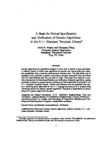
Providing a more precise description of patterns can help designers know more clearly not only when and how a particular pattern can be applied but also that it has been applied correctly. It can also help to improve understanding of the patterns and to avoid inconsistencies, ambiguities and incompleteness which are inherent in the graphical/textual notation. To this end, a formal model of a generic object-oriented design has been developed [6] and speci ed using the RAISE speci cation language RSL [11]. This formalises the various components which are found in the extended OMT notation used in the GoF catalogue and also separates the design from the patterns. Various common properties of the GoF design patterns are then speci ed in this model as generic RSL functions, and these, appropriately instantiated and combined, can be used to formalise the properties of the patterns. The veri cation that a design matches a pattern is then done by rst relating or binding the names of the entities (classes, methods, state variables, and parameters) in (a subset of) the design with the names of corresponding entities appearing in the particular pattern, then checking that all the properties of the pattern are satis ed by the corresponding entities in the design. Figure 1 illustrates how the renaming map binds a (subset of a) design to a particular pattern { the bindings are denoted by the dotted lines. As can be seen in this gure, there can be some
exibility in the way these bindings are formed. For example, a class hierarchy in the pattern can correspond to a more complicated hierarchy in the design where there are intermediate classes which play no role in the pattern, and operations can be de ned or implemented in a superclass of the class corresponding to the one in which they appear in the pattern. Pattern Level
PatClass1
PatRelation PatClass2
PatClass3 PatOperation()
UDClass1
UDClass4 UDOperation()
UDClass2
do something
do something
UDRelation1 UDClass5
UDClass3
UDRelation2
UDClass6
User Design Level
Figure 1: Binding of Design and Pattern Levels GoF design patterns are classi ed in [7] according to two criteria: purpose and scope. A pattern's purpose re ects what the pattern does, and may be either creational, structural, or behavioural, while the scope indicates whether the pattern applies primarily to classes or to objects, and thus Report No. 207, August 2000
UNU/IIST, P.O. Box 3058, Macau
The Adapter Pattern
3
may be either class or object. Nine of the eleven behavioural patterns have already been speci ed as described above [12], and parallel work is addressing the creational patterns [2]. In this report we apply the same techniques to the GoF structural patterns. Structural patterns are concerned with how classes and objects are composed to form larger structures. In general, structural class patterns use inheritance to compose interfaces or implementations, while structural object patterns describe ways to compose objects so as to realize new functionality. Object composition gives some added exibility because the composition can be changed at run-time, which is impossible with static class composition, so the scope of most structural patterns is in fact object. Patterns in general encapsulate aspects of a design that can vary, with individual patterns relating to the variation of di�erent aspects. A designer can use these aspects to help determine which is the most appropriate pattern for a particular situation. Table 1 lists the design aspect(s) addressed by the various structural design patterns.
Design pattern Aspect(s) that can vary Adapter Bridge Composite Decorator Facade Flyweight Proxy
interface to an object implementation of an object structure and composition of an object responsibilities of an object without subclassing interface to a subsystem storage costs of objects how an object is accessed; its location
Table 1: Design Aspects of Structural Patterns In Sections 2 to 8 we present discussions and speci cations of the properties of each of the GoF structural patterns, then in Section 9 we illustrate, using an example of a design based on the Decorator pattern, how our model can be used to check whether or not a given design matches a given pattern. We end with a summary of our work and an indication of possible future work.
2 The Adapter Pattern The Adapter pattern allows the reuse of existing tools even though their interface may not coincide with that of some of the classes that need to use them. There are two ways in which a relationship between the di�erent interfaces can be established, for each of which there is a corresponding form of the pattern.
Report No. 207, August 2000
UNU/IIST, P.O. Box 3058, Macau
The Adapter Pattern
4
The rst uses inheritance relations, speci cally multiple inheritance, so the relationship is established statically. This form is classi ed with the scope class in the GoF catalogue [7]. The second form, which has scope object, uses static and dynamic relations instead to establish the relationship. We rst introduce and discuss the properties of the pattern as described in [7], then we describe our formalisation of the two forms of the pattern using our generic formal model [6].
2.1 Properties of the Adapter Pattern The general properties of the Adapter pattern are de ned in [7] as follows:
Intent
Convert the interface of a class into another interface clients expect. Adapter lets classes work together that couldn't otherwise because of incompatible interfaces.
Applicability
Use the Adapter pattern when: � you want to use an existing class, and its interface does not match the one you need. � you want to create a reusable class that cooperates with unrelated or unforeseen classes, that is, classes that don't necessarily have compatible interfaces. � (object adapter only) you need to use several existing subclasses, but it's impractical to adapt their interface by subclassing every one. An object adapter can adapt the interface of its parent class.
Structure
A class adapter uses multiple inheritance to adapt one interface to another, while an object adapter uses object composition. The structures of the two forms of the pattern are shown in Figures 2 and 3 respectively.
Participants � � � �
Target { de nes the domain-speci c interface that Client uses. Client { collaborates with objects conforming to the Target interface. Adaptee { de nes an existing interface that needs adapting. Adapter { adapts the interface of Adaptee to the Target interface.
Report No. 207, August 2000
UNU/IIST, P.O. Box 3058, Macau
The Adapter Pattern
Client
5
Adaptee
Target
SpecificRequest()
Request()
(implementation) Adapter Request()
SpecificRequest()
Figure 2: Class Adapter Pattern Structure
Client
Target
Adaptee
Request()
Adapter Request()
SpecificRequest()
adaptee
adaptee->SpecificRequest()
Figure 3: Object Adapter Pattern Structure
Report No. 207, August 2000
UNU/IIST, P.O. Box 3058, Macau
The Adapter Pattern
6
Collaborations �
Clients call operations on an Adapter instance. In turn, the adapter calls Adaptee operations that carry out the request.
2.2 Formalising the Adapter Pattern As seen above, the two di�erent forms of the pattern have di�erent structures, and there are important di�erences between their properties. We therefore analyse and specify each of the forms separately. However, some features are common to both forms and these are only explained once. One consideration that is relevant to both forms of the pattern is that the structure shows the Adapter class to be the only subclass of the Target class. While this represents one possible implementation of the Adapter pattern, corresponding to a design in which the Target class e�ectively uni es the interfaces of many di�erent and disparate classes using a number of di�erent Adapter classes, there is another possible implementation in which the Target class itself de nes the interface for a hierarchy of ConcreteTarget subclasses and the Adapter class is used to make the interface of the Adaptee conform to this existing common interface. We make this second possibility explicit in our treatment of both forms of the Adapter pattern by introducing the new role ConcreteTarget into the structure, though we make no assumptions about this except that it implements the Request interface of the abstract Target class. We similarly introduce the role SubclassAdaptee to represent possible subclasses of the Adaptee class which do not play the Adapter role, though in this case the new role is only introduced in the Class Adapter because in the Object Adapter the Adaptee class does not belong to a hierarchy so its subclasses are irrelevant. This leads us to the modi ed pattern structures for the Class and Object Adapter patterns shown in Figures 4 and 5 respectively. Client
Target
Adaptee
Request()
SpecificRequest()
(implementation) ConcreteTarget Request()
Adapter
SubclassAdaptee
Request() SpecificRequest
Figure 4: The Modi ed Class Adapter Pattern Structure Report No. 207, August 2000
UNU/IIST, P.O. Box 3058, Macau
The Adapter Pattern
Client
7
Target
Adaptee
Request()
ConcreteTarget Request()
Adapter Request()
SpecificRequest()
adaptee
adaptee -> SpecificRequest
Figure 5: The Modi ed Object Adapter Pattern Structure Based on these modi ed structures, we now proceed to give the formal speci cations of the two forms of the pattern.
2.2.1 Formal speci cation of the Class Adapter pattern We begin by de ning RSL constants representing the names of all of the di�erent entities (classes and methods) appearing in the modi ed pattern structure shown in Figure 4:
value
Target, ConcreteTarget, Adapter, Adaptee, SubclassAdaptee, Client : G.Class Name,
Request, Speci cRequest : G.Method Name We now de ne the properties of the pattern by de ning the properties that each of the pattern entities de ned above must satisfy. This is done using the functions representing the generic properties of patterns which are de ned in [6]. Consider rst the hierarchy of classes consisting of the abstract class Target and its concrete subclasses ConcreteTarget and Adapter. Since the Target class de nes the interface the Client class uses, we can consider it to be unique without any loss of generality { a second Target class would correspond to a di�erent interface and we can consider this situation to be two distinct instances of the pattern. In addition, the classes at the leaves of the hierarchy must play either the ConcreteTarget or the Adapter role (but not both because the ConcreteTarget role was introduced to represent classes in the hierarchy other than the Adapter class) and no class in the hierarchy can play the Client role (because the Target class represents the interface used by the Client) or either the Adaptee or the SubclassAdaptee role (because that would mean the Report No. 207, August 2000
UNU/IIST, P.O. Box 3058, Macau
The Adapter Pattern
8
adaptee classes inherit the interface of the Target class, in which case the Adapter pattern would not be needed). We also take account of the design heuristic which suggests that when related classes have properties in common these properties should be factored out into a superclass, the so-called process of classi cation or generalisation [9, 13]. Thus, in a design corresponding to the Adapter pattern we may have a class playing the ConcreteTarget role which has subclasses which also play the same role, the subclasses representing specialisations of the concrete target classes de ned by the superclass. We therefore generalise the inheritance relation to allow intermediate classes in the hierarchy, that is additional classes between the root and the leaves, which can play the same roles as the leaves, that is ConcreteTarget or Adapter. However, we impose a constraint that requires that if an intermediate class plays such a role it must play the same role as all its leaf subclasses. This means that one ConcreteTarget class can be a specialisation of another but cannot be a specialisation of an Adapter class. All these properties together are speci ed using the generic function hierarchy from [6], instantiated with the appropriate roles:
value
one target in hierarchy : Wf Design Renaming ! Bool one target in hierarchy(dr) � hierarchy (Target, fConcreteTarget, Adapterg, fClient, Adaptee, SubclassAdapteeg, dr)
Similar considerations apply to the hierarchy of classes beginning from the Adaptee class { again we can consider the class to be unique without loss of generality, interpreting a design in which there are two classes playing the Adaptee role as two distinct instances of the pattern (possibly with the same Client or Target classes), and the properties of the subclasses Adapter and SubclassAdaptee are entirely analogous to those of Adapter and ConcreteTarget described above. We therefore use the same function hierarchy to formalise these properties, though instantiating it with di�erent roles of course:
value
one adaptee in hierarchy : Wf Design Renaming ! Bool one adaptee in hierarchy(dr) � hierarchy (Adaptee, fAdapter, SubclassAdapteeg, fClient, Target, ConcreteTargetg, dr)
We have already speci ed above that both the Target and Adaptee classes are unique, that is there should only be one class playing each of those roles in the design. As far as the Adapter role is concerned, however, it is possible that the Client needs to adapt the Adaptee's behaviour in several di�erent ways, that is it requires several di�erent implementations of the operations Report No. 207, August 2000
UNU/IIST, P.O. Box 3058, Macau
The Adapter Pattern
9
included in the Adaptee's interface. In this case more than one Adapter class may be required in the design, each one adapting the behaviour of the Adaptee class in a di�erent way. Thus, we do not impose the restriction that there should be only one Adapter class, though we do insist that there must be at least one class in the design playing this role otherwise the design does not implement the Adapter pattern. The generic function exists role from [6], appropriately instantiated with the role Adapter, is used to specify this property:
value
exists adapter : Wf Design Renaming ! Bool exists adapter(dr) � exists role(Adapter, dr)
Regarding the ConcreteTarget and SubclassAdaptee classes, these were introduced to take account of the fact that both the Target and Adaptee classes might (though do not necessarily) have subclasses other than the Adapter class. Classes playing these roles therefore may or may not exist in the design so we leave the existence of these classes unspeci ed. One thing we can say about these classes, however, is that if they do exist they must be concrete subclasses of the Target and Adaptee classes respectively. This is speci ed using the generic function is concrete. This property additionally ensures that the Request methods in the ConcreteTarget classes must be concrete { according to our model of a general object-oriented design [6], a concrete class cannot contain abstract methods so the abstract Request method inherited from the Target class must be overridden by a concrete version.
value
CT is concrete target : Wf Design Renaming ! Bool CT is concrete target(dr) � is concrete(Target, ConcreteTarget, dr), subclassAdaptee is concrete : Wf Design Renaming ! Bool subclassAdaptee is concrete(dr) � is concrete(Adaptee, SubclassAdaptee, dr)
The same generic function is also used to specify that the Adapter role is concrete and is a subclass both of the Target class and of the Adaptee class:
value
Ar has two parents : Wf Design Renaming ! Bool Ar has two parents(dr) � is concrete(Target, Adapter, dr) ^ is concrete(Adaptee, Adapter, dr)
The Adaptee class should also be concrete. However, although it has a concrete interface this does not automatically mean that it is a concrete class because an abstract class can also have Report No. 207, August 2000
UNU/IIST, P.O. Box 3058, Macau
The Adapter Pattern
10
a concrete interface. We therefore need to express explicitly the fact that the Adaptee class is concrete. This is done using the function is concrete class from [6]:
value
is concrete adaptee : Wf Design Renaming ! Bool is concrete adaptee(dr) � is concrete class(Adaptee, dr)
The Target class should be abstract. However, its interface includes at least one Request operation, which is also abstract, and this automatically means that the class must be abstract { one of the properties of a general object-oriented design which is incorporated into our general model in [6] is that a class containing abstract methods must itself be abstract. We therefore do not need to specify explicitly that the Target class is abstract. Rather we simply specify that it contains an abstract Request method. This is done using the function has def method. Of course the Target class can contain more than one Request method { these represent the interface which is used by the Client and which is to be adapted by the Adapter and this interface can clearly comprise more than one method. We therefore also specify that all methods in this interface should be abstract, which is checked using the function has all def method. We do not specify any other properties of these methods, however, because we have no a priori knowledge about their implementation { di�erent methods may have di�erent bodies and may or may not have results and parameters. The full speci cation of the properties of the Request methods in the Target class is therefore as follows:
value
T has de ned request : Wf Design Renaming ! Bool T has de ned request(dr) � has def method(Target, Request, dr) ^ has all def method(Target, Request, dr)
The Speci cRequest methods in the Adaptee class are treated similarly except that these methods are implemented instead of abstract. We therefore use the functions has impl method and has all impl method, which are analogous to has def method and has all def method except that they check respectively that at least one implemented method playing a particular role exists and that all methods playing the given role are implemented. Again, we do not specify any other properties of these methods because there may be a number of di�erent methods playing the same role but having di�erent bodies, di�erent results and di�erent parameters.
value
Ae has speci c request : Wf Design Renaming ! Bool
Report No. 207, August 2000
UNU/IIST, P.O. Box 3058, Macau
The Adapter Pattern
11
Ae has speci c request(dr) � has impl method(Adaptee, Speci cRequest, dr) ^ has all impl method(Adaptee, Speci cRequest, dr) The existence and concreteness of the Request methods in the Adapter class follows from the concreteness of the class just as in the case of the ConcreteTarget class, but in this case the implementation of the methods is also xed by the pattern { each Request method simply performs an invocation to one of the Speci cRequest methods which the Adapter class inherits from the Adaptee class. In the general model [6] this corresponds to a self-invocation and uses the reserved variable self to specify the invocation of some method in the interface of the same class. This is described using the generic function self invocation.
value
Ar has impl request : Wf Design Renaming ! Bool Ar has impl request(dr) � self invocation(Adapter, Request, Speci cRequest, dr)
The above speci es that the Speci cRequest methods which the Adapter class inherits from the Adaptee class are used by the Request methods in the Adapter class. In fact to conform to the Adapter pattern this should be the only use of the Speci cRequest methods { the inheritance relation between the Adaptee and Adapter classes is introduced in the pattern simply to make the Speci cRequest methods in the Adaptee class accessible to the Client through the interface of the Target class. The Speci cRequest methods, and indeed any other methods in the Adaptee class, although inherited by the Adapter class, should not be used outside that class. They thus belong to the private rather than the public interface of the class. The function has private interface by inh expresses this property by requiring that no class can have a method including an invocation to a private method except the Adapter class.
value
Ar has private sp rqst : Wf Design Renaming ! Bool Ar has private sp rqst(dr) � has private interface by inh(Adapter, Adaptee, dr)
The nal property describes the role of the Client in the pattern. The Request methods in the Target class correspond to the interface that the Client needs, so the interactions of the Client involve the invocation of these methods in some way. In the pattern structure in Figure 4, this interaction is depicted as the association relation between the two classes, though in fact the relation could be either an association or an aggregation depending on the context in which the pattern is applied. This property is formalised using the function has assoc aggr reltype. Report No. 207, August 2000
UNU/IIST, P.O. Box 3058, Macau
The Adapter Pattern
12
In addition we specify that the interaction is in fact through the Request methods in the Target class. This is done using the function use interface, which requires that the Client class includes some method or methods, each of which contains at least one invocation to one of the Request methods in the Target class. Finally, the Client should not invoke the Speci cRequest operations of the Adaptee class directly { if this is possible the Adapter class and hence the whole pattern is unnecessary. This is speci ed using the function not use interface. Note that this does not rule out the possibility that the Client might be able to invoke some operations of the Adaptee class directly, though any such methods would not be Speci cRequest methods.
value
adapter client : Wf Design Renaming ! Bool adapter client(dr) � has assoc aggr reltype(Client, Target, AssAggr, G.one, dr) ^ use interface(Client, Target, Request, dr) ^ not use interface(Client, Adaptee, Speci cRequest, dr)
Combining all these properties together we obtain the following speci cation of the function is class adapter pattern which determines whether a particular design corresponds to the Class Adapter pattern under a given renaming:
value
is class adapter pattern : Wf Design Renaming ! Bool is class adapter pattern(dr) � one target in hierarchy(dr) ^ exists adapter(dr) ^ one adaptee in hierarchy(dr) ^ is concrete adaptee(dr) ^ adapter client(dr) ^ Ar has two parents(dr) ^ CT is concrete target(dr) ^ subclassAdaptee is concrete(dr) ^ Ae has speci c request(dr) ^ T has de ned request(dr) ^ Ar has impl request(dr) ^ Ar has private sp rqst(dr)
2.2.2 Formal speci cation of the Object Adapter pattern The basic entities appearing in the modi ed structure of the Object Adapter pattern shown in Figure 5 are again de ned as RSL constants. Most of these are the same as those used in the speci cation of the Class Adapter pattern above, the di�erences being that the class name SubclassAdaptee is omitted while the variable name adaptee is added. Report No. 207, August 2000
UNU/IIST, P.O. Box 3058, Macau
The Adapter Pattern
13
value
Target, ConcreteTarget, Adapter, Adaptee, Client : G.Class Name, adaptee : G.Variable Name,
Request, Speci cRequest : G.Method Name Many of the properties of the pattern entities are also the same as those of the same entities in the Class Adapter pattern, so we concentrate here on describing the di�erences. Beginning again with the hierarchy of classes consisting of the abstract class Target together with its concrete subclasses ConcreteTarget and Adapter, the basic properties are the same as those in the Class Adapter pattern except that we do not need to explicitly exclude the role SubclassAdaptee from the hierarchy because this role does not occur in the Object Adapter pattern. The speci cation is therefore exactly the same as that for the Class Adapter except that the role SubclassAdaptee is omitted from the arguments of the hierarchy function:
value
one target in hierarchy : Wf Design Renaming ! Bool one target in hierarchy(dr) � hierarchy(Target, fAdapter, ConcreteTargetg, fClient, Adapteeg, dr)
The Adaptee class does not belong to a hierarchy in the Object Adapter pattern so we must specify its properties di�erently. However, we can again assume without any loss of generality that the class is unique { if a Client needs to use Speci cRequest methods from two di�erent Adaptee classes we can consider this as corresponding to two distinct instances of the Object Adapter pattern which happen to have the same Client and Target classes. We therefore use the function exists one to state directly that there is only one class in the design playing the Adaptee role.
value
exists one adaptee : Wf Design Renaming ! Bool exists one adaptee(dr) � exists one(Adaptee, dr)
The property that there must be at least one class playing the Adapter role is shared with the Class Adapter pattern and so its speci cation is identical:
value
exists adapter : Wf Design Renaming ! Bool exists adapter(dr) � exists role(Adapter, dr)
Report No. 207, August 2000
UNU/IIST, P.O. Box 3058, Macau
The Adapter Pattern
14
Also as before, both the Adapter and ConcreteTarget classes are concrete subclasses of the abstract Target class. These two properties, each of which is speci ed using the function is concrete (cf. the functions CT is concrete target and Ar has two parents in the speci cation of the Class Adapter pattern above), are combined in the function are concrete target :
value
are concrete target : Wf Design Renaming ! Bool are concrete target(dr) � is concrete(Target, Adapter, dr) ^ is concrete(Target, ConcreteTarget, dr)
The Adaptee class is again concrete, and the properties of the Request methods in the Target class and of the Speci cRequest methods in the Adaptee class are also the same as in the Class Adapter pattern. The speci cations of these properties are therefore again given by the functions is concrete adaptee, T has de ned request and Ae has speci c request.
value
is concrete adaptee : Wf Design Renaming ! Bool is concrete adaptee(dr) � is concrete class(Adaptee, dr),
T has de ned request : Wf Design Renaming ! Bool T has de ned request(dr) � has def method(Target, Request, dr) ^ has all def method(Target, Request, dr), Ae has speci c request : Wf Design Renaming ! Bool Ae has speci c request(dr) � has impl method(Adaptee, Speci cRequest, dr) ^ has all impl method(Adaptee, Speci cRequest, dr) The main di�erence between the Object Adapter and the Class Adapter patterns comes in the body of the Request method: in the Class Adapter this method involves a self-invocation of an inherited Speci cRequest method, whereas in the Object Adapter the invocation is to the state variable adaptee which represents the reference to an object belonging to the Adaptee class as depicted in the association relation with this class (see Figure 5). We begin by specifying the properties of this variable and relation. Each Adapter class adapts the interface of a single Adaptee, so both the adaptee state variable and the association relation linking the Adapter and the Adaptee classes are unique. The existence and uniqueness of the state variable is speci ed using the function store unique vble, while the functions has assoc aggr var ren and has unique assoc aggr relation de ne the properties of the relation: the rst is similar to the function has assoc aggr reltype used in the speci cation of the Report No. 207, August 2000
UNU/IIST, P.O. Box 3058, Macau
The Adapter Pattern
15
function adapter client in Section 2.2.1 and also below except that it also speci es the name of the relation, in this case adaptee; the second function ensures that there is only one association or aggregation relation between a given pair of classes.
value
store unique adaptee : Wf Design Renaming ! Bool store unique adaptee(dr) � store unique vble(Adapter, adaptee, dr), adapter relation : Wf Design Renaming ! Bool adapter relation(dr) � has assoc aggr var ren(Adapter, Adaptee, Association, adaptee, G.one, dr) ^ has unique assoc aggr relation(Adapter, Adaptee, dr)
The speci cation of the Request method in the Adapter class is then simply that its body consists of a single invocation to the adaptee state variable of a Speci cRequest method { again the existence and concreteness of the Request method follow automatically from the fact that the Adapter class is a concrete subclass of the Target class. This is speci ed using the function deleg with var.
value
Ar has implemented request : Wf Design Renaming ! Bool Ar has implemented request(dr) � deleg with var(Adapter, Request, adaptee, Adaptee, Speci cRequest, dr)
Finally, the Client class plays precisely the same role in both forms of the pattern so its properties are once again speci ed using the function adapter client :
value
adapter client : Wf Design Renaming ! Bool adapter client(dr) � has assoc aggr reltype(Client, Target, AssAggr, G.one, dr) ^ use interface(Client, Target, Request, dr) ^ not use interface(Client, Adaptee, Speci cRequest, dr)
Collecting these properties together gives the following function which de nes whether or not a design matches the Object Adapter pattern:
value
is object adapter pattern : Wf Design Renaming ! Bool
Report No. 207, August 2000
UNU/IIST, P.O. Box 3058, Macau
The Bridge Pattern
16
is object adapter pattern(dr) � one target in hierarchy(dr) ^ exists adapter(dr) ^ exists one adaptee(dr) ^ is concrete adaptee(dr) ^ exists concrete target(dr) ^ adapter client(dr) ^ store unique adaptee(dr) ^ adapter relation(dr) ^ are concrete target(dr) ^ Ae has speci c request(dr) ^ T has de ned request(dr) ^ Ar has implemented request(dr)
3 The Bridge Pattern When an abstraction can have one of several possible implementations, the usual way to accommodate them is to use inheritance. An abstract class de nes the interface to the abstraction, and concrete subclasses implement it in di�erent ways. But this approach is not always exible enough. Inheritance binds an implementation to the abstraction permanently, which makes it di�cult to modify, extend, and reuse abstractions and implementations independently [7]. A better approach is to separate the abstraction from the implementation and establish a binding between them. Both abstraction and implementation can then vary independently. The binding between the abstraction and the implementation thus e�ectively acts as a bridge, because it bridges the abstraction and the implementation. The Bridge pattern addresses these problems. The essential elements which de ne it, presented in the consistent format used in [7], are introduced rst in Section 3.1. Then these properties are analysed and formalised in Section 3.2.
3.1 Properties of the Bridge Pattern Intent
Decouple an abstraction from its implementation so that the two can vary independently.
Structure
Figure 6 shows the structure of the Bridge Pattern.
Participants Report No. 207, August 2000
UNU/IIST, P.O. Box 3058, Macau
The Bridge Pattern
17
Client
Abstraction
imp
Implementor OperationImp()
Operation() imp->OperationImp();
ConcreteImplementorA
ConcreteImplementorB
RefinedAbstraction OperationImp()
OperationImp()
Figure 6: Bridge Pattern Structure �
� �
�
Abstraction { de nes the abstraction's interface. { maintains a reference to an object of type Implementor. Re ned Abstraction { extends the interface de ned by Abstraction. Implementor { de nes the interface for implementation classes. This interface doesn't have to correspond exactly to Abstraction's interface; in fact the two interfaces can be quite di�erent. Typically the Implementor interface provides only primitive operations, and Abstraction de nes higher-level operations based on these primitives. Concrete Implementor { implements the Implementor interface and de nes its concrete implementation.
Collaborations �
Abstraction forwards client requests to its Implementor object.
3.2 Formalising the Bridge Pattern From the structure of the Bridge pattern shown in Figure 6, the names of the classes in the pattern together with the names of their methods and state variables, which together describe their behaviours and properties, are de ned as RSL constants.
value
Abstraction, Implementor, Re nedAbstraction, ConcreteImplementor,
Report No. 207, August 2000
UNU/IIST, P.O. Box 3058, Macau
The Bridge Pattern
18
Client : G.Class Name, Operation, OperationImp : G.Method Name, imp : G.Variable Name The structure in Figure 6 shows linked inheritance hierarchies of classes in which the root classes are the classes Abstraction and Implementor respectively. Both of these root classes should be unique because their purpose is to factor out the common interface of their subclasses into abstract classes. In addition, the particular classes playing these roles must not play any other role in the pattern (for example the Abstraction class cannot also play the Implementor or the ConcreteImplementor role) because this would destroy the separation between the abstraction and the implementation which is the essence of the pattern. For the same reason, the subclasses in the two hierarchies may play only a single role in the pattern, so that subclasses of the Abstraction class can play only the Re nedAbstraction role and subclasses of the Implementor class can only play the ConcreteImplementor role. However, there can be more than one subclass playing each of these roles. Indeed in general it is extremely likely that this would be the case: while a single subclass is not impossible, there is in fact nothing to be gained by de ning an abstract superclass in such a situation and we could instead combine the two roles. We do not deal with this possibility here, however, preferring to consider it as a variant of the pattern. In fact there are many possible variants of patterns, many of which are discussed in the literature when authors wish to represent re nements of or extensions to the basic patterns. Speci cation of such variants of the structural patterns will be the subject of future work. The above properties of the two class hierarchies are analogous to the properties of the hierarchies in the Adapter pattern discussed in Section 2.2.1, so they are also described using the function hierarchy, here instantiated with the appropriate roles from the Bridge pattern.
value
one abstraction in hierarchy : Wf Design Renaming ! Bool one abstraction in hierarchy(dr) � hierarchy (Abstraction, fRe nedAbstractiong, fClient, Implementor, ConcreteImplementorg, dr),
one implementor in hierarchy : Wf Design Renaming ! Bool one implementor in hierarchy(dr) � hierarchy (Implementor, fConcreteImplementorg, fClient, Abstraction, Re nedAbstractiong, dr)
Report No. 207, August 2000
UNU/IIST, P.O. Box 3058, Macau
The Bridge Pattern
19
The root class of each hierarchy should be an abstract class. In the case of the Implementor class, this property follows automatically from the fact that the class contains the abstract OperationImp method (cf. the discussion of the Target class in Section 2.2.1). For the Abstraction class, however, we must specify this property explicitly. This is done using the function is abstract class which is analogous to the function is concrete class used to specify that the Adaptee class in the Class Adapter pattern is concrete (see Section 2.2.1).
value
abstraction is abstract class : Wf Design Renaming ! Bool abstraction is abstract class(dr) � is abstract class(Abstraction, dr)
Each class playing the ConcreteImplementor role describes a di�erent implementation for abstractions. At least one class in a design must provide such an implementation otherwise it does not make sense to apply the Bridge pattern. In situations where there is only one implementation, creating an abstract Implementor class with one ConcreteImplementor subclass is not necessary { in this case every abstraction would be using the same implementation so we could omit the abstract superclass Implementor. Nevertheless, the separation is not incorrect and can be useful when the domain represents a variable context in which another implementation can be added later. We therefore simply specify that there must be at least one ConcreteImplementor and, by similar arguments, at least one Re nedAbstraction class. This is done using the function exists role exactly as in the speci cation of the existence of the Adapter class in the Class Adapter pattern (see Section 2.2.1).
value
exists concrete implementor : Wf Design Renaming ! Bool exists concrete implementor(dr) � exists role(ConcreteImplementor, dr), exists re ned abstraction : Wf Design Renaming ! Bool exists re ned abstraction(dr) � exists role(Re nedAbstraction, dr)
The classes playing the Re nedAbstraction role are concrete subclasses of the Abstraction class, which is speci ed using the function is concrete as in the case of the ConcreteTarget and SubclassAdaptee classes in the Class Adapter pattern described in Section 2.2.1. In addition, they inherit at least one implemented Operation method from the Abstraction class which represents the common basic behaviour of an abstraction. The Abstraction class is abstract even though its Operation methods are concrete because there are usually many di�erent abstractions which are represented as subclasses of this abstract class. So each class playing the Re nedAbstraction role describes a \re ned" or more speci c abstraction and therefore extends the interface of its parent. We specify this using the function extends interface, which states that every class playing a given role (Re nedAbstraction) must either implement abstract methods it inherits from its parent classes or must extend the interface of its parent classes by adding some new methods or state variables. Report No. 207, August 2000
UNU/IIST, P.O. Box 3058, Macau
The Bridge Pattern
20
value
is concrete re ned abstraction : Wf Design Renaming ! Bool is concrete re ned abstraction(dr) � is concrete(Abstraction, Re nedAbstraction, dr) ^ extends interface(Abstraction, Re nedAbstraction, dr)
Similarly the ConcreteImplementor classes must be concrete subclasses of the Implementor class, which is again speci ed using the function is concrete:
value
is concrete implementor : Wf Design Renaming ! Bool is concrete implementor(dr) � is concrete(Implementor, ConcreteImplementor, dr)
The structure of the Bridge pattern in Figure 6 shows that the Implementor class contains an abstract OperationImp method. This in fact represents the interface for the implementation classes mentioned in the description of the pattern's participants, so in principle there can be more than one method playing this role in a design. We formalise this property using the functions has def method and has all def method functions exactly as in the speci cation of the properties of the Request methods in the Target class in the Class Adapter pattern (see Section 2.2.1).
value
I has def operationImp : Wf Design Renaming ! Bool I has def operationImp(dr) � has def method(Implementor, OperationImp, dr) ^ has all def method(Implementor, OperationImp, dr)
From the structure of the pattern it is clear that the ConcreteImplementor classes are concrete. However, a concrete class can contain error methods as well as implemented methods (see [6]), so we need to explicitly specify that the OperationImp methods are actually implemented. This speci cation is analogous to that immediately above except that we use the functions has impl method and has all impl method.
value
CI has impl operation : Wf Design Renaming ! Bool CI has impl operation(dr) � has impl method(ConcreteImplementor, OperationImp, dr) ^ has all impl method(ConcreteImplementor, OperationImp, dr)
Report No. 207, August 2000
UNU/IIST, P.O. Box 3058, Macau
The Bridge Pattern
21
In order to allow instances of the Re nedAbstraction classes to vary their implementation dynamically, they store a reference to an instance of a subclass of the Implementor class in their imp state variable, which is shown in the pattern structure as the name of the aggregation relation linking the Abstraction class to the Implementor class. Both the variable and the relation should be unique because each abstraction has a single implementation. These properties are speci ed using the functions store unique vble, has assoc aggr var ren and has unique assoc aggr relation and are entirely analogous to the properties of the relation linking the Adapter and the Adaptee classes in the Object Adapter pattern (see Section 2.2.2).
value
store unique imp : Wf Design Renaming ! Bool store unique imp(dr) � store unique vble(Abstraction, imp, dr),
bridge relation : Wf Design Renaming ! Bool bridge relation(dr) � has assoc aggr var ren(Abstraction, Implementor, Aggregation, imp, G.one, dr) ^ has unique assoc aggr relation(Abstraction, Implementor, dr) The Abstraction class contains at least one implemented Operation method, the objective of which is to forward the Client requests by invoking the OperationImp methods in the Implementor class on the imp state variable. Neither the result nor the parameters of the invocation are xed by the pattern because they may be di�erent in di�erent methods. This property is speci ed using the function deleg with var exactly as in the speci cation of the Request method in the Adapter class in the Object Adapter pattern.
value
A has impl operation : Wf Design Renaming ! Bool A has impl operation(dr) � has impl method(Abstraction, Operation, dr) ^ deleg with var(Abstraction, Operation, imp, Implementor, OperationImp, dr)
Finally, we specify the role of the Client in the pattern. According to the Collaborations, the Client sends requests to the Abstraction class which are then forwarded to the Implementor class as described above. To do this, the Client must invoke the Operation method in the Abstraction class, which is represented in the pattern structure by the relation linking the Client and Abstraction classes which could be either an association or an aggregation relation depending of the context in which the pattern is applied. In addition, in order to preserve the intent of the Bridge pattern the Implementor interface should not be directly accessed by the Client class so that the Client does not need to know about the Implementor or its ConcreteImplementor subclasses. This means that the Client does not need to be changed every time the ConcreteImplementor is changed, thus making the Client class reusable by changing its implementation dynamically rather than statically committing it to a particular implementation. Report No. 207, August 2000
UNU/IIST, P.O. Box 3058, Macau
The Composite Pattern
22
The interaction of the Client with the Abstraction class is therefore analogous to the interaction of the Client with the Target class in the Adapter pattern, so the speci cation of these properties again uses the functions has assoc aggr reltype and use interface. However, in the Bridge pattern the Client may not directly access the Implementor class whereas in the Adapter pattern it is only forbidden to access the operations playing the Speci cRequest role. We therefore use the function not related classes instead of the function not use interface to capture this stronger property here.
value
bridge client : Wf Design Renaming ! Bool bridge client(dr) � has assoc aggr reltype(Client, Abstraction, AssAggr, G.one, dr) ^ use interface(Client, Abstraction, Operation, dr) ^ not related classes(Client, Implementor, dr)
Collecting all these properties together yields the function is bridge pattern which de nes whether or not a design matches the Bridge pattern:
value
is bridge pattern : Wf Design Renaming ! Bool is bridge pattern(dr) � one abstraction in hierarchy(dr) ^ one implementor in hierarchy(dr) ^ bridge client(dr) ^ exists concrete implementor(dr) ^ exists re ned abstraction(dr) ^ abstraction is abstract class(dr) ^ is concrete re ned abstraction(dr) ^ is concrete implementor(dr) ^ store unique imp(dr) ^ bridge relation(dr) ^ A has impl operation(dr) ^ I has def operationImp(dr) ^ CI has impl operation(dr)
4 The Composite Pattern The Composite pattern belongs to the group of patterns which are based on some form of recursive structure, which is one aspect identi ed in [10] as o�ering another way of classifying the Report No. 207, August 2000
UNU/IIST, P.O. Box 3058, Macau
The Composite Pattern
23
GoF design patterns. It describes how to represent hierarchically structured information using a technique called recursive composition [7] and supports the representation of any potentially complex hierarchical structure. In addition, the Composite structure allows clients to treat the composite object and the component objects uniformly by o�ering a single interface to both. It can thus help to reduce complexity by allowing many objects to be treated as a single object [9]. We start by introducing the properties of the pattern as described in [7], then we analyse these properties and present our formalisation of them in our generic formal model [6].
4.1 Properties of the Composite Pattern Intent
Compose objects into tree structures to represent part-whole hierarchies. Composite lets clients treat individual objects and compositions of objects uniformly.
Structure
Figure 7 shows the structure of the Composite Pattern, and Figure 8 shows a typical Composite object structure. Component
Client
Operation() Add(Component) Remove(Component) GetChild(int)
children Leaf Operation()
Composite Operation() Add(Component) Remove(Component) GetChild(int)
forall g in children g.Operation();
Figure 7: Composite Structure
Participants �
Component { declares the interface for objects in the composition. { implements default behaviour for the interface common to all classes, as appropriate.
Report No. 207, August 2000
UNU/IIST, P.O. Box 3058, Macau
The Composite Pattern
24 aComposite
aLeaf
aLeaf
aComposite
aLeaf
aLeaf
aLeaf
aLeaf
Figure 8: Composite Object Structure
{ declares an interface for accessing and managing its child components.
�
Leaf
�
Composite { de nes behaviour for components having children. { stores child components. { implements child-related operations in the Component interface. Client { manipulates objects in the composition through the Component interface.
�
{ represents leaf objects in the composition. A leaf has no children. { de nes behaviour for primitive objects in the composition.
Collaborations �
Clients use the component class interface to interact with objects in the composite structure. If the recipient is a leaf, then the request is handled directly. If the recipient is a Composite, then it usually forwards requests to its child components, possibly performing additional operations before and/or after forwarding.
4.2 Formalising the Composite Pattern We begin as usual by de ning RSL constants representing the roles of the classes, methods and variables which participate in the pattern:
value
Component, Composite, Leaf, Client : G.Class Name,
Operation, Add, Remove, GetChild : G.Method Name, children, component, inte : G.Variable Name Report No. 207, August 2000
UNU/IIST, P.O. Box 3058, Macau
The Composite Pattern
25
As shown in Figure 7, the Composite structure basically comprises a single class hierarchy in which the root (the Component class) provides a common interface to both the Leaf and the Composite classes, where the Leaf class represents the individual objects and the Composite class represents the composite objects. The Client interacts solely through the interface of the abstract Component class, thus enabling it to treat objects of the Leaf and Composite classes uniformly. Clients can thus deal with these objects without knowing whether they are composite or primitive. Without loss of generality we can assume that there is only one class playing the Component role { this class declares a common interface for its subclasses, so that a second such class would require a second hierarchy of subclasses and this can be considered as a second and separate instance of the pattern (possibly with the same client). In addition, it is not possible for a single class to play both the Leaf and the Composite roles because these represent di�erent types of object (primitive and composite respectively). The properties of this hierarchy are therefore once again analogous to those of the hierarchy of Target classes in the Class Adapter pattern described in Section 2.2.1 so are similarly speci ed using an appropriate instantiation of the function hierarchy. Note that again we do not need to specify explicitly that the Component class is abstract because this again follows from the fact that it contains abstract methods.
value
one component in hierarchy : Wf Design Renaming ! Bool one component in hierarchy(dr) � hierarchy(Component, fLeaf, Compositeg, fClientg, dr)
The Leaf and the Composite classes represent the actual objects, primitive and composite respectively, with which the Client interacts. These classes must therefore be concrete subclasses of the Component class. In addition, there must be at least one class in the design playing each of these roles { at least one Leaf class is necessary in order for the recursion implicit in the Composite class to be nite, and the Composite class is the essential part of the pattern so without it there is no mechanism for structuring objects and hence no need for the pattern. In fact there may be many classes in a design which play each of these roles. In the case of the Leaf role this is clear since structures can obviously be composed of many di�erent primitive objects. An example of a design in which more than one class plays the Composite role can be seen in the sample code for the Composite pattern presented in [7], where there are three classes playing this role. These properties of the Leaf and Composite classes are therefore analogous to the corresponding properties of the Adapter class in the Class Adapter pattern (see Section 2.2.1) and so they are similarly speci ed using the functions exists role and is concrete.
value
exist composite : Wf Design Renaming ! Bool exist composite(dr) � exists role(Composite, dr),
exist leaf : Wf Design Renaming ! Bool Report No. 207, August 2000
UNU/IIST, P.O. Box 3058, Macau
The Composite Pattern
26
exist leaf(dr) � exists role(Leaf, dr), are concrete component : Wf Design Renaming ! Bool are concrete component(dr) � is concrete(Component, Composite, dr) ^ is concrete(Component, Leaf, dr) The main feature of the Composite pattern is the recursive composition of objects which allows object hierarchies to be built dynamically [7, 3]. In order to achieve this recursion, objects of the Composite class store in their state a collection of objects, each of which may be another composite object or a leaf object and which are therefore in general of the Component type. This collection of sub-objects is represented by the state variable children, which also corresponds to the name of the aggregation relation between the Composite and Component classes. Through this relation, which is called \recursive aggregation" in [13, 3], it is possible to compose objects into tree structures at run-time (see, for example, Figure 8 in Section 4.2 which illustrates an object hierarchy which has been built in this way), and since the sink of the relation is the Component class, which is abstract, the objects will actually belong to the Leaf or the Composite class. Of course the relation is one-many since a composite object can, and in general will be constructed from more than one sub-object. It is also unique since the role of the Component class is simply to provide a common, abstract interface to both the Leaf and the Composite classes and the relation between the Composite and Component classes exists solely to implement the recursive composition. These properties are therefore analogous to the properties of the adaptee state variable in the Adapter class in the Object Adapter pattern and its corresponding relation with the Adaptee class (see Section 2.2.2), so they are similarly speci ed using the functions store unique vble, has assoc aggr var ren and has unique assoc aggr relation.
value
store unique children : Wf Design Renaming ! Bool store unique children(dr) � store unique vble(Composite, children, dr),
composite relation : Wf Design Renaming ! Bool composite relation(dr) � has assoc aggr var ren(Composite, Component, Aggregation, children, G.many, dr) ^ has unique assoc aggr relation(Composite, Component, dr) As explained above, the Component class de nes the interface which is common to all its subclasses, both Leaf classes and Composite classes. This interface basically consists of two parts: what might be termed the \true" interface, which consists of those operations that clients can Report No. 207, August 2000
UNU/IIST, P.O. Box 3058, Macau
The Composite Pattern
27
invoke on the component objects and which is represented by the method role Operation; and child management operations for manipulating the structure of Composite objects, speci cally for adding a new component to a composite object (the Add operation), for removing a component from a composite object (the Remove operation), and for returning one of the components of a composite object (the GetChild operation). As far as the interface represented by the Operation method is concerned, these operations in the design describe the main functionality of the primitive (leaf) objects. Therefore there will in general be many such methods in each Leaf class, and hence also in the Component and Composite classes since these must share the same interface. In the Component class each of these methods will be abstract since they must be implemented di�erently in the Leaf and the Composite classes { in the Leaf classes they perform actual operations on the primitive objects whereas in the Composite classes they are simply forwarded to the sub-objects. At this level, therefore, we can only specify that at least one such method must exist and that all such methods must be abstract. These properties are thus analogous to those of the Request method in the Target class in the Class Adapter pattern and so the speci cation is again given in terms of the functions has def method and has all def method.
value
Ct has def operation : Wf Design Renaming ! Bool Ct has def operation(dr) � has def method(Component, Operation, dr) ^ has all def method(Component, Operation, dr)
On the other hand, the methods must all be implemented in all the Leaf classes and in all the Composite classes. In the Leaf classes the methods are handled directly, that is the Leaf class implements the Operation methods so as to provide the appropriate functionality for the particular type of sub-object it represents. These implementations will of course usually be di�erent in di�erent Leaf classes, so we cannot specify anything about the implementations. In the Composite classes, however, the functionality of the methods is precisely determined { each Operation method simply invokes the same method on all the object's sub-objects as represented by the state variable children. Since the general model in [6] automatically interprets an invocation of a method on a collection of objects as individual invocations of the same method on each object in the collection, this is analogous to the behaviour of the Request method in the Object Adapter pattern and so is similarly speci ed using the function deleg with var. Note that this function also implies that the methods are implemented so we do not need to state this explicitly. In addition, the Component class should represent the whole of the interface available to clients, which means that neither the Leaf nor the Composite classes can introduce new Operation methods. This property is speci ed using the function no adds method role which is one of the auxiliary functions which are de ned in [2] as extensions to the basic model discussed in [6]. Report No. 207, August 2000
UNU/IIST, P.O. Box 3058, Macau
The Composite Pattern
28
value
Ce has impl operation : Wf Design Renaming ! Bool Ce has impl operation(dr) � deleg with var(Composite, Operation, children, Component, Operation, dr) ^ no adds method role(Composite, Component, Operation, dr), L has impl operation : Wf Design Renaming ! Bool L has impl operation(dr) � has all impl method(Leaf, Operation, dr) ^ no adds method role(Leaf, Component, Operation, dr)
Turning now to the child management operations Add, Remove, and GetChild, each of these should also be abstract at the level of the Component class. However, these methods perform speci c operations on the children of a composite object so only one of each method is required. We specify this uniqueness, together with the functionality of each method, at the level of the Composite class { if a method is unique in some class then there cannot be more than one such method in any superclass of that class. The Composite class implements the Add and Remove methods by invoking the collectionadd and collectionremove methods respectively on the state variable children. These methods, which represent abstractions of the range of operations that are found in object-oriented programming languages for manipulating di�erent types of collections of objects, respectively add and remove a given object (represented by their single parameter) from a given generic (i.e. of any type: set, list, etc.) collection of objects (represented by the receiver of the message) and are built into the basic model described in [6], their names being reserved method names. The bodies of the Add and Remove methods thus consist of a single invocation to the state variable children of the appropriate collection manipulation method, the parameter component of the Add or Remove method being passed directly as a parameter to the invocation. This behaviour is represented by the function deleg with var coll aparam ren from [6], and this, together with the function unique method which ensures the uniqueness of the method, forms the speci cation of the Add and Remove methods at the level of the Composite class.
value
Ce has impl add : Wf Design Renaming ! Bool Ce has impl add(dr) � unique method(Composite, Add, dr) ^ deleg with var coll aparam ren (Composite, Add, children, G.collectionadd, component, dr), Ce has impl remove : Wf Design Renaming ! Bool Ce has impl remove(dr) � unique method(Composite, Remove, dr) ^ deleg with var coll aparam ren (Composite, Remove, children, G.collectionremove, component, dr)
Report No. 207, August 2000
UNU/IIST, P.O. Box 3058, Macau
The Composite Pattern
29
The functionality of the GetChild method in the Composite class is similarly described using an invocation to a generic collection manipulation method, in this case collectionelement which returns the object at a given \location" in a generic collection. Again, the location is represented by the method's single parameter and the collection is the receiver of the message. The body of the GetChild method thus similarly consists of a single invocation to the children state variable of the collectionelement method, the parameter inte2 of the GetChild method being passed as a parameter to the invocation. However, in this case the method also returns a result, which is in fact the result of the invocation of the collectionelement method, and according to the general model in [6] this means that the result returned by the invocation of the collectionelement method must be assigned to a local variable in the variable change of the GetChild method and this local variable is then returned as the result of the method. These properties are embodied in the generic function res local var change inv aparam ren from [6], and this is therefore used together with the function unique method once more to give the following speci cation of the GetChild method in the Composite class.
value
Ce has impl get child : Wf Design Renaming ! Bool Ce has impl get child(dr) � unique method(Composite, GetChild, dr) ^ res local var change inv aparam ren (Composite, GetChild, children, G.collectionelement, inte, dr)
In the Component class each of these child management operations must be abstract, and since we have already speci ed that the methods are unique in the Composite classes it is su�cient to specify, using the function has de ned method, that there is least one abstract method playing each of the three roles in the Component class. In addition, we specify the properties of the parameters and the result of each method at this level. In the case of the Add and Remove methods, a single parameter, which we denote by the variable component, is required and this represents an object of type Component. This is speci ed using the function one image ren pars in design from [6]. Furthermore, neither of these methods returns a result since their purpose is to modify the collection of sub-objects of a composite object, that is to update the children variable in the Composite class. The function has method without res from [6] captures this property. The speci cations of the properties of the Add and Remove methods at the level of the Component class are thus:
value
Ct has def add : Wf Design Renaming ! Bool Ct has def add(dr) � has def method(Component, Add, dr) ^
2 In the pattern
in RSL.
structure the original name is
Report No. 207, August 2000
int
but we have modi ed it because this is a reserved keyword
UNU/IIST, P.O. Box 3058, Macau
The Composite Pattern
30
one image ren pars in design(Component, Add, Component, component, dr) ^ has method without res(Component, Add, dr), Ct has def remove : Wf Design Renaming ! Bool Ct has def remove(dr) � has def method(Component, Remove, dr) ^ one image ren pars in design(Component, Remove, Component, component, dr) ^ has method without res(Component, Remove, dr) The GetChild method also has a parameter, inte, but in this case we do not specify the type of the parameter so we use the function images ren one var par in design to specify its properties instead of one image ren pars in design. In addition, the method has a result, so the speci cation involves the function has method with res instead of has method without res. The speci cation is thus:
value
Ct has def get child : Wf Design Renaming ! Bool Ct has def get child(dr) � has def method(Component, GetChild, dr) ^ images ren one var par in design(Component, GetChild, inte, dr) ^ has method with res(Component, GetChild, dr)
Lastly, we consider the Leaf classes, where in fact the child management operations do not make sense at all although they are in principle available because they are inherited from the Component class. However, as explained in [7], there is a trade o� between transparency and security when de ning the child management operations: de ning them in the Component class o�ers transparency but not security because the whole interface available to clients is then de ned at this level (transparency) but security is compromised since it is possible for clients to invoke the child management operations on Leaf classes where they are meaningless; on the other hand, de ning them solely in the Composite class o�ers security but not transparency because they are then not available in Leaf classes and clients have to interact directly with the Composite class in order to invoke them. The structure of the Composite pattern shown in Figure 7 in fact corresponds to the rst of these alternatives, that is it emphasises transparency over security, and our speci cation follows this3. However, the general model in [6] allows us to specify explicitly that the child management operations should not be implemented in the Leaf classes: they are instead declared to be error methods in these classes using the function has error method. We also specify that the Leaf classes do not introduce new methods playing any of the child management method roles by requiring that each of these methods is unique as in the Composite classes. The speci cation of these properties is then as follows:
value 3 But we could of course write a similar speci cation for the other alternative. Report No. 207, August 2000
UNU/IIST, P.O. Box 3058, Macau
The Composite Pattern
31
L has add error : Wf Design Renaming ! Bool L has add error(dr) � unique method(Leaf, Add, dr) ^ has error method(Leaf, Add, dr), L has remove error : Wf Design Renaming ! Bool L has remove error(dr) � unique method(Leaf, Remove, dr) ^ has error method(Leaf, Remove, dr), L has get child error : Wf Design Renaming ! Bool L has get child error(dr) � unique method(Leaf, GetChild, dr) ^ has error method(Leaf, GetChild, dr) Finally, we describe the role of the Client in the pattern. As explained above, both the structure shown in Figure 7 and our speci cation are based on the form of the pattern which emphasises transparency over security. This means that the Client only interacts with the Component class, which it may do by invoking either an Operation method or a child management operation (though it does not necessarily invoke the child management operations itself). This interaction is represented by the relation linking the Client and Component classes, which is shown in the structure as an association relation but which may in fact be an aggregation relation in certain designs. The Client therefore interacts with the Component class in exactly the same way as the Client class in the Bridge pattern interacts with the Abstraction class (see Section 3.2) so the speci cation is similarly written in terms of the functions has assoc aggr reltype and use interface.
value
composite client : Wf Design Renaming ! Bool composite client(dr) � has assoc aggr reltype(Client, Component, AssAggr, G.one, dr) ^ use interface(Client, Component, Operation, dr)
Combining all these properties then leads to the function is composite pattern which de nes whether or not a design matches the Composite pattern:
value
is composite pattern : Wf Design Renaming ! Bool is composite pattern(dr) � one component in hierarchy(dr) ^ Ct has def operation(dr) ^ Ct has def add(dr) ^
Report No. 207, August 2000
UNU/IIST, P.O. Box 3058, Macau
The Decorator Pattern
32
Ct has def remove(dr) ^ Ct has def get child(dr) ^ exist composite(dr) ^ store unique children(dr) ^ Ce has impl operation(dr) ^ Ce has impl add(dr) ^ Ce has impl remove(dr) ^ Ce has impl get child(dr) ^ exist leaf(dr) ^ L has impl operation(dr) ^ L has add error(dr) ^ L has remove error(dr) ^ L has get child error(dr) ^ composite client(dr) ^ are concrete component(dr) ^ composite relation(dr)
5 The Decorator Pattern Sometimes the requirements of a system include the addition of responsibilities to individual objects instead of to an entire class. Perhaps the primary way of achieving this is by inheritance: inheriting a responsibility from another class can decorate every subclass instance. However, this is in exible since the responsibility is allocated statically, which means that a client is not able to control how and when to decorate the component. Another approach, which is more exible, is to enclose the component inside another object which takes care of adding the responsibility. In this approach the enclosing object, which is called a decorator, conforms to the interface of the component it decorates so that its presence is transparent to the component's clients. In addition, it forwards requests to the component and may perform additional actions (related with the new responsibility) before or after forwarding. Decorators may be recursively nested, which e�ectively allows an unlimited number of added responsibilities. The Decorator pattern embodies this second approach. It lets decorators appear anywhere a component can appear so that clients generally cannot tell the di�erence between a decorated component and an undecorated one and thus do not depend at all on the decoration [7]. We begin by introducing the essential elements of the pattern as described in [7], then we present our analysis and formal speci cation of the properties of these elements.
5.1 Properties of the Decorator Pattern Intent Report No. 207, August 2000
UNU/IIST, P.O. Box 3058, Macau
The Decorator Pattern
33
Attach additional responsibilities to an object dynamically. Decorators provide a exible alternative to subclassing for extending functionality.
Structure
Figure 9 shows the structure of the Decorator pattern, and Figure 10 shows an object diagram of a component composed with two decorator objects which extend its functionality. Component Operation()
component ConcreteComponent Operation()
Decorator component->Operation()
Operation()
ConcreteDecoratorA
ConcreteDecoratorB
Operation()
Operation()
addedState
AddedBehaviour()
Decorator::Operation; AddedBehaviour();
Figure 9: Decorator Pattern Structure aDecorator
aDecorator
component
aComponent
component
decorator - extended functionality
Figure 10: Decorator Pattern Object Structure
Participants �
� �
Component { de nes the interface for objects that can have responsibilities added to them dynamically. Concrete Component { de nes an object to which additional responsibilities can be attached. Decorator { maintains a reference to a Component object and de nes an interface that conforms to Component's interface.
Report No. 207, August 2000
UNU/IIST, P.O. Box 3058, Macau
The Decorator Pattern �
34
Concrete Decorator { adds responsibilities to the component.
Collaborations �
Decorator forwards requests to its Component object. It may optionally perform additional operations before and after forwarding the request.
5.2 Formalising the Decorator Pattern The following RSL constants represent the various entities involved in the Decorator pattern:
value
Component, ConcreteComponent, Decorator, ConcreteDecorator, Client : G.Class Name,
Operation, AddedBehaviour : G.Method Name, component, addedState : G.Variable Name The structure of the pattern in Figure 9 shows two nested hierarchies of classes, the hierarchy of Component classes containing a sub-hierarchy of Decorator classes. The Decorator class is abstract, and de nes the \default" properties of all decorator objects through its Operation interface, which may be extended in subclasses as shown in the annotation to the method in the ConcreteDecoratorB class. This means that there should be only one class in the design that plays the Decorator role, and subclasses of this may only play the ConcreteDecorator role (i.e. they may not play the ConcreteComponent role). This hierarchy thus satis es the same properties as the class hierarchies in the other patterns discussed above, so we can again specify its properties using the function hierarchy. However, in this case we must additionally specify explicitly that the Decorator class is abstract using the function is abstract class: it is a consequence of the general model in [6] that a class containing an abstract method must itself be abstract, but the Decorator class has a concrete interface which does not automatically determine the type of the class. The speci cation of the hierarchy of decorator classes is thus as follows:
value
one decorator in hierarchy : Wf Design Renaming ! Bool one decorator in hierarchy(dr) � hierarchy(Decorator, fConcreteDecoratorg, fConcreteComponentg, dr),
is abstract decorator : Wf Design Renaming ! Bool is abstract decorator(dr) � is abstract class(Decorator, dr) Report No. 207, August 2000
UNU/IIST, P.O. Box 3058, Macau
The Decorator Pattern
35
Actual decorators are represented by the ConcreteDecorator classes, which inherit the default decorator behaviour from the Decorator class and extend it to match their own particular needs. The classes playing the ConcreteDecorator role are thus concrete subclasses of the class playing the Decorator role, and at least one such class must exist otherwise the design does not allow decorator objects to be created (because the Decorator class is abstract and so cannot be instantiated). These properties are analogous to the properties of the ConcreteTarget class in the Class Adapter pattern described in Section 2.2.1, so they are similarly speci ed using the functions is concrete and exists role respectively.
value
exist concrete decorator : Wf Design Renaming ! Bool exist concrete decorator(dr) � exists role(ConcreteDecorator, dr), is concrete decorator : Wf Design Renaming ! Bool is concrete decorator(dr) � is concrete(Decorator, ConcreteDecorator, dr)
The properties of the component hierarchy are similar. The Component class is abstract, though in this case this follows automatically from the fact that its Operation method is abstract so we do not need to specify it explicitly, and we can again assume without loss of generality that there is only one class in the design that plays this role: as in the other patterns we can consider a design containing multiple Component classes to correspond to multiple instances of the Decorator pattern. In addition, it forms the root of the hierarchy, the leaves in which play either the ConcreteComponent role or the ConcreteDecorator role. In this case we specify that no class in the hierarchy may play the Client role, which in fact permits classes, but not leaf classes, to play the Decorator role. Finally, there must be at least one ConcreteComponent class otherwise the design does not permit the creation of component objects, and each such class must be a concrete subclass of the Component class. The speci cation of these properties is analogous to that of the corresponding properties of the decorator hierarchy.
value
one component in hierarchy : Wf Design Renaming ! Bool one component in hierarchy(dr) � hierarchy(Component, fConcreteComponent, ConcreteDecoratorg, fClientg, dr),
exist concrete component : Wf Design Renaming ! Bool exist concrete component(dr) � exists role(ConcreteComponent, dr), is concrete component : Wf Design Renaming ! Bool is concrete component(dr) � is concrete(Component, ConcreteComponent, dr) In order that the decorators should be transparent to the clients, the Decorator class is made a subclass of Component. And since the Decorator class is unique in the design and cannot be Report No. 207, August 2000
UNU/IIST, P.O. Box 3058, Macau
The Decorator Pattern
36
a subclass of a ConcreteComponent class, there is nothing to be gained by allowing intermediate classes in the hierarchy between the Component class and the Decorator class. Thus, we require that the Component class is a direct parent of the Decorator class, that is there is an inheritance relationship which links them. This property is expressed formally by the function has parent direct from [6], and the required property is then:
value
has parent component : Wf Design Renaming ! Bool has parent component(dr) � has parent direct(Decorator, Component, dr)
The ability to recursively add decorators is achieved by storing in each decorator a reference to the object it decorates. This is represented by the state variable component and its associated aggregation relation linking the Decorator class to the Component class. Since decorators are added one at a time in a nested fashion rather than in a single group all at the same time, this variable is unique. In addition, the relation linking the Decorator class to the Component class is also unique since the role of the Component class is simply to provide a common, abstract interface to both the Decorator/ConcreteDecorator classes and the ConcreteComponent classes and the relation exists solely to implement the recursive composition of decorators. Again these properties are analogous to the properties of the adaptee state variable in the Adapter class in the Object Adapter pattern and its corresponding relation with the Adaptee class (see Section 2.2.2), so they are similarly speci ed using the functions store unique vble, has assoc aggr var ren and has unique assoc aggr relation.
value
store unique component : Wf Design Renaming ! Bool store unique component(dr) � store unique vble(Decorator, component, dr), decorator relation: Wf Design Renaming ! Bool decorator relation(dr) � has assoc aggr var ren(Decorator, Component, Aggregation, component, G.one, dr) ^ has unique assoc aggr relation(Decorator, Component, dr)
According to the description of the participants of the pattern (see Section 5.1 above), the Component class de nes the common interface for objects that can be decorated dynamically, that is for the ConcreteComponent classes. In addition, the Decorator class is described as having an interface which conforms to that of the Component class. This interface is represented by the methods which play the Operation role, and of course it may actually consist of many methods. At the level of the Component class, all these methods are abstract since this class presents the common interface for all components and decorators and is the one through which clients interact. These properties are identical to the properties of the Request methods in the Target class in Report No. 207, August 2000
UNU/IIST, P.O. Box 3058, Macau
The Decorator Pattern
37
the Adapter pattern (both versions) so are similarly speci ed using the functions has def method and has all def method.
value
Ct has operation de ned : Wf Design Renaming ! Bool Ct has operation de ned(dr) � has def method(Component, Operation, dr) ^ has all def method(Component, Operation, dr)
The classes playing the ConcreteComponent role are responsible for implementing the operations de ned in the Component class and thus for providing the actual behaviour the clients see. However, since the ConcreteComponent classes are subclasses of the Component class, the fact that the Component class contains at least one method playing the Operation role implies that there must also be at least one such method in each ConcreteComponent class. And the fact that the ConcreteComponent classes are concrete means that they cannot contain abstract methods, though they could contain error methods. It is therefore su�cient to specify that all Operation methods are implemented in the ConcreteComponent classes, which is done using the function has all impl method. This ensures that every component is able to respond to requests sent by clients. However, each design class playing the ConcreteComponent role represents a di�erent component that can be decorated, so the actual implementations of these Operation methods is likely to be di�erent in di�erent classes. This means that we cannot specify anything about their bodies.
value
CCt has impl operation : Wf Design Renaming ! Bool CCt has impl operation(dr) � has all impl method(ConcreteComponent, Operation, dr)
The Operation methods are also all implemented at the level of both the Decorator class and the ConcreteDecorator classes. In the case of the Decorator class, the methods simply forward the requests to the underlying component recursively by invoking the same method on the component state variable. This behaviour is analogous to that of the Request method in the Adapter class in the Object Adapter pattern (see Section 2.2.2) so is similarly speci ed by the function deleg with var.
value
Dec has impl operation: Wf Design Renaming ! Bool Dec has impl operation(dr) � deleg with var(Decorator, Operation, component, Component, Operation, dr)
The ConcreteDecorator classes also implement all the Operation methods, which is speci ed using the function has all impl method as for the ConcreteComponent classes: Report No. 207, August 2000
UNU/IIST, P.O. Box 3058, Macau
The Decorator Pattern
38
value
CDec has impl operation : Wf Design Renaming ! Bool CDec has impl operation(dr) � has all impl method(ConcreteDecorator, Operation, dr)
However, each of these classes may additionally tailor the methods to the particular decorator that it represents, adding functionality appropriate to that decorator to the basic recursive call mechanism implemented in the Decorator class. This may be done in two di�erent ways. One possibility is that the ConcreteDecorator introduces some new state variables, which are represented in the structure shown in Figure 9 by the addedState variable in the ConcreteDecoratorA class. In this case, the implementation of the Operation methods in the ConcreteDecorator class involves an invocation of the corresponding basic Operation method from the Decorator class, which implements the recursive element of the method, together with some additional functionality which depends on the addedState variables. In this way, the appropriate version of the Operation method is applied to each decorator in turn, then nally to the component which they decorate. This type of ConcreteDecorator class must thus contain at least one state variable playing the addedState role and all its Operation methods must include a super invocation to the same Operation. The rst of these properties is speci ed using the function store vble and the second by the function exists super invocation. Note however that we cannot specify the part of the behaviour of the Operation method that depends on the addedState variable because in general this will be di�erent for di�erent decorators. The speci cations corresponding to this alternative are thus:
value
CDec stores added state: Wf Design Renaming ! Bool CDec stores added state(dr) � store vble(ConcreteDecorator, addedState, dr), CDec has super operation : Wf Design Renaming ! Bool CDec has super operation(dr) � exists super invocation(ConcreteDecorator, Operation, dr)
The second way of extending the functionality of the Operation methods is to introduce some new methods into the ConcreteDecorator class. These are represented in the structure shown in Figure 9 by the AddedBehaviour method in the ConcreteDecoratorB class. In this case too, the implementation of the Operation methods in the ConcreteDecorator class involves an invocation of the corresponding basic Operation method from the Decorator class, which implements the recursive element of the method, but this time the additional functionality consists of invocations of the AddedBehaviour methods as shown in the annotation to the Operation method in Figure 9.
Report No. 207, August 2000
UNU/IIST, P.O. Box 3058, Macau
The Decorator Pattern
39
This type of ConcreteDecorator class must thus contain at least one method playing the AddedBehaviour role and all its Operation methods must include a super invocation to the same Operation as well as at least one (self) invocation to some method playing this AddedBehaviour role. Furthermore, all methods playing the AddedBehaviour role must be implemented, though we cannot specify anything about their implementation because again this will in general be di�erent for di�erent decorators. The rst and last of these properties are speci ed in the standard way using the functions has impl method and has all impl method, while the second is speci ed using exists super self inv. The speci cations corresponding to this alternative are therefore:
value
CDec has impl added behaviour: Wf Design Renaming ! Bool CDec has impl added behaviour(dr) � has impl method(ConcreteDecorator, AddedBehaviour, dr) ^ has all impl method(ConcreteDecorator, AddedBehaviour, dr),
CDec has super self operation : Wf Design Renaming ! Bool CDec has super self operation(dr) � exists super self inv(ConcreteDecorator, Operation, AddedBehaviour, dr) Any given ConcreteDecorator class must have a behaviour which conforms to at least one of the possibilities described above, and possibly but not necessarily both. These alternatives are expressed by the function CDec has extended interface { each class must add either new state variables or new methods and its Operation methods must invoke the basic Operation de ned in the Decorator class through a super invocation; and if the class adds new methods at least one of these must also be invoked in each Operation method.
value
CDec has extended interface : Wf Design Renaming ! Bool CDec has extended interface(dr) � ( CDec has impl added behaviour(dr) _ CDec stores added state(dr) ) ^ ( CDec has impl added behaviour(dr) ) CDec has super self operation(dr) ) ^ ( CDec stores added state(dr) ) CDec has super operation(dr) )
The structure of the Decorator pattern shown in Figure 9 does not include a Client class. However, the Client does actually play a speci c role in the pattern, namely it interacts with the Component class by invoking its Operation interface. This means that the Client has a relation, which may be either an association or an aggregation, with the Component class. These properties are precisely analogous to the properties of the Client class in the Bridge pattern (see Section 3.2) so are similarly speci ed using the functions has assoc aggr reltype and use interface. Report No. 207, August 2000
UNU/IIST, P.O. Box 3058, Macau
The Facade Pattern
40
value
decorator client : Wf Design Renaming ! Bool decorator client(dr) � has assoc aggr reltype(Client, Component, AssAggr, G.one, dr) ^ use interface(Client, Component, Operation, dr)
Putting all these elements together we arrive at the following speci cation of the function is decorator pattern which checks whether a given design matches the Decorator pattern:
value
is decorator pattern : Wf Design Renaming ! Bool is decorator pattern(dr) � one component in hierarchy(dr) ^ Ct has operation de ned(dr) ^ exist concrete component(dr) ^ is concrete component(dr) ^ CCt has impl operation(dr) ^ one decorator in hierarchy(dr) ^ is abstract decorator(dr) ^ has parent component(dr) ^ store unique component(dr) ^ Dec has impl operation(dr) ^ decorator client(dr) ^ decorator relation(dr) ^ exist concrete decorator(dr) ^ is concrete decorator(dr) ^ CDec has impl operation(dr) ^ CDec has extended interface(dr)
6 The Facade Pattern Structuring a system into subsystems helps reduce complexity, but it is also useful to minimise the communication and dependencies between subsystems. One way to achieve this is to introduce an object that provides a single, simpli ed interface to the more general facilities of a subsystem. This object thus acts as a \facade" for the subsystem, providing a higher-level interface that can shield clients from the complexities of the subsystem classes themselves. The facade thus o�ers clients some speci cally tailored but possibly restricted implementation(s) of the functionality of the subsystems [7]. The Facade pattern describes a way in which this can be achieved. As usual, we rst present the essential properties of the pattern as described in [7], then go on to give our analysis and formal speci cation. Report No. 207, August 2000
UNU/IIST, P.O. Box 3058, Macau
The Facade Pattern
41
6.1 Properties of the Facade Pattern Intent
Provide a uni ed interface to a set of interfaces in a subsystem. Facade de nes a higherlevel interface that makes the subsystem easier to use.
Structure
Figure 11 shows the structure of the Facade pattern. Facade Subsystem
Classes
Figure 11: Facade Pattern Structure
Participants �
�
Facade { knows which subsystem classes are responsible for a request. { delegates client requests to appropriate subsystem objects. subsystem classes { implement subsystem functionality. { handle work assigned by the Facade object. { have no knowledge of the facade; that is, they keep no references to it.
Collaborations �
�
Clients communicate with the subsystem by sending requests to Facade, which forwards them to the appropriate subsystem object(s). Although the subsystem objects perform the actual work, the facade may have to do work of its own to translate its interface to subsystem interfaces. Clients that use the facade don't have to access its subsystem objects directly.
Report No. 207, August 2000
UNU/IIST, P.O. Box 3058, Macau
The Facade Pattern
42
6.2 Formalising the Facade Pattern The Facade pattern structure shown in Figure 11 does not give a clear representation of the pattern; that is, it does not show properly the behaviour of the participant classes, in particular the subsystem classes. However, some essential properties can be elicited from the description of the pattern given above. First of all, the description of the participants of the pattern clearly indicates that subsystem classes play an important role in the pattern, so we introduce an explicit class role SubsystemClass to represent this. We also introduce a method role called HandleRequest into the interface of this SubsystemClass role to correspond to its responsibility for handling work assigned to it by the Facade object. In order to make this delegation of responsibility, the Facade class must hold references to the subsystems it represents. We introduce the state variable subsystemClass to represent these references, and a corresponding association relation linking the Facade class to the various instances of SubsystemClass. We further introduce a new method role Request into the Facade interface to represent the operations which perform the delegation, this being done by simply invoking the appropriate HandleRequest operation(s) on the appropriate subsystemClass state variable(s). The Facade class may also be responsible for creating instances of the SubsystemClass classes to satisfy demands from clients, so we introduce another method role Creator into the Facade class to model this instantiation. The result of this method should be an instance of some SubsystemClass. The role of clients in the pattern is also important, as explained in the description of the pattern's collaborations, so we introduce another new class role Client to represent the client. We also introduce an association relation linking the Client to the Facade class to model the fact that clients using the Facade do not need to access subsystem classes directly but can rather interact with them solely through the Facade interface. One of the main goals of the pattern is to minimise dependencies in the way clients communicate with subsystems, and the discussion of the implementation of the pattern in [7] suggests another way of reducing the coupling between the Client and the subsystems which is applicable when the di�erent subsystems can be combined in di�erent ways to provide clients with di�erent functionality. In such a situation, it can be useful to make the Facade class an abstract class with concrete subclasses for each of the di�erent implementations (i.e. combinations of subsystems) o�ered to the Client. To model this, we introduce one more new class role which we call SubclassFacade and which represents concrete subclasses of the Facade class. The SubclassFacade classes, if they exist, should of course implement the interface de ned in the Facade class, which in this case will be abstract. These considerations lead us to the more detailed structure of the Facade pattern shown in Figure 12, and it is this extended structure on which we base our analysis and formal speci cation Report No. 207, August 2000
UNU/IIST, P.O. Box 3058, Macau
The Facade Pattern
43
below. Client Facade Subsystem Classes
Request() subsystemClass
Creator()
subsystemClass->HandleRequest()
return new SubsystemClass SubclassFacade Request() Creator()
SubsystemClassC
SubsystemClassA HandleRequest()
SubsystemClassB
HandleRequest()
HandleRequest()
Figure 12: The Modi ed Facade Pattern Structure We begin in the standard way by introducing RSL constants representing all the entities in the (modi ed) structure.
value
Facade, SubclassFacade, SubsystemClass, Client : G.Class Name,
Creator, Request, HandleRequest : G.Method Name, subsystemClass : G.Variable Name The classes in the hierarchy of facade classes can only play the roles Facade or SubclassFacade, and we can additionally assume without loss of generality that there is only a single such hierarchy, and hence only a single Facade class in the design, as usual considering that a design with more than one Facade class corresponds to more than one instance of the pattern. This property is once more speci ed using the function hierarchy.
value
one facade in hierarchy : Wf Design Renaming ! Bool one facade in hierarchy(dr) � hierarchy(Facade, fSubclassFacadeg, fSubsystemClass, Clientg, dr)
Report No. 207, August 2000
UNU/IIST, P.O. Box 3058, Macau
The Facade Pattern
44
In this case, however, the Facade class may be abstract or concrete: it is abstract if there are di�erent possible combinations of the subsystem classes which can be o�ered to the client, in which case each such combination is represented by a particular class playing the SubclassFacade role; on the other hand it is concrete if there is only a single possible combination of subsystem classes, in which case the role SubclassFacade is redundant and does not appear in the design. We therefore simply specify that the Facade class must be concrete if there is no class playing the SubclassFacade role:
value
F concrete or SF exists : Wf Design Renaming ! Bool F concrete or SF exists(dr) � is concrete class(Facade, dr) _ exists role(SubclassFacade, dr)
Of course if the design does contain classes playing the SubclassFacade role all these classes should be concrete subclasses of the class playing the Facade role. As for the other patterns, this property is speci ed using the function is concrete.
value
SF is a concrete F : Wf Design Renaming ! Bool SF is a concrete F(dr) � is concrete(Facade, SubclassFacade, dr)
Since the Facade class e�ectively \hides" the subsystem classes from clients and must forward requests from clients to the appropriate subsystem object(s), it must contain a reference to at least one such object, that is it must have at least one state variable playing the subsystemClass role. In addition, this variable must correspond to a relation with a class playing the SubsystemClass role, though this could be an association or an aggregation relation depending on context. However, neither the state variable nor the relation is necessarily unique since the Facade class may need to reference more than one SubsystemClass or even more than one instance of the same SubsystemClass. The above properties are therefore speci ed simply using the functions store vble and has assoc aggr var ren.
value
F stores subsystemclasses : Wf Design Renaming ! Bool F stores subsystemclasses(dr) � store vble(Facade, subsystemClass, dr),
F knows all SC : Wf Design Renaming ! Bool F knows all SC(dr) � has assoc aggr var ren(Facade, SubsystemClass, AssAggr, subsystemClass, G.one, dr)
Report No. 207, August 2000
UNU/IIST, P.O. Box 3058, Macau
The Facade Pattern
45
There may be many methods playing the Request role in the Facade and SubclassFacade classes, though there should be at least one such method since this represents the interface used by clients. If the design includes classes playing the SubclassFacade role, the methods playing the Request role must be implemented in these classes but they may be either abstract or concrete in the Facade class. If there are no classes playing the SubclassFacade role in the design the Request methods must be implemented in the Facade class. Either way, the body of each implemented Request method must include an invocation to a variable playing the subsystemClass role of a method playing the HandleRequest role in a class playing the SubsystemClass role. The function deleg var to some class from [6] states that if a method playing a given role (Request) in a given class (Facade) is implemented, then its body includes an invocation to a variable playing a given role (subsystemClass) of a method playing a second given role (HandleRequest). The function exists method speci es that the Facade class contains at least one method playing the Request role, and the function has error method is used in the negative to ensure that all Request methods are either de ned or implemented. In the case where there is no class playing the SubclassFacade role and the Facade class is concrete, this then implies that the Request methods are all implemented in the Facade class and that the body of each contains the required invocation of a HandleRequest method.
value
F includes request: Wf Design Renaming ! Bool F includes request(d, r) � exists method(Facade, Request, r) ^ �has error method(Facade, Request, (d, r)) ^ deleg var to some class (Facade, Request, subsystemClass, SubsystemClass, HandleRequest, (d, r))
The speci cation of the Request methods in the SubclassFacade classes, if they exist, is similar except that here some but not all of the methods can be error methods since not all subclasses necessarily implement the same behaviour. We therefore use the function has impl method to specify that at least one Request method is implemented, and the function deleg var to some class is again used to ensure that all implemented Request methods perform the correct invocation as for the methods in the Facade class.
value
SF has impl request : Wf Design Renaming ! Bool SF has impl request(dr) � has impl method(SubclassFacade, Request, dr) ^ deleg var to some class (SubclassFacade, Request, subsystemClass, SubsystemClass, HandleRequest, dr)
As mentioned above, the Facade class may be responsible for creating instances of the SubsystemClass classes to satisfy demands from clients. This possibility is represented by the method Report No. 207, August 2000
UNU/IIST, P.O. Box 3058, Macau
The Facade Pattern
46
role Creator which returns an instance of some SubsystemClass as its result. The speci cation of the properties of this method in both the Facade class and the SubclassFacade subclasses is similar to that of the Request methods discussed above. Again, there may be many methods playing the Creator role in the Facade and SubclassFacade classes, though there should be at least one such method, and if the design includes classes playing the SubclassFacade role, the methods playing the Creator role must be implemented in these classes but they may be either abstract or concrete in the Facade class. Furthermore, if there are no classes playing the SubclassFacade role in the design the Creator methods must be implemented in the Facade class, and in any case each implemented Creator method must return a result which is some instance of a class playing the SubsystemClass role. In the formal speci cation the function has method with result class from [6] forms the analogue of the function deleg var to some class which was used above in the speci cation of the properties of the Request methods. It states that if a method playing a given role (Creator) in a given class (Facade) is implemented, then its result must be a variable representing a class playing a second given role (SubsystemClass). And the functions exists method and has error method are again used to specify that the Facade class contains at least one method playing the Creator role and all methods playing this role are either de ned or implemented in this class. Once again, in the case where there is no class playing the SubclassFacade role and the Facade class is concrete, this then implies that the Creator methods are all implemented in the Facade class and that their result is an appropriate instance of some class playing the SubsystemClass role. Note however that we additionally use the function has method with res to ensure that the method always returns some result even if this is not determined precisely when the Facade class is abstract. In the case of classes playing the SubclassFacade role, if they exist, once again some but not all of the Creator methods can be error methods, again because not all subclasses necessarily implement the same behaviour. So we analogously use the function has impl method to specify that at least one Creator method is implemented in each such class, then the function has method with result class similarly ensures that all implemented Creator methods have the correct result as in the case of the Facade class. Note that in this case we do not need to include the function has method with res since this was already speci ed for the Facade class and the general model in [6] requires that the result of an operation is consistent within a hierarchy of classes.
value
F includes creator : Wf Design Renaming ! Bool F includes creator(d, r) � exists method(Facade, Creator, r) ^ �has error method(Facade, Creator, (d, r)) ^ has method with res(Facade, Creator, (d, r)) ^ has method with result class(Facade, Creator, SubsystemClass, (d, r)),
SF has impl creator : Wf Design Renaming ! Bool Report No. 207, August 2000
UNU/IIST, P.O. Box 3058, Macau
The Facade Pattern
47
SF has impl creator(dr) � has impl method(SubclassFacade, Creator, dr) ^ has method with result class(SubclassFacade, Creator, SubsystemClass, dr) In principle every SubsystemClass may be instantiated by the Facade class using a method playing the Creator role since the Facade class knows about all the subsystem classes and may create objects from these classes when appropriate. This means that there must be an instantiation relation connecting the Facade class to each SubsystemClass. This is speci ed using the function has instantiation. However the converse is not true, and in fact it is explicitly stated in the description of the pattern's participants above that the subsystem classes have no knowledge of the Facade class or of its subclasses. In particular they keep no references to any facade class, nor may they instantiate facade classes. Thus, there can be no relations linking a class playing the SubsystemClass role to a class playing either the Facade or the SubclassFacade role. This is speci ed using the function not related classes.
value
SC instantiated by F : Wf Design Renaming ! Bool SC instantiated by F(dr) � has instantiation(Facade, SubsystemClass, dr),
SC dont know about F : Wf Design Renaming ! Bool SC dont know about F(dr) � not related classes(SubsystemClass, Facade, dr) ^ not related classes(SubsystemClass, SubclassFacade, dr) The SubsystemClass role represents the classes that handle requests forwarded by the Facade class so in general there should be at least one such class and all such classes should be concrete. In addition, each should include at least one implemented method playing the HandleRequest role. These properties are speci ed using the functions exists role, is concrete class and has impl method.
value
exists subsystemclass : Wf Design Renaming ! Bool exists subsystemclass(dr) � exists role(SubsystemClass, dr),
subsystemclass concrete : Wf Design Renaming ! Bool subsystemclass concrete(dr) � is concrete class(SubsystemClass, dr), SC has handleRequest : Wf Design Renaming ! Bool SC has handleRequest(dr) � has impl method(SubsystemClass, HandleRequest, dr) Report No. 207, August 2000
UNU/IIST, P.O. Box 3058, Macau
The Flyweight Pattern
48
Clients communicate with subsystems through the interface of the Facade class as represented by the relation linking these two classes in the modi ed structure shown in Figure 12. This reference is usually an association because in many cases both the facade and the subsystems have life cycles independent of clients, for example when there is only one instance of the Facade class serving all possible clients, but an aggregation is possible in some cases. In addition, the Client class communicates with the Facade class by invoking Request methods in its interface. These properties are exactly analogous to the properties of the Client role in the Bridge pattern (see Section 3.2) so they are also formally speci ed using the functions has assoc aggr reltype and use interface.
value
facade client : Wf Design Renaming ! Bool facade client(dr) � has assoc aggr reltype(Client, Facade, AssAggr, G.one, dr) ^ use interface(Client, Facade, Request, dr)
The conjunction of all the above properties then yields the function is facade which checks whether a given design matches the Facade pattern.
value
is facade : Wf Design Renaming ! Bool is facade(dr) � one facade in hierarchy(dr) ^ exists subsystemclass(dr) ^ subsystemclass concrete(dr) ^ F concrete or SF exists(dr) ^ facade client(dr) ^ SF is a concrete F(dr) ^ F includes request(dr) ^ SF has impl request(dr) ^ SC has handleRequest(dr) ^ F stores subsystemclasses(dr) ^ F knows all SC(dr) ^ SC dont know about F(dr)
7 The Flyweight Pattern When saving space is important, it is helpful to reduce the number of objects an application requires as much as possible. Report No. 207, August 2000
UNU/IIST, P.O. Box 3058, Macau
The Flyweight Pattern
49
Some design structures naively require a big object structure at run time. This can often be reduced by sharing objects where possible, but although this is a good approach it is not always enough. In such cases it is useful to look at objects from other point of view: since objects of the same class share the same behaviour, the di�erence between them is related only to their properties and separating the properties into those which are common to all objects in the class and those which depend on the context in which they are applied may o�er better opportunities for sharing. A yweight is a shared object that can be used in multiple contexts simultaneously. It acts as an independent object in each context { it is indistinguishable from an instance of the object that is not shared { and it cannot make assumptions about the context in which it operates. The important concept here is a distinction between intrinsic and extrinsic state. Intrinsic state is stored in the yweight and consists of information that is independent of the yweight's context, thereby making the yweight sharable. Extrinsic state, on the other hand, depends on and varies with the yweight's context and therefore cannot be shared. Client objects are responsible for passing extrinsic state to the yweight when it needs it [7]. The Flyweight pattern describes a design in which objects are shared using yweights. We rst introduce the essential elements of the pattern as described in [7], then we present our analysis and formal speci cation of their properties.
7.1 Properties of the Flyweight Pattern Intent
Use sharing to support large numbers of ne-grained objects e�ciently.
Structure
Figures 13 and 14 show respectively the structure of the Flyweight pattern and an object diagram illustrating how yweights can be shared.
Participants �
�
�
Flyweight { declares an interface through which yweights can receive and act on extrinsic state. ConcreteFlyweight { implements the Flyweight interface and adds storage for intrinsic state, if any. ConcreteFlyweight object must be sharable. Any state it stores must be intrinsic; that is, it must be independent of the ConcreteFlyweight object's context. UnsharedConcreteFlyweight { not all Flyweight subclasses need to be shared. The Flyweight interface enables sharing; it doesn't enforce it. It's common for UnsharedConcreteFlyweight ob-
Report No. 207, August 2000
UNU/IIST, P.O. Box 3058, Macau
The Flyweight Pattern FlyweightFactory
50 flyweights Flyweight
GetFlyweight(key)
Operation(extrinsicState)
if (flyweight[key] exists) { return existing flyweight; } else { create new flyweight; add it to pool of flyweights; return the new flyweight; }
ConcreteFlyweight
UnsharedConcreteFlyweight
Operation(extrinsicState)
Operation(extrinsicState)
intrinsicState
allState
Client
Figure 13: Flyweight Pattern Structure
�
�
jects to have ConcreteFlyweight objects as children at some level in the yweight object structure. FlyweightFactory { creates and manages yweight objects. { ensures that yweights are shared properly. When a client requests a yweight, the FlyweightFactory object supplies an existing instance or creates one, if none exists. Client { maintains a reference to yweight(s). { computes or stores the extrinsic state of yweight(s).
Collaborations �
�
State that a yweight needs to function must be characterised as either intrinsic or extrinsic. Intrinsic state is stored in the ConcreteFlyweight object; extrinsic state is stored or computed by Client objects. Clients pass this state to the yweight when they invoke its operations. Clients should not instantiate ConcreteFlyweights directly. Clients must obtain ConcreteFlyweight objects exclusively from the FlyweightFactory object to ensure they are shared properly.
Report No. 207, August 2000
UNU/IIST, P.O. Box 3058, Macau
The Flyweight Pattern
51 aClient
aClient
flyweight pool
aFlyweightFactory
aConcreteFlyweight
aConcreteFlyweight
flyweights
intrinsicState
intrinsicState
Figure 14: Flyweight Object Structure
7.2 Formalising the Flyweight Pattern Although no details regarding the functionality of the Client class are included in the structure of the pattern shown in Figure 13, its responsibilities are de ned in some detail in the description of the participants and collaborations of the Flyweight pattern above: it must pass extrinsic state to the yweights when it invokes their operations, and it must interact correctly with the FlyweightFactory so as to ensure that yweights are shared correctly. We therefore begin by extending the structure as shown in Figure 15 to explicitly include these interactions. As stated in the collaborations of the pattern, the Client may only obtain a ConcreteFlyweight from the FlyweightFactory. In fact it does this by invoking the GetFlyweight method in the FlyweightFactory class, the purpose of which is to ensure that the sharing of yweights is handled correctly: if a client asks for a yweight which already exists this existing yweight is returned; otherwise a new yweight is created and recorded, then this new yweight is returned. However, this procedure applies to shared but not to unshared yweights: multiple instances of the same unshared yweight may exist; indeed in the case of unshared yweights the Client would normally create a new object every time since unshared yweights are not intended to be reused. We therefore introduce the new method role CreateFlyweight into the FlyweightFactory class to represent the method the Client invokes to create unshared yweights. This method is therefore the analogue of the GetFlyweight method for unshared yweights and it simply returns a new instance of the appropriate UnsharedConcreteFlyweight class as shown by its annotation. We also introduce two methods, SMethod and UMethod, into the Client class to describe its interaction with shared and unshared yweights respectively. As shown in the annotations to these methods, they rst invoke the appropriate \creation" method (GetFlyweight or CreateFlyweight respectively) to obtain the yweight, then the Client can invoke operations on these yweights, passing any necessary extrinsic state as parameters to the invocations as stated in the collaborations above. These interactions are shown in the annotations to the methods SMethod and UMethod in Figure 15. We use this extended structure as the basis for our analysis and speci cation. We begin as usual by de ning RSL constants representing the entities in this structure: Report No. 207, August 2000
UNU/IIST, P.O. Box 3058, Macau
The Flyweight Pattern FlyweightFactory
52 flyweights Flyweight
CreateFlyweight()
Operation(extrinsicState)
GetFlyweight(key)
return new UnsharedConcreteFlyweight
if (flyweight[key] exists) { return existing flyweight; } else { create new flyweight; add it to pool of flyweights; return the new flyweight; }
ConcreteFlyweight
UnsharedConcreteFlyweight
Operation(extrinsicState)
Operation(extrinsicState)
intrinsicState
allState
Client sflyw = flwFtry->GetFlyweight(key) SMethod()
...
sflyw->Operation(flwExtrState)
UMethod() uflyw = flwFtry->CreateFlyweight()
...
uflyw->Operation(flwExtrState)
Figure 15: Flyweight Pattern Structure
value
Flyweight, FlyweightFactory, ConcreteFlyweight, UnsharedConcreteFlyweight, Client : G.Class Name, key, yweights, intrinsicState, extrinsicState, allState : G.Variable Name,
GetFlyweight, CreateFlyweight, Operation, SMethod, UMethod : G.Method Name The structure of the pattern consists essentially of the hierarchy of yweight classes (Flyweight, ConcreteFlyweight and UnsharedConcreteFlyweight) together with the FlyweightFactory, which keeps a record of existing (shared) concrete yweights, and the Client, which invokes the CreateFlyweight and GetFlyweight methods in the FlyweightFactory class and the Operation methods in the concrete yweight classes. In the hierarchy of yweight classes, the behaviour and properties common to both kinds of
yweight (shared and unshared) is factored out in the Flyweight class, and leaf classes represent concrete yweights and therefore play either the ConcreteFlyweight or the UnsharedConcreteFlyweight role. In addition, a yweight cannot be both shared and unshared, so no class in the Report No. 207, August 2000
UNU/IIST, P.O. Box 3058, Macau
The Flyweight Pattern
53
design can play both the ConcreteFlyweight and the UnsharedConcreteFlyweight role, nor is it possible for a ConcreteFlyweight class to be either a superclass or a subclass of an UnsharedConcreteFlyweight class. In addition, no class in the hierarchy can play either the Client role or the FlyweightFactory role. In addition, we can assume without loss of generality that each instance of the pattern has only one such hierarchy in the design, once again considering each such hierarchy as a separate pattern instance. This means that the Flyweight class can also be considered to be unique. It is also abstract since its only purpose is to de ne a common interface which allows clients to treat its subclasses uniformly, though we again do not need to specify this explicitly because the class contains an abstract method (Operation) and so must be abstract itself. The above properties are speci ed as usual using the hierarchy function.
value
one yweight in hierarchy : Wf Design Renaming ! Bool one yweight in hierarchy(dr) � hierarchy (Flyweight, fConcreteFlyweight, UnsharedConcreteFlyweightg, fFlyweightFactory, Clientg, dr)
For the classes representing the concrete yweights, there can be many classes playing the ConcreteFlyweight role and also many classes playing the UnsharedConcreteFlyweight role. In addition, there must be at least one class playing the ConcreteFlyweight role, that is at least one shared yweight, since the whole point of the Flyweight pattern is to describe the sharing of
yweight objects. However, although some yweights may be unshared, it is in fact possible that they are all shared, so there may be no class in the design playing the UnsharedConcreteFlyweight role. We specify the existence of the ConcreteFlyweight role in the usual way using the function exists role, but there is no corresponding speci cation for the UnsharedConcreteFlyweight role since this may or may not exist. We also specify that all the ConcreteFlyweight and UnsharedConcreteFlyweight classes should be concrete subclasses of the class playing the Flyweight role, again using the function is concrete as usual. The speci cation of the above properties is thus:
value
exists concrete yweight : Wf Design Renaming ! Bool exists concrete yweight(dr) � exists role(ConcreteFlyweight, dr), are concrete yweight : Wf Design Renaming ! Bool are concrete yweight(dr) � is concrete(Flyweight, ConcreteFlyweight, dr) ^ is concrete(Flyweight, UnsharedConcreteFlyweight, dr)
Report No. 207, August 2000
UNU/IIST, P.O. Box 3058, Macau
The Flyweight Pattern
54
According to the description of the participants of the pattern (see Section 7.1), the Flyweight class de nes an interface through which yweights can receive and act on extrinsic state. This interface is represented by the Operation methods, and the parameter extrinsicState of these methods represents the extrinsic state they receive. The interface can of course consist of more than one Operation method, though there must be at least one such method otherwise there is no interface and hence no way of interacting with the yweights. At the level of the Flyweight class, the interface is only de ned (abstract), so we use the functions has def method and has all def method to specify it as in the speci cation of the properties of the Request method in the Target class in both versions of the Adapter pattern. However, in this case we also need to specify that the Operation method has at least one parameter that plays the extrinsicState role, for which we use the function fparams var ren from [6]. The speci cation of the properties of the Operation methods in the Flyweight class is therefore:
value
F has de ned operation : Wf Design Renaming ! Bool F has de ned operation(dr) � has def method(Flyweight, Operation, dr) ^ has all def method(Flyweight, Operation, dr) ^ fparams var ren(Flyweight, Operation, extrinsicState, dr)
Every subclass of Flyweight must implement the Operation interface, that is all such methods must be implemented in both the ConcreteFlyweight and the UnsharedConcreteFlyweight classes. These properties are again speci ed using the function has all impl method.
value
CF has impl operation : Wf Design Renaming ! Bool CF has impl operation(dr) � has all impl method(ConcreteFlyweight, Operation, dr), UCF has impl operation : Wf Design Renaming ! Bool UCF has impl operation(dr) � has all impl method(UnsharedConcreteFlyweight, Operation, dr)
In addition, the concrete yweight classes should store the intrinsic state of the yweights. This is represented by the state variables intrinsicState and allState for the ConcreteFlyweight and UnsharedConcreteFlyweight classes respectively. In both cases the intrinsic state may actually be stored in more than one variable so we simply use the function store vble to specify that at least one such variable must exist in both cases. Report No. 207, August 2000
UNU/IIST, P.O. Box 3058, Macau
The Flyweight Pattern
55
value
CF stores intrinsic state : Wf Design Renaming ! Bool CF stores intrinsic state(dr) � store vble(ConcreteFlyweight, intrinsicState, dr), UCF stores all state : Wf Design Renaming ! Bool UCF stores all state(dr) � store vble(UnsharedConcreteFlyweight, allState, dr)
Turning now to the FlyweightFactory role, this is responsible for the creation and management of all yweight objects, that is objects of the ConcreteFlyweight and UnsharedConcreteFlyweight classes. Since we only have a single hierarchy of yweights, we can similarly assume without loss of generality that there is also only one class in the design playing the FlyweightFactory role: again we consider a design containing more than one such class as comprising more than one instance of the Flyweight pattern. This property is expressed formally using the function exists one.
value
exists one yweight factory : Wf Design Renaming ! Bool exists one yweight factory(dr) � exists one(FlyweightFactory, dr)
The FlyweightFactory class is also responsible for recording the existing shared yweights so that it can ensure that clients receive the existing ones instead of new ones when they request shared
yweights. These existing yweights are stored in the state variable yweights, which has an associated aggregation relation linking the FlyweightFactory class to the Flyweight class. One such variable, and hence also one aggregation relation, is su�cient because all shared yweights from all ConcreteFlyweight classes could be stored in a single collection. However, it is also possible that the shared yweights are stored in more than one variable, for instance there might be one such variable for each separate ConcreteFlyweight class, in which case there would also be more than one aggregation relation. We therefore simply specify that there must be at least one state variable playing the yweights role and at least one aggregation relation with the same name. These properties are speci ed respectively using the functions store vble and has assoc aggr var ren.
value
FF aggregates yweights : Wf Design Renaming ! Bool FF aggregates yweights(dr) � has assoc aggr var ren( FlyweightFactory, Flyweight, Aggregation, yweights, G.many, dr), FF stores yweights : Wf Design Renaming ! Bool FF stores yweights(dr) � store vble(FlyweightFactory, yweights, dr)
Report No. 207, August 2000
UNU/IIST, P.O. Box 3058, Macau
The Flyweight Pattern
56
The methods CreateFlyweight and GetFlyweight represent the behaviour of the FlyweightFactory class when the client requests an unshared or a shared yweight respectively. The CreateFlyweight method simply instantiates the appropriate UnsharedConcreteFlyweight class and returns the new instance thus created. However, since a design does not necessarily include unshared yweights, the FlyweightFactory class does not necessarily include this method. Thus, we simply use the function has all impl method to specify that all methods playing this role must be implemented, and the function has method with result class to specify that the result of each such method is a new instance of an UnsharedConcreteFlyweight class. The GetFlyweight method, on the other hand, must exist since there must be at least one ConcreteFlyweight class. This method rst checks whether the requested yweight, which is identi ed by the parameter key, already exists (i.e. belongs to the collection of yweights stored in one of the yweights state variables), and if so it returns this existing yweight. Otherwise it creates a new yweight by instantiating the appropriate ConcreteFlyweight class, adds this to the collection of existing yweights and returns it. The existence of the GetFlyweight method is speci ed using the function has impl method as usual, and the function fparams var ren speci es that the method has a parameter playing the key role. The properties of the body of the method are captured by the function res chng vble alternative. In addition, we specify that the FlyweightFactory class has instantiation relations with both the ConcreteFlyweight and the UnsharedConcreteFlyweight classes, though these relations are not shown explicitly in the pattern structure. This is done using the function has instantiation.
value
FF has impl get yweight : Wf Design Renaming ! Bool FF has impl get yweight(dr) � has impl method(FlyweightFactory, GetFlyweight, dr) ^ fparams var ren(FlyweightFactory, GetFlyweight, key, dr) ^ res chng vble alternative (FlyweightFactory, GetFlyweight, yweights, key, G.collectionelement, ConcreteFlyweight, G.collectionadd ,dr), FF has impl create yweight : Wf Design Renaming ! Bool FF has impl create yweight(dr) � has all impl method(FlyweightFactory, CreateFlyweight, dr) ^ has method with result class (FlyweightFactory, CreateFlyweight, UnsharedConcreteFlyweight, dr), FF creates yweights : Wf Design Renaming ! Bool FF creates yweights(dr) � has instantiation(FlyweightFactory, ConcreteFlyweight, dr) ^ has instantiation(FlyweightFactory, UnsharedConcreteFlyweight, dr)
Report No. 207, August 2000
UNU/IIST, P.O. Box 3058, Macau
The Flyweight Pattern
57
The Client is related to the ConcreteFlyweight, the UnsharedConcreteFlyweight and the Flyweight Factory classes by association relations. Clients may not instantiate the ConcreteFlyweight classes directly since they must always obtain shared yweights by invoking the GetFlyweight method in the FlyweightFactory. However, it is possible for them to instantiate UnsharedConcreteFlyweight classes directly since these objects are not shared and there are therefore no restrictions on their creation. We use the function has assoc aggr reltype to specify the existence of the three association relations, and the function has no instantiation to ensure that the Client class has no instantiation relation with the ConcreteFlyweight classes.
value
yweight client : Wf Design Renaming ! Bool
yweight client(dr) � has assoc aggr reltype(Client, ConcreteFlyweight, Association, G.one, dr) ^ has no instantiation(Client, ConcreteFlyweight, dr) ^ has assoc aggr reltype(Client, UnsharedConcreteFlyweight, Association, G.one, dr) ^ has assoc aggr reltype(Client, FlyweightFactory, Association, G.one, dr)
The Client obtains ConcreteFlyweight objects from the FlyweightFactory by invoking the GetFlyweight operation, then having obtained the appropriate yweight in this way it can interact with that yweight through its Operation interface, passing the required extrinsic state as parameters to the invocations. This functionality is represented by the SMethod method. The UMethod method, which applies to unshared yweights, is similar to the SMethod method except that it invokes the CreateFlyweight method instead of the GetFlyweight method. The functionality of both these methods is expressed using the function lvar chng inv deleg.
value
client invokes : Wf Design Renaming ! Bool client invokes(dr) � lvar chng inv deleg (Client, SMethod, FlyweightFactory, GetFlyweight, ConcreteFlyweight, Operation, dr) ^ lvar chng inv deleg (Client, UMethod, FlyweightFactory, CreateFlyweight, UnsharedConcreteFlyweight, Operation, dr)
A design then matches the Flyweight pattern if it satis es all the properties above. The function is yweight pattern speci es this.
value
is yweight pattern : Wf Design Renaming ! Bool is yweight pattern(dr) �
Report No. 207, August 2000
UNU/IIST, P.O. Box 3058, Macau
The Proxy Pattern
58
one yweight in hierarchy(dr) ^ exists one yweight factory(dr) ^ exists concrete yweight(dr) ^
yweight client(dr) ^ client invokes(dr) ^ are concrete yweight(dr) ^ FF stores yweights(dr) ^ FF aggregates yweights(dr) ^ FF creates yweights(dr) ^ F has de ned operation(dr) ^ CF has impl operation(dr) ^ UCF has impl operation(dr) ^ CF stores intrinsic state(dr) ^ UCF stores all state(dr) ^ FF has impl get yweight(dr) ^ FF has impl create yweight(dr)
8 The Proxy Pattern The Proxy pattern o�ers a way of providing a reference (proxy) to an object which is more versatile and more sophisticated than a simple pointer. A proxy can be used, for example, to provide a local representative for an object in a di�erent address space (remote proxy), to defer creation of large objects (for instance graphical objects) until they are needed (virtual proxy), to control access to an object (protection proxy), or to perform additional actions when an object is accessed (smart reference). Proxies o�er interfaces which are identical to those of the objects they represent, so clients never notice that an object has been substituted by a proxy. Proxies thus provide a kind of indirect pointer to an object. We begin as usual by introducing the essential elements of the Proxy pattern as de ned in [7], then we give a formal speci cation of these properties. Finally, we describe and specify a version of the pattern based on one of the speci c kinds of proxy mentioned above, the virtual proxy.
8.1 Properties of the Proxy Pattern Intent
Provide a surrogate or placeholder for another object to control access to it.
Structure Report No. 207, August 2000
UNU/IIST, P.O. Box 3058, Macau
The Proxy Pattern
59
Figure 16 shows the structure of the Proxy pattern, and Figure 17 shows an object diagram of a typical proxy structure in run-time. Client
Subject Request()
...
Real Subject
realSubject
Request()
Proxy
... realSubject->Request(); ...
Request()
...
...
Figure 16: Proxy Pattern Structure aClient
aProxy
subject
aRealSubject
realsubject
Figure 17: Proxy Pattern Object Structure
Participants �
�
Proxy { maintains a reference that lets the proxy access the real subject. Proxy may refer to a Subject if the RealSubject and Subject interfaces are the same. { provides an interface identical to Subject's so that a proxy can by substituted for the real subject. { controls access to the real subject and may be responsible for creating and deleting it. { other responsibilities depend on the kind of proxy: � remote proxies are responsible for encoding a request and its arguments and for sending the encoded request to the real subject in a di�erent address space. � virtual proxies may cache additional information about the real subject so that they can postpone accessing it. � protection proxies check that the caller has the access permissions required to perform a request. Subject
Report No. 207, August 2000
UNU/IIST, P.O. Box 3058, Macau
The Proxy Pattern
60
{ de nes the common interface for RealSubject and Proxy so that a Proxy can be
�
used anywhere a RealSubject is expected. RealSubject { de nes the real object that the proxy represents.
Collaborations �
Proxy forwards requests to RealSubject when appropriate, depending on the kind of proxy.
8.2 Formalising the Proxy Pattern Before beginning the formal speci cation of the Proxy pattern, we note that the pattern structure shown in Figure 16 is in fact incomplete in general { there can be more than two subclasses of the Subject class as indicated by the dashed line in the right-hand part of the inheritance relationship. We therefore make this possibility explicit by introducing a new class, which we call ConcreteSubject, to the pattern. Figure 18 shows the modi ed pattern structure. Client
Subject Request()
...
Real Subject
realSubject
Request()
Proxy Request()
...
...
ConcreteSubject Request()
...
... realSubject->Request(); ...
Figure 18: The Modi ed Proxy Pattern Structure The entities in this modi ed pattern structure are represented by the following RSL constants:
value
Subject, RealSubject, Proxy, ConcreteSubject, Client : G.Class Name, realSubject : G.Variable Name,
Request : G.Method Name
Report No. 207, August 2000
UNU/IIST, P.O. Box 3058, Macau
The Proxy Pattern
61
The structure essentially consists of a single hierarchy of classes with the Subject role at the root of the hierarchy and the roles RealSubject, Proxy and ConcreteSubject at the leaves. Again we can consider this hierarchy, and hence the Subject role, to be unique in the design without any loss of generality, assuming as usual that each such hierarchy in the design corresponds to a distinct instance of the pattern. We also require that the three roles RealSubject, Proxy and ConcreteSubject are distinct, that is that no class in the design plays more than one of these roles, since the roles have di�erent responsibilities. Furthermore, no class in the hierarchy can play the Client role. The properties of this hierarchy are therefore speci ed in the standard way using the function hierarchy.
value
one subject in hierarchy : Wf Design Renaming ! Bool one subject in hierarchy(dr) � hierarchy (Subject, fRealSubject, Proxy, ConcreteSubjectg, fClientg, dr)
Each object of the Proxy class represents an object of the RealSubject class in such a way that the di�erence is transparent to clients, i.e. clients cannot tell whether they are interacting with the Proxy or the RealSubject class. This is achieved by ensuring that the interfaces of the two classes Proxy and RealSubject are the same, as indicated in the structure. However, the structure only shows one class playing the RealSubject role whereas in practice this class could be a superclass which de nes the common interface for a whole hierarchy of RealSubject classes as in the example shown in part A of Figure 19, and in this case an object of the Proxy class could equally represent an object from any of the RealSubject classes in the hierarchy. A)
B)
Subject
Subject
realSubject
realSubject RealSubjectClass
RealSubjectSC
RealSubjectSC
Proxy
RealSubject
ProxyClass
ProxySC_A
ProxySC_B
Figure 19: RealSubject and Proxy Hierarchies in the Proxy Pattern Another possibility might be that we have a similar hierarchy of Proxy classes instead of a single such class, as shown in part B of Figure 19. However, in this case it does not make sense to have Report No. 207, August 2000
UNU/IIST, P.O. Box 3058, Macau
The Proxy Pattern
62
a single relation linking the root of the Proxy hierarchy to the root of the RealSubject hierarchy as shown in the gure since this would correspond to a situation in which an object from any of the Proxy classes could represent an object from any of the RealSubject classes. This e�ectively gives clients many di�erent possible surrogates for any single type of object, which is not the purpose of the pattern. We therefore require that there is no hierarchy of Proxy classes. In fact we can further restrict to a single class in the design which plays the Proxy role and a single hierarchy of classes playing the RealSubject role, as usual considering without any loss of generality that each such combination corresponds to a separate instance of the pattern. We specify the uniqueness of the Proxy class in the standard way using the function exists one, and the existence and uniqueness of the single hierarchy of RealSubject classes using the functions exists role and only one hierarchy from [6].
value
exists real subject : Wf Design Renaming ! Bool exists real subject(dr) � exists role(RealSubject, dr) ^ only one hierarchy(RealSubject, dr), exists one proxy : Wf Design Renaming ! Bool exists one proxy(dr) � exists one(Proxy, dr)
Of course, the class playing the Proxy role and all classes playing the RealSubject role must be concrete subclasses of the class playing the Subject role. In addition, any class playing the ConcreteSubject role must also be a concrete subclass of the class playing the Subject role, though in this case it is not necessary that the design actually includes such classes. We specify all these properties using the function is concrete as usual.
value
are concrete subject : Wf Design Renaming ! Bool are concrete subject(dr) � is concrete(Subject, RealSubject, dr) ^ is concrete(Subject, Proxy, dr) ^ is concrete(Subject, ConcreteSubject, dr)
In order to carry out its responsibilities as surrogate, a proxy stores a reference to the object it represents in its realSubject state variable. Only one such variable is needed since a proxy represents a single object. There is also a one-one association relation corresponding to this state variable which links the Proxy class to the RealSubject class. This relation is also unique (that is no more association or aggregation relations between these two classes are required). However, when the design contains a hierarchy of RealSubject classes, the association relation must link to the root of this hierarchy instead of to some class in the middle so that the single Report No. 207, August 2000
UNU/IIST, P.O. Box 3058, Macau
The Proxy Pattern
63
Proxy class can reasonably represent any of the RealSubject classes as explained above. This last property is embodied in the function has ass agg var ren one sink from [6], while the existence and uniqueness of the state variable and the relation are speci ed in the usual way using the functions store unique vble and has unique assoc aggr relation respectively.
Note that the description of the participants of the pattern given in Section 8.1 states that the Proxy class may refer to the Subject class if the RealSubject and Subject interfaces are the same. Indeed, [14] presents an example using a combination of the Proxy pattern and the Composite pattern in which the Proxy class refers directly to the Subject class. However, although this situation is certainly possible, it has a structure which is di�erent from that shown in Figure 18 so we consider it to represent a variant of the pattern. We intend to consider such variants in future work.
value
PX stores one real subject : Wf Design Renaming ! Bool PX stores one real subject(dr) � store unique vble(Proxy, realSubject, dr), PX references RS : Wf Design Renaming ! Bool PX references RS(dr) � has ass agg var ren one sink (Proxy, RealSubject, Association, realSubject, G.one, dr) ^ has unique assoc aggr relation(Proxy, RealSubject, dr)
The Subject class de nes the interface used by clients, and this is represented by the Request method. In general this interface can of course consist of many methods, each with a di�erent functionality, so there are no restrictions on the methods except that they must exist. At the level of the Subject class, the interface is only de ned (abstract), so we once again use the functions has def method and has all def method to specify it as in the speci cation of the properties of the Request method in the Target class in both versions of the Adapter pattern.
value
S has de ned request : Wf Design Renaming ! Bool S has de ned request(dr) � has def method(Subject, Request, dr) ^ has all def method(Subject, Request, dr)
Since the client uses the Subject class interface to interact with the Proxy class and through that the RealSubject class, these two classes must implement the Request interface. In the RealSubject class the implementation is unconstrained, but the annotation to the Request method in the Proxy class indicates that it includes an invocation to the realSubject state variable of the same Request method { this is the means by which the proxy acts as surrogate for the real subject. Report No. 207, August 2000
UNU/IIST, P.O. Box 3058, Macau
The Proxy Pattern
64
These properties are again speci ed using the functions has all impl method and deleg with var. For the ConcreteSubject classes, there are no restrictions on the Request methods { some may be implemented but some may be error methods. This property follows automatically from the fact that the ConcreteSubject classes are concrete subclasses of the Subject class so we do not need to specify anything else here.
value
RS has impl request : Wf Design Renaming ! Bool RS has impl request(dr) � has all impl method(RealSubject, Request, dr), PX has impl request : Wf Design Renaming ! Bool PX has impl request(dr) � deleg with var(Proxy, Request, realSubject, RealSubject, Request, dr)
In order to make the di�erence between the RealSubject and the Proxy transparent to clients, the Client class interacts solely with the abstract Subject class which provides a common interface to those two classes. This interaction is through the Request methods in the interface of the Subject class and it is represented in the structure by the relation linking the Client to the Subject class, which may be either an association or an aggregation relation depending on circumstances but which in any case has cardinality one-one. These properties are exactly analogous to the properties of the Client role in the Bridge pattern (see Section 3.2) so they are also formally speci ed using the functions has assoc aggr reltype and use interface.
value
proxy client : Wf Design Renaming ! Bool proxy client(dr) � has assoc aggr reltype(Client, Subject, AssAggr, G.one, dr) ^ use interface(Client, Subject, Request, dr)
The function is proxy pattern combines all the above properties and thus can be used to check whether or not a given design matches the Proxy pattern.
value
is proxy pattern : Wf Design Renaming ! Bool is proxy pattern(dr) � one subject in hierarchy(dr) ^ exists real subject(dr) ^ exists one proxy(dr) ^ proxy client(dr) ^
Report No. 207, August 2000
UNU/IIST, P.O. Box 3058, Macau
The Proxy Pattern
65
are concrete subject(dr) ^ PX has identical S interf(dr) ^ PX stores one real subject(dr) ^ PX references RS(dr) ^ S has de ned request(dr) ^ PX has impl request(dr) ^ RS has impl request(dr)
8.3 Virtual Proxy The analysis and speci cation presented above relate to the general Proxy pattern, but as explained earlier there are several di�erent kinds of proxies, each of which has some particular additional properties and behaviour as outlined in the description of the pattern's participants. In this section we illustrate how to extend our general speci cation to obtain a speci cation of one of these kinds of proxy, the virtual proxy. A virtual proxy allows the management of objects to take place at the appropriate time, i.e. when they are actually needed. For example, clients sometimes need to use objects that have large, complex objects associated with them, and if these associated objects are not necessarily required it is better to delay their creation until they are actually needed to avoid the overhead of creating and storing them in situations where they are unnecessary. In such situations, the large, complex object is created on demand and another object, the virtual proxy, acts as a surrogate for the object, controlling access to it and taking care of instantiating it when it is actually required. In the case of the virtual proxy, therefore, the Proxy class must be able to create the RealSubject object as well as forward requests to it from the Client. We make this new behaviour explicit by introducing a new method role, Creator, into the Proxy class, and we extend the formal speci cation by adding a new RSL constant to represent this new role:
value
Creator : G.Method Name
In order to create the RealSubject object, this method should be implemented and its body should include an instantiation of a RealSubject class, the result of this instantiation being the result of the method. This second property is speci ed by the function has method with result class, while the function has impl method is used as usual to ensure that the Creator method is concrete.
value
PX has impl creator : Wf Design Renaming ! Bool
Report No. 207, August 2000
UNU/IIST, P.O. Box 3058, Macau
The Proxy Pattern
66
PX has impl creator(dr) � has impl method(Proxy, Creator, dr) ^ has method with result class(Proxy, Creator, RealSubject, dr) Since the Creator method creates objects of the RealSubject class, there should be an instantiation relation linking the Proxy class to the RealSubject classes. Again in the case in which there is a hierarchy of RealSubject classes as shown in part A of Figure 19, this relation should link to the root of the hierarchy. We specify the existence of this relation using the function has instantiation.
value
PX creates RS : Wf Design Renaming ! Bool PX creates RS(dr) � has instantiation(RealSubject, Proxy, dr)
Although there could be a single method in the design playing the Creator role, this method being able to create objects belonging to every RealSubject class, some designs may have speci c methods for di�erent kinds of real subject. In any case, the Creator methods should not be accessible directly by the Client and in fact should only be invoked from within the Proxy class. The Creator methods are thus part of the private interface of the Proxy class. This property is expressed formally using the function has private interface from [6].
value
PX has private creator : Wf Design Renaming ! Bool PX has private creator(dr) � has private interface(Proxy, Creator, dr)
Then, since a virtual proxy is a basic Proxy pattern with the additional properties described and speci ed above, a design corresponds to an instance of the \Virtual Proxy" pattern if it satis es the function is proxy pattern together with the functions specifying these additional properties. The function is virtual proxy pattern captures this.
value
is virtual proxy pattern : Wf Design Renaming ! Bool is virtual proxy pattern(dr) � is proxy pattern(dr) ^ PX creates RS(dr) ^ PX has impl creator(dr) ^ PX has private creator(dr)
Report No. 207, August 2000
UNU/IIST, P.O. Box 3058, Macau
Application of the Decorator Pattern
67
9 Application of the Decorator Pattern In order to show how the formal speci cations presented in this report can be used to check whether a given design corresponds to an instance of some structural pattern, we consider in this section a design for a \decorated text editor" which in fact corresponds to an application of the Decorator pattern. This example is in fact based on the example discussed in [7] as part of the motivation of the Decorator pattern. The example is concerned with the design of a graphical user interface for a text editor in which it is necessary to add in a exible way two embellishments for displaying the text. The rst adds a border around the text editing area to demarcate the page of text, while the second adds scroll bars that let the user view di�erent parts of the page. The extended OMT diagram for this design is shown in Figure 20. VisualComponent Draw()
component Decorator
TextView
Draw()
Draw()
ScrollDecorator
component->Operation()
BorderDecorator
Draw() ScrollTo()
Draw() DrawBorder()
scrollPosition
borderWidth
Decorator::Operation; AddedBehaviour();
Figure 20: Design for a Decorated Text Editor The class TextView represents the objects that display text in a window. By default, the TextView class does not include scroll bars or borders since these do not necessarily appear on all views. When they are required, the ScrollDecorator or BorderDecorator class is used to add them respectively, and any desired combination can be obtained by composing a TextView with a ScrollDecorator and/or a BorderDecorator as appropriate. For example, an object composition producing a bordered, scrollable text view is shown in the object diagram in Figure 21. In order to show that the design in Figure 20 is actually an instance of the Decorator pattern, we rst specify the properties of all the entities in the design using the general model de ned in [6], Report No. 207, August 2000
UNU/IIST, P.O. Box 3058, Macau
Application of the Decorator Pattern aBorderDecorator
68
aScrollDecorator
component
aTextView
component
Figure 21: Decorated Text View Object Diagram and we check that the design is well-formed by checking that the well-formedness conditions on the model are satis ed. Next we specify the renaming map which relates the names of the entities appearing in the design to the corresponding names in the appropriate pattern (Decorator). Finally, we check that the speci cation of the design satis es the de ning function for the pattern, which in the case of the Decorator pattern is the function is decorator pattern. We only give an overview of the speci cation here. The full details can be found in Appendix A. The design includes ve classes, three methods, and three variables, and we introduce a sixth class, User, to represent the users or clients of the text editor system. Each of these entities is then represented by an RSL constant of the appropriate type:
value
VisualComponent, TextView, Decorator, ScrollDecorator, BorderDecorator, User : G.Class Name,
component, scrollPosition, borderWidth : G.Variable Name, Draw, ScrollTo, DrawBorder : G.Method Name Each class is described by specifying an appropriate instance of the type Design Class, which is a record type comprising the state variables and operations belonging to the class together with its type (abstract or concrete). For example, the class VisualComponent has no state variables and a single (abstract) method called Draw, and its type is abstract. Every operation is similarly described by specifying an appropriate instance of the record type Class Method, which comprises the formal parameters of the method, its result, and its body. The method Draw has no formal parameters, no result and it is abstract so its body is simply the constant de ned. The RSL constant de nitions VC Design Class and VC Class Method represent the class VisualComponent and the method Draw respectively.
value
VC Class Method : M.Class Method = [ Draw 7! M.mk Method(hi, fg, M.de ned) ],
Report No. 207, August 2000
UNU/IIST, P.O. Box 3058, Macau
Application of the Decorator Pattern
69
VC Design Class : C.Design Class = C.mk Design Class(fg, VC Class Method, G.abstract) An implemented operation may include assignments to local variables or to state variables in its variable change mapping, these assignments involving either other variables or parameters or the results from internal invocations of other methods. In addition there may be a list of interactions the method performs, which is modelled as its request list, each element of which can be an invocation, an instantiation, etc. The Decorator class implements the Draw operation, and the body of this operation contains an invocation to the component state variable of the Draw method in the VisualComponent class. The RSL constant D Design Class de nes the properties of the Decorator class, namely that it is abstract and includes a state variable called component and the implemented operation Draw. The properties of the method Draw are similarly embodied in the constant D Class Method, with the constant meth body Dw D de ning the properties of the body of the method, that is that the method has an empty variable change map and a single invocation in its request list which forwards the Draw method to the component state variable.
value
D Design Class : C.Design Class = C.mk Design Class(fcomponentg, D Class Method, G.abstract),
D Class Method : M.Class Method = [ Draw 7! M.mk Method(hi, fg, meth body Dw D) ], meth body Dw D : M.Method Body = M.implemented([ ], hM.mk Invocation(component, M.mk Actual Signature(Draw,hi))i ) The body of the Draw method in the BorderDecorator class includes a super invocation to the Draw method in the Decorator class followed by a self invocation of the DrawBorder method. These properties are captured in the constant meth body Dw BD, which speci es that the method has no variable change but its body includes the two appropriate invocations:
value
meth body Dw BD : M.Method Body = M.implemented([ ], hM.mk Invocation(G.super, M.mk Actual Signature(Draw,hi)), M.mk Invocation(G.self, M.mk Actual Signature(DrawBorder,hi))i )
Report No. 207, August 2000
UNU/IIST, P.O. Box 3058, Macau
Application of the Decorator Pattern
70
The rest of the classes in the design can be speci ed in a similar way. Full details can be found in Appendix A. Then the collection of all classes in the design is speci ed as a mapping from the name of each class to its de nition as follows:
value
Deco Classes : C.Classes = [ VisualComponent 7! VC Design Class, TextView 7! TV Design Class, Decorator 7! D Design Class, ScrollDecorator 7! SD Design Class, BorderDecorator 7! BD Design Class ]
Relationships are similarly speci ed as instances of the type Design Relation. This is again a record type comprising the names of the classes related (source and sink) together with the type of the relation (inheritance, instantiation, aggregation or association). For aggregation and association relations the name of the corresponding variable and the cardinality of the relation (one or many) are also given. Thus, for example, the inheritance relation between the VisualComponent and the TextView classes is de ned by the constant VC inh TV as follows:
value
VC inh TV : R.Design Relation = R.mk Design Relation(R.inheritance, VisualComponent, TextView)
Similarly, the aggregation relation between the Decorator and VisualComponent classes is formally expressed as the constant D aggr VC, the type, name and cardinality of the relation being represented by the constant D rel type:
value
D aggr VC : R.Design Relation = R.mk Design Relation(D rel type, Decorator, VisualComponent), D rel type : R.Relation Type = R.aggregation(R.mk Ref(component, G.one, G.one))
Then a new constant Deco Relations is introduced to represent the set of all relations in the design, and the whole structure of the design is represented by the instance of the type Design Structure obtained by combining the classes and relations (after checking that the appropriate well-formedness conditions on the classes and relations and all their constituent parts are satis ed). Report No. 207, August 2000
UNU/IIST, P.O. Box 3058, Macau
Application of the Decorator Pattern
71
value
Deco Relations : R.Wf Relation-set = fVC inh TV, VC inh D, D inh SD, D inh BD, D aggr VCg,
Deco Structure : DS.Design Structure = (Deco Classes, Deco Relations) The next step is to de ne the link between the entities in the design and the entities in the Decorator pattern by constructing the renaming map, which is an instance of the type Renaming. That is, we must assign appropriate pattern roles to the entities in the design. We associate the method Draw with the Operation role via the method renaming VC metd ren. This has an empty parameter renaming since the method has no formal parameters. Similarly, we associate the VisualComponent class with the Component role through the class renaming VC ClassRenaming. Here, the renaming for state variables is empty because the VisualComponent class has an empty state and the method renaming VC metd ren describes the renaming of the method Draw within the class.
value
VC metd ren : Method and Parameter Renaming = [ Draw 7! mk Method Renaming(DEC.Operation, [ ]) ], VC ClassRenaming : ClassRenaming = mk ClassRenaming(DEC.Component, VC metd ren, [ ])
The component state variable in the Decorator class plays the component role in the pattern, and the method renaming VC metd ren again describes the renaming of the method Draw within the class. The renaming of the Decorator class is thus de ned by the class renaming D ClassRenaming.
value
D var ren : VariableRenaming = [ component 7! DEC.component ],
D ClassRenaming : ClassRenaming = mk ClassRenaming(DEC.Decorator, VC metd ren, D var ren) The ScrollDecorator class plays the ConcreteDecorator role, with the scrollPosition variable playing the addedState role and the ScrollTo method playing the AddedBehaviour role. The following declarations specify this part of the renaming:
value Report No. 207, August 2000
UNU/IIST, P.O. Box 3058, Macau
Conclusions
72
SD var ren : VariableRenaming = [ scrollPosition 7! DEC.addedState ], SD metd ren : Method and Parameter Renaming = [ Draw 7! mk Method Renaming(DEC.Operation, [ ]), ScrollTo 7! mk Method Renaming(DEC.AddedBehaviour, [ ]) ], SD ClassRenaming : ClassRenaming = mk ClassRenaming(DEC.ConcreteDecorator, SD metd ren, SD var ren) The renamings of the other design classes can be speci ed in a similar way. Again, full details can be found in Appendix A. The renaming for all the classes in the design is then formed by simply combining the individual class renamings into the map Deco Renaming, and further combining this with the constant Deco Structure which represents the design structure yields the constant Deco Design Renaming. (Again we must check rst that all appropriate well-formedness conditions on the renaming and the combination of the renaming and the structure are satis ed.)
value
Deco Renaming : Renaming = [ VisualComponent 7! fVC ClassRenamingg, TextView 7! fTV ClassRenamingg, Decorator 7! fD ClassRenamingg, ScrollDecorator 7! fSD ClassRenamingg, BorderDecorator 7! fBD ClassRenamingg, User 7! fUsr ClassRenamingg ],
Deco Design Renaming : Wf Design Renaming = (Deco Structure, Deco Renaming) This value is then used as input to the function is decorator pattern de ned in Section 5.2 to check whether or not the decorated text editor design is an instance of the Decorator pattern.
10 Conclusions In this report we have presented an analysis and formal speci cation of the essential properties of each of the GoF structural patterns using the model of an object-oriented design developed in earlier work [6]. We have also illustrated how the process of binding a design to a pattern is carried out using an example based on the Decorator pattern, and we have further indicated how the model can be used to check that a design matches a particular pattern. Report No. 207, August 2000
UNU/IIST, P.O. Box 3058, Macau
Speci cation of the Decorated Text Editor
73
Our analysis has also led to the identi cation of several ambiguities and incompletenesses in the textual/graphical descriptions of a number of the structural patterns, as a result of which we have proposed modi cations to the structures of these patterns which resolve these problems. We believe this formal approach to GoF structural patterns can be a useful complement to the commonly used informal notation, helping designers to improve their understanding of the patterns and also giving a means of checking formally that designs match patterns or that patterns are being applied correctly. We also believe that the model could form the basis for software tools supporting the use of patterns and we plan to investigate this in future work.
A Speci cation of the Decorated Text Editor In the following speci cation, items pre xed with the object name `DEC' refer to declarations from the speci cation of the Decorator pattern given in Section 5.
scheme
DECORATOR EXA =
class value
VisualComponent, TextView, Decorator, ScrollDecorator, BorderDecorator, User : G.Class Name,
component, scrollPosition, borderWidth : G.Variable Name, Draw, ScrollTo, DrawBorder : G.Method Name, VC metd ren : Method and Parameter Renaming = [ Draw 7! mk Method Renaming(DEC.Operation, [ ]) ], VC ClassRenaming : ClassRenaming = mk ClassRenaming(DEC.Component, VC metd ren, [ ]), TV ClassRenaming : ClassRenaming = mk ClassRenaming(DEC.ConcreteComponent, VC metd ren, [ ]), D var ren : VariableRenaming = [ component 7! DEC.component ], D ClassRenaming : ClassRenaming = mk ClassRenaming(DEC.Decorator, VC metd ren, D var ren), SD var ren : VariableRenaming = [ scrollPosition 7! DEC.addedState ],
Report No. 207, August 2000
UNU/IIST, P.O. Box 3058, Macau
Speci cation of the Decorated Text Editor
74
SD metd ren : Method and Parameter Renaming = [ Draw 7! mk Method Renaming(DEC.Operation, [ ]), ScrollTo 7! mk Method Renaming(DEC.AddedBehaviour, [ ]) ], SD ClassRenaming : ClassRenaming = mk ClassRenaming(DEC.ConcreteDecorator, SD metd ren, SD var ren), BD var ren : VariableRenaming = [ borderWidth 7! DEC.addedState ], BD metd ren : Method and Parameter Renaming = [ Draw 7! mk Method Renaming(DEC.Operation, [ ]), DrawBorder 7! mk Method Renaming(DEC.AddedBehaviour, [ ]) ], BD ClassRenaming : ClassRenaming = mk ClassRenaming(DEC.ConcreteDecorator, BD metd ren, BD var ren), Usr ClassRenaming : ClassRenaming = mk ClassRenaming(DEC.Client, [ ], [ ]), Deco Renaming : Renaming = [ VisualComponent 7! fVC ClassRenamingg, TextView 7! fTV ClassRenamingg, Decorator 7! fD ClassRenamingg, ScrollDecorator 7! fSD ClassRenamingg, BorderDecorator 7! fBD ClassRenamingg, User 7! fUsr ClassRenamingg ], =�
Decorator Draw method Body �= meth body Dw D : M.Method Body = M.implemented([ ], hM.mk Invocation(component, M.mk Actual Signature(Draw, hi))i), meth body Dw SD : M.Method Body = M.implemented([ ], hM.mk Invocation(G.super, M.mk Actual Signature(Draw, hi)), M.mk Invocation(G.self, M.mk Actual Signature(ScrollTo, hi))i), meth body Dw BD : M.Method Body = M.implemented([ ], hM.mk Invocation(G.super, M.mk Actual Signature(Draw, hi)),
Report No. 207, August 2000
UNU/IIST, P.O. Box 3058, Macau
Speci cation of the Decorated Text Editor
75
M.mk Invocation(G.self, M.mk Actual Signature(DrawBorder, hi))i), meth body impl : M.Method Body = M.implemented([ ], hi), D Class Method : M.Class Method = [ Draw 7! M.mk Method(hi, fg, meth body Dw D) ], SD Class Method : M.Class Method = [ Draw 7! M.mk Method(hi, fg, meth body Dw SD), ScrollTo 7! M.mk Method(hi, fg, meth body impl) ], BD Class Method : M.Class Method = [ Draw 7! M.mk Method(hi, fg, meth body Dw BD), DrawBorder 7! M.mk Method(hi, fg, meth body impl) ], VC Class Method : M.Class Method = [ Draw 7! M.mk Method(hi, fg, M.de ned) ], TV Class Method : M.Class Method = [ Draw 7! M.mk Method(hi, fg, meth body impl) ], SD Design Class : C.Design Class = C.mk Design Class(fscrollPositiong, SD Class Method, G.concrete), BD Design Class : C.Design Class = C.mk Design Class(fborderWidthg, SD Class Method, G.concrete), D Design Class : C.Design Class = C.mk Design Class(fcomponentg, D Class Method, G.abstract), TV Design Class : C.Design Class = C.mk Design Class(fg, TV Class Method, G.concrete), VC Design Class : C.Design Class = C.mk Design Class(fg, VC Class Method, G.abstract), Deco Classes : C.Classes = [ VisualComponent 7! VC Design Class, TextView 7! TV Design Class, Decorator 7! D Design Class, ScrollDecorator 7! SD Design Class, Report No. 207, August 2000
UNU/IIST, P.O. Box 3058, Macau
References
76
BorderDecorator 7! BD Design Class ], VC inh TV : R.Design Relation = R.mk Design Relation(R.inheritance, VisualComponent, TextView), VC inh D : R.Design Relation = R.mk Design Relation(R.inheritance, VisualComponent, Decorator), D inh SD : R.Design Relation = R.mk Design Relation(R.inheritance, Decorator, ScrollDecorator), D inh BD : R.Design Relation = R.mk Design Relation(R.inheritance, Decorator, BorderDecorator), D rel type : R.Relation Type = R.aggregation(R.mk Ref(component, G.one, G.one)), D aggr VC : R.Design Relation = R.mk Design Relation(D rel type, Decorator, VisualComponent), Deco Relations : R.Wf Relation-set = fVC inh TV, VC inh D, D inh SD, D inh BD, D aggr VCg, Deco Structure : DS.Design Structure = (Deco Classes, Deco Relations), Deco Design Renaming : Wf Design Renaming = (Deco Structure, Deco Renaming)
end
References [1] Brad Appleton. Patterns and Software: Essential Concepts and Terminology. http://www.enteract.com/�bradapp, November 1997. [2] Gabriela Aranda and Richard Moore. GoF Creational Patterns: A Formal Speci cation. Technical Report 224, UNU/IIST, P.O. Box 3058, Macau, December 2000. Report No. 207, August 2000
UNU/IIST, P.O. Box 3058, Macau
References
77
[3] N. Martinez Carod, A. Flores, and L. Reynoso. A Formal Speci cation of a Pattern based on Recursive Structure: The Composite Pattern. Technical report nro. 001, UNC/AIS, Neuquen - Argentina, 1999. [4] S. Alejandra Cechich and Richard Moore. A Formal Speci cation of GoF Design Patterns. In Proceedings of the Asia Paci c Software Engineering Conference: APSEC'99, Takamatsu, Japan, December 1999. [5] Amnon H. Eden. Giving The Quality a Name. Journal of Object Oriented Programming, May 1997. http://www.math.tau.ac.il/�eden/bibliography. [6] Andres Flores, Luis Reynoso, and Richard Moore. A Formal Model of Object-Oriented Design and GoF Design Patterns. Technical Report 200, UNU/IIST, P.O. Box 3058, Macau, July 2000. To be presented at and published in the proceedings of FME 2001, Berlin, Germany, 12-16 March 2001. [7] Erich Gamma, Richard Helm, Ralph Johnson, and John Vlissides. Design Patterns: Elements of Reusable Object-Oriented Software. Addison Wesley Professional Computing Series. Addison Wesley, 1995. [8] Doug Lea. Patterns-Discussion FAQ. http://g.oswego.edu/dl/pd-FAQ/pd-FAQ.hmtl, December 1999. [9] James Martin and James J. Odell. Object-Oriented Methods: A Foundation. Prentice Hall, 1995. [10] W. Pree. Design Patterns for Object-Oriented Software Development. Addison-Wesley, 1995. [11] The RAISE Language Group. The RAISE Speci cation Language. BCS Practitioner Series. Prentice Hall, 1992. [12] Luis Reynoso and Richard Moore. GoF Behavioural Patterns: A Formal Speci cation. Technical Report 201, UNU/IIST, P.O. Box 3058, Macau, May 2000. [13] J. Rumbaugh, M. Blaha, W. Premerlani, F. Eddy, and W. Lorensen. Object-Oriented Modelling and Design. Prentice-Hall, 1991. [14] John Vlissides. Notation, Notation, Notation. C++ Report, April 1998. http://www.research.ibm.com/people/v/vlis/pubs.html. [15] B. Wydaeghe, K. Verschaeve, B. Michiels, B. Van Damme, E. Arckens, and V. Jonckers. Building an OMT-Editor Using Design Patterns: An Experience Report. Vrije Universiteit Brussel, 1998. http://info.vub.ac.be/�bwydaegh/tekst/paers/tools98/html/tools98.html. [16] Robert Zubeck. Much Ado About Patterns . http://www.acm.org/crossroads/xrds5-1/patterns.html, March 2000.
Report No. 207, August 2000
UNU/IIST, P.O. Box 3058, Macau