Relay location on the thirteenfold auxiliary relay panel, above relay panel: Relay
panel: Edition 12/98. Wiring diagram. Glow Plug Relay (180). 10. Power Supply ...
Golf/Jetta
No. 4/1
Wiring diagram
1.9L - Engine - Turbo Diesel Fuel Injection (DFI)/66KW, code ALH, (with manual transmission), from September 1998
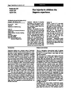
Deviate relay location and fuseplacements as well as the locations of multiple connectors see section ”component locations”. Relay location on the thirteenfold auxiliary relay panel, above relay panel:
10
Glow Plug Relay (180)
12
Power Supply (Terminal 30, B+) Relay (109)
Relay panel:
2
97--14163
Fuse colors 30 A - green 25 A - white 20 A - yellow 15 A - blue 10 A - red 7,5 A - brown 5 A - beige 3 A - violet
Edition 12/98 USA.5102.01.21
Load Reduction Relay (18)
Note: Number in parentheses indicates production control number stamped on relay housing.
No. 4/2
Golf/Jetta
Wiring diagram
5/31
9
J 59
3
21
2
4 7/30
S1/1
500
501
0,5 br 16,0 ro
6,0 ro
16,0 sw
1
0,5 br/ro
16,0 ro
T4/2 T4/1 T2e/2 T2e/1
A /+
110A
2,5 ro
6,0 ro
2
0,35 bl
110A
A32
50A
A98
50A
2,5 ro
D /30
39
0,5 br/ro
W 2
D+ 1
C C1
81 1
J59 -
6,0 ro
S177 S176 S162 S163
G
-
6,0 ro
61
B+
A C C1 D
20
154
0,5 bl
ws = white sw = black ro = red br = brown gn = green bl = blue gr = grey li = lilac ge = yellow
111
134
4
5
6,0 ro
2
3
4
5
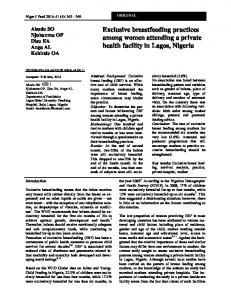
Battery Generator (GEN) Voltage Regulator (VR) Ignition/Starter Switch Load Reduction Relay Fuse -1- (30) in fuse bracket/battery Fuse -2- (30) in fuse bracket/battery Fuse -4- (30) in fuse bracket/battery Fuse -5- (30) in fuse bracket/battery Double Connector, near starter (vehicles without air conditioning) 4-Pin Connector, near starter (vehicles with air conditioning only)
S162 S163 S176 S177 T2e
-
T4
-
81
- Ground connection -1-, in instrument panel
6
7
8
9
10
11
12
13
14 97-23494
500
- Threaded connection -1- (30) on the relay plate
501
- Threaded connection -2- (30) on the relay plate
- Plus connection (30), in instrument panel wiring harness A98 - Plus connector -4- (30), in instrument panel wiring harness A32
wiring harness
Generator (GEN)
Edition 12/98 USA.5102.01.21
Golf/Jetta
No. 4/3
Wiring diagram
a
9
31
6,0 ro
1,0 bl
J 434 /2
2
2,5 sw
J52
9
2,5 ro/sw
A /+
5
7
S5
S7
5a
7a
7,5A 4
6
4,0 ro/ws
4,0 ro/ws
T6/3
T2a/1
3 0,5 br
1 0,5 li/ws
7 0,5 gn
0,35 sw/bl
2,5 ro/sw
30
1,0 sw/gn
T2a/2 A20
35,0 sw
10A
2,5 sw
2,5 sw
50
B
B163 0,35 sw/bl
1,0 sw/gn
104
141
Q6
M
b c
135 15
16
17
18
19
20
21
22
A - Battery B - Starter J52 - Glow Plug Relay, on the thirteenfold auxiliary relay panel, above relay panel J434 - Locking relay for starter (clutch pedal switch), on the thirteenfold auxiliary relay panel, above relay panel Q6 - Glow plugs (engine) S5 - Fuse 5 in fuse holder S7 - Fuse 7 in fuse holder T2a - Double Connector, in engine compartment, in wiring duct, left T6 - 6-Pin Connector, brown, in protective housing for connectors, in plenum chamber, left
Edition 12/98 USA.5102.01.21
23
24
25
26
27
ws = white sw = black ro = red br = brown gn = green bl = blue gr = grey li = lilac ge = yellow
28 97-23495
- Ground connection -2-, in instrument panel wiring harness A20 - Wire connection (15a), in instrument panel wiring harness B163 - Plus connector -1- (15) in wiring harness interior 135
Glow plug relay, starter, glow plugs (engine)
No. 4/4
Golf/Jetta
Wiring diagram
D /15
a 2,5 sw
A104
2,5 sw
A71
1,5 sw/li
1,5 sw/li
A2 1,5 bl
1,5 bl
43
1,0 bl
1,5 bl
21
91
2,5 bl
1,5 sw
32
10A
15A
S229
43a
32a
29a
1,0 bl/ge
2,5 ro
J317
29
S243 S232
T6/1
13
1,0 sw/li
J248
2/30
T80/47
10A
6/87
1,5 ro/li
2,5 bl
9/85
T80/33
0,5 bl/ge
T80/37
0,5 gn
T10h/
0,5 li/ws
T10e/ T10/3
8
8
B168
106 1,5 ro/li
1,5 ro/li
T6/4
ws = white sw = black ro = red br = brown gn = green bl = blue gr = grey li = lilac ge = yellow
T80/42
0,5 gn
0,5 li/ws
T10a/5
117
80
30
31
b c
29
32
33
D - Ignition/Starter Switch J248 - Diesel Direct Fuel Injection (DFI) Engine Control Module (ECM), in plenum chamber, center J317 - Power Supply (Terminal 30, B+) Relay, on the thirteenfold auxiliary relay panel, above relay panel S229 - Fuse 29 in fuse holder S232 - Fuse 32 in fuse holder S243 - Fuse 43 in fuse holder T6 - 6-Pin Connector, brown, in protective housing for connectors, in plenum chamber, left T10 - 10-Pin Connector, orange, in protective housing for connectors, in plenum chamber, left T10a - 10-Pin Connector, in engine compartment, in wiring duct, left
34
35
36
37
38
39
40
41
42 97-23496
T10e - 10-Pin Connector, black, in protective housing for connectors, in plenum chamber, left T10h - 10-Pin Connector, blue, in protective housing for connectors, in plenum chamber, left T80 - Connector, 80 point - Plus connection (15), in instrument panel wiring harness A71 - Connector (86), in instrument panel wiring harness A104 - Plus connector -2- (15), in instrument panel wiring harness B168 - Connection (86) in passenger compartment wiring harness A2
Diesel direct fuel injection (DFI) engine control module (ECM), power supply (terminal 30, B+) relay
Edition 12/98 USA.5102.01.21
Golf/Jetta
No. 4/5
Wiring diagram
T10/7
T10/8
0,5 gn
0,5 bl/ro ✱
✱
T80/16
J248
T80/48
T80/12
T80/25
0,5 gr/bl
1,0 br/bl
T80/8
0,5 gr/ws
T80/23 0,5 gr/ro
T80/11
0,5 ge/gn
T80/24
0,5 ws/bl
T80/43
0,5 ws/bl
T80/31
0,5 br/ws
T80/39 0,5 li/ro
T80/40
0,5 ge/sw
T80/13
0,5 gr/gn
T10h/ T10h/ T10h/ T10h/ T10h/ T10h/ T10h/ T10h/ 1
1,0 br/bl
1,0 br/bl
5
0,5 gr/bl
6
0,5 gr/ws
4
0,5 gr/ro
3
0,5 ge/gn
2
0,5 ws/bl
10
7
0,35 ws/bl
T6a/6 T6a/4 T6a/5 T6a/3 T6a/2 T6a/1 0,5 ge
0,5 gr
0,5 gn
0,5 br
0,5 rs
0,5 ws
159
3
4
2 í
F60
F8
G 71
G79
1
G 72
0,5 br/bl
220
43
44
45
46
47
48
49
50
51
52
53
54
55
ws = white sw = black ro = red br = brown gn = green bl = blue gr = grey li = lilac ge = yellow
56 97-23497
F8 F60 G71 G72 G79 J248
-
T6a T10 T10h T80 220
Kick Down Switch Closed Throttle Position (CTP) Switch Manifold Absolute Pressure (MAP) Sensor Intake Air Temperature (IAT) Sensor Throttle Position (TP) Sensor Diesel Direct Fuel Injection (DFI) Engine Control Module (ECM), in plenum chamber, center 6-Pin Connector, behind instrument panel, left 10-Pin Connector, orange, in protective housing for connectors, in plenum chamber, left 10-Pin Connector, blue, in protective housing for connectors, in plenum chamber, left Connector, 80 point
✱
- A/C connection
- Ground connection (sensor ground), in engine compartment wiring harness
Edition 12/98 USA.5102.01.21
Diesel direct fuel injection (DFI) engine control module (ECM), closed throttle position (CTP) switch, intake air temperature (IAT) sensor, manifold absolute pressure (MAP) sensor
No. 4/6
Golf/Jetta
Wiring diagram
J248 T80/54
T80/22
T80/70
0,5 bl/br
0,5 br/gn
0,5 br/ro
155
T80/41
T80/67 0,5 ws
0,5 bl/gn
T80/69
0,5 ge
T80/55
T80/62 0,5 gr
0,5 bl
T80/71
1,0 br/ge
0,35 li 0,5 sw
T10a/ T10d/ T10d/ 4
0,5 li
T2b T3 T10a T10d T80 -
3
2
8
0,5 br/ro
0,35 bl/gn
5
149
T3/3
T3/2
T3/1
0,5 sw
T2b/1 T2b/2
G2 G 28
G 80
0,5 br/ws
137
57
-
4
G62
ws = white sw = black ro = red br = brown gn = green bl = blue gr = grey li = lilac ge = yellow
G2 G28 G62 G80 J248
1
5
58
59
60
200
61
Engine Coolant Temperature (ECT) Sensor Engine Speed (RPM) Sensor Engine Coolant Temperature (ECT) Sensor Needle Lift Sensor Diesel Direct Fuel Injection (DFI) Engine Control Module (ECM), in plenum chamber, center Double Connector, in engine compartment, front 3-Pin Connector, in engine compartment, front 10-Pin Connector, in engine compartment, in wiring duct, left 10-Pin Connector, green, in protective housing for connectors, in plenum chamber, left Connector, 80 point
62
63
200
64
65
66
67
68
69
70 97-23498
- Ground connection (shielding), in engine compartment wiring harness
Diesel direct fuel injection (DFI) engine control module (ECM), engine speed (RPM) sensor, engine coolant temperature (ECT) sensor, needle lift sensor
Edition 12/98 USA.5102.01.21
Golf/Jetta
No. 4/7
Wiring diagram
J248 T80/52 1,0 br/bl
T80/4
T80/50
1,0 ro/gn
T80/76 0,5 br/bl
1,0 bl
T80/53
0,5 ge/bl
T80/56
0,5 li/sw
T80/57
0,5 gr/gn
T80/64
T80/66
0,5 ws/gn
1,0 br/ro
T80/59
1,0 br/ro
T80/80
1,0 br/ro
1,0 br/ro
T10f/
T10f/
4
5
4
T10f/
7
T10f/
1
T10f/
2
T10f/
3
F25
6
3 í 2
G 70
71
72
G81
G149
1,0 ge/sw
1,5 ro/li
93
31
73
74
75
76
77
78
ws = white sw = black ro = red br = brown gn = green bl = blue gr = grey li = lilac ge = yellow
N 146 T10f/5
79
80
81
82
83
84 97-23499
G70 G81 G149 J248 -
Mass Air Flow (MAF) Sensor Fuel Temperature Sensor Modulating Piston Displacement Sensor Diesel Direct Fuel Injection (DFI) Engine Control Module (ECM), in plenum chamber, center N146 - Quantity Adjuster T10f - 10-Pin Connector, in engine compartment, front T80 - Connector, 80 point F25
- Wire connection -1-, in Diesel Direct Fuel Injection (DFI) system wiring harness
Edition 12/98 USA.5102.01.21
Diesel direct fuel injection (DFI) engine control module (ECM), quantity adjuster, mass air flow (MAF) sensor, fuel temperature sensor, modulating piston displacement sensor
No. 4/8
Golf/Jetta
Wiring diagram
J248 T80/77 1,0 sw/ws
T80/79
T80/15
32
1,0 br/sw
0,5 br/ge
1,5 bl
T80/3
T80/29
1,0 li/gr
0,5 ro/bl
34
T10f/8
S234
T10f/9
10A 34a
1,0 ge/sw A100 1,0 ge/sw
1
N 109
ws = white sw = black ro = red br = brown gn = green bl = blue gr = grey li = lilac ge = yellow
N 108
T10a/
T10f/10
T6/5
6
2
1
2
1,0 ge/sw
N 75
73
1,0 ge/sw
2
N 239
N 18
1
2
1
1,0 ge/sw
1,0 ge/sw
1,5 sw/ge
1,0 ge/sw
93
94
E30 85
86
87
88
89
J248 - Diesel Direct Fuel Injection (DFI) Engine Control Module (ECM), in plenum chamber, center N18 - EGR Vacuum Regulator Solenoid Valve N75 - Wastegate Bypass Regulator Valve N108 - Cold Start Injector N109 - Fuel Cut-off Valve N239 - Change-over valve for intake manifold flap S234 - Fuse 34 in fuse holder T6 - 6-Pin Connector, brown, in protective housing for connectors, in plenum chamber, left T10a - 10-Pin Connector, in engine compartment, in wiring duct, left T10f - 10-Pin Connector, in engine compartment, front T80 - Connector, 80 point
90
91
A100
E30
92
95
96
97
98 97-23500
- Connector -2- (87), in instrument panel wiring harness - Connector (87a), in wiring harness engine
Diesel direct fuel injection (DFI) engine control module (ECM), cold start injector, fuel Edition 12/98 cut-off valve, wastegate bypass regulator valve, EGR vacuum regulator solenoid valve USA.5102.01.21
Golf/Jetta
No. 4/9
Wiring diagram
J248 T80/19
T80/35
0,5 sw/ws
0,5 ws
T10e/3
T80/10
T80/21
0,5 bl/gr
0,5 ro
26
T10e/ T10e/ 9
T80/46 0,5 ws/ro
T10e/2
1
T80/20
1,0 ro/sw
T80/9 10
0,5 ws/ge
6,0 ro
T10d/ T10e/ T10e/5 4
13
4
S13 10A
0,35 sw/ge
0,35 sw/ge
0,35 ws
T10s/ T10s/ 7
4
0,35 bl
0,35 sw/bl
1,0 ws/ro
0,35 ro/ge
1,0 ws/ge
13a
1,0 ro/br
T10s/ T10s/ T10s/ T10s/ 5
2
6
3
1
3
2 3201
F36 E45
E227
29 1,0 bl/ge
1
F47
1,0 bl/ge
2
F
1,0 bl/ge
4
1,0 ro/sw
129 1,0 bl/ge
A18 A52 99
E45 E227 F F36 F47 J248 S13 T10d T10e T10s T80 -
100
101
102
103
104
105
106
Cruise Control Switch✱✱ Cruise Control Push Button (SET)✱✱ Brake Light Switch Clutch Vacuum Vent Valve Switch Brake Vacuum Vent Valve Switch for cruise control/diesel Diesel Direct Fuel Injection (DFI) Engine Control Module (ECM), in plenum chamber, center Fuse 13 in fuse holder 10-Pin Connector, green, in protective housing for connectors, in plenum chamber, left 10-Pin Connector, black, in protective housing for connectors, in plenum chamber, left 10-Pin Connector, near steering column✱✱ Connector, 80 point
Edition 12/98 USA.5102.01.21
107
108
109
110
111
ws = white sw = black ro = red br = brown gn = green bl = blue gr = grey li = lilac ge = yellow
112 97-23501
A18
- Wire connection (54), in instrument panel
A52
wiring harness - Plus connection (30), in instrument panel wiring harness
✱✱
- Vehicles with cruise control only
Diesel direct fuel injection (DFI) engine control module (ECM), cruise control switch, brake vacuum vent valve switch, brake light switch, clutch vacuum vent valve switch
No. 4/10
Golf/Jetta
Wiring diagram
d
A27 0,35 bl/ws
T10/6 0,5 bl/ws
J248 T80/1 2,5 br/ro
T80/27 2,5 br/ro
T80/28 1,5 ro/li
T80/2
1,5 ro/li
D74
1,5 ro/li
T80/45 K
0,5 gr/ws
T80/18
0,5 gn/ws
T80/51
T80/75
0,5 or/br
0,5 or/sw
T10/1 T10/2 T2c/1 0,35 gr/ws
0,35 gn/ws
T80/68
J
104 T25/10
0,35 or/br
0,5 or/br
J
104 T25/11
T2c/2
0,35 or/sw
0,5 or/sw
* 30
160
T10d/3
150
T10d/2
0,5 ws
0,5 sw A122
ws = white sw = black ro = red br = brown gn = green bl = blue gr = grey li = lilac ge = yellow or = orange
A121
2,5 br/ro 156 113
156 114
608 115
116
117
J104 - ABS Control Module (w/EDL), in engine compartment, left J248 - Diesel Direct Fuel Injection (DFI) Engine Control Module (ECM), in plenum chamber, center T2c - Double Connector, in engine compartment, in wiring duct, left T10 - 10-Pin Connector, orange, in protective housing for connectors, in plenum chamber, left T10d - 10-Pin Connector, green, in protective housing for connectors, in plenum chamber, left T25 - 25-Pin Connector, on ABS Control Module (w/EDL) T80 - Connector, 80 point
118
119
120
121
122
123
124
125
126 97-23502
- Ground connection, in Diesel Direct Fuel Injection (DFI) wiring harness A27 - Wire Connection (vehicle speed signal), in instrument panel wiring harness A121 - Connection (high bus), in instrument panel wiring harness A122 - Connection (low bus), in instrument panel wiring harness D74 - Wire connection (86), in engine compartment wiring harness 156
*
- Vehicles with Multi-Function Indicator (MFI) only
608 - Ground Connection (in center plenum chamber)
Diesel direct fuel injection (DFI) engine control module (ECM)
Edition 02/99 USA.5102.02.21
Golf/Jetta
No. 4/11
Wiring diagram
d
d e 0,35 gn/br
112
D50
1,0 bl/ge
T10/9
4,0 ro
4,0 ro
T6/6
0,5 gn/br
J248
T80/6
2/30
13/86
0,5 sw/br
T80/17
0,35 li/sw
8
0,35 br/ws
J 360 6/85
0,5 sw/bl
8/87
15/85
2,5 sw
0,35 li/ro
11/30
J 359 T80/34
6,0 ro
1,0 bl/ge 4/86
f g h
165
17/87 4,0 sw
166
✱
✱
0,35 br/ws
0,35 br/ws
1,0 br/ws
0,5 br/ws
269 0,5 br/ws D98 2,5 sw
2,5 sw
T10a/9 0,5 br/ws
1
G 32
G
Q7
2
127
128
129
130
131
132
133
134
G - Fuel Level Sensor G32 - Engine Coolant Level (ECL) Sensor J248 - Diesel Direct Fuel Injection (DFI) Engine Control Module (ECM), in plenum chamber, center J359 - Relay for preheating coolant, low heat output, in protective housing, in engine compartment, left, production control number (53) J360 - Relay for preheating coolant, high heat output, in protective housing, in engine compartment, left, production control number (53) Q7 - Glow plugs (coolant) T6 - 6-Pin Connector, brown, in protective housing for connectors, in plenum chamber, left T10 - 10-Pin Connector, orange, in protective housing for connectors, in plenum chamber, left
Edition 12/98 USA.5102.01.21
1
135
136
137
ws = white sw = black ro = red br = brown gn = green bl = blue gr = grey li = lilac ge = yellow
2
60
138
139
140 97-23503
T10a - 10-Pin Connector, in engine compartment, in wiring duct, left T80 - Connector, 80 point - Ground connection (sensor ground) -1-, in instrument panel wiring harness D50 - Plus connection (30), in engine compartment wiring harness D98 - Wire connection (glow plugs), in engine compartment wiring harness 269
✱
- Vehicles with Multi-Function Indicator (MFI) only
Diesel direct fuel Injection (DFI) engine control module (ECM), fuel level sensor, glow plugs (coolant), engine coolant level (ECL) sensor
No. 4/12
Golf/Jetta
Wiring diagram
d
d
e
e
f
f
g h
0,35 gn/sw
0,35 gn
0,35 gn
62
119
4
0,35 bl/gn
0,35 gn/ws
0,35 li/ro
0,35 br/ws
0,35 bl
* 28
T32/10
T32/28
1,0 sw/gn
T32/13
T32a/ 32
T32/22
T32/7
T32/12
K29
K2
J285 T10a/ T10a/ T10a/ 10
2
1,0 sw/ws
0,5 ws/bl
1
2
K2 K3 K28 K29 T10a T32 T32a -
2,5 br
0,5 gn/sw
H3
K3
K 28
3
G22
608 141
-
1,0 br
F1
ws = white sw = black ro = red br = brown gn = green bl = blue gr = grey li = lilac ge = yellow
F1 G22 H3 J285
T10a/1
7
142
143
144
145
Oil Pressure Switch Speedometer Vehicle Speed Sensor (VSS) Warning Buzzer Control module with indicator unit in instrument panel insert Generator (GEN) Warning Light Oil Pressure Warning Light Engine Coolant Level/Temperature (ECL/ECT) Warning Light Glow Plug Indicator Light 10-Pin Connector, in engine compartment, in wiring duct, left 32-Pin Connector, blue 32-Pin Connector, green
146
147
148
149
150
151
152
153
154 97-23504
608 - Ground Connection (in center plenum chamber)
*
- Vehicles with Multi-Function Indicator (MFI) only
Instrument cluster, oil pressure switch, speedometer vehicle speed sensor, engine coolant level/temperature (ECL/ECT) warning light, glow plug indicator light
Edition 02/99 USA.5102.02.21
Golf/Jetta
No. 4/13
Wiring diagram
d
A27
118
e
0,5 gr/ws
T16/7 K 0,5 gr/ws
f
0,35 li/sw
0,35 gn/br
0,35 bl/ws
60
51
0,35 li
0,35 ws/bl
T32/8
T32/5
G3
T32/11
0,35 bl/gn
A76
T32/3
0,35 bl
0,35 bl/gr
0,35 gr/ws
T32/32
K T32/25
T32a/ 24
T32a/ 23
T32a/25
✱
✱
✱
T6e/4
T6e/2
T6e/1
T6e/3
E 86
G1 K83
E 109
J285
0,35 br/ws
K105
✱
J119
G21
137
139
✱
T32a/26 0,35 br/ge
0,35 br/ws
ws = white sw = black ro = red br = brown gn = green bl = blue gr = grey li = lilac ge = yellow
2 ϑ
✱
G17 1
155
E86 E109 G1 G3 G17 G21 J119 J285
-
K83 K105 T6e T16
-
T32 T32a -
156
157
158
159
160
161
162
Multi-Function Indicator Mode Select Switch Multi-Function Indicator Memory Switch Fuel gauge Engine Coolant Temperature (ECT) Gauge Outside Air Temperature Sensor Speedometer Multi-function Indicator (MFI) Control module with indicator unit in instrument panel insert Malfunction Indicator Lamp (MIL) Low Fuel Level Warning Light 6-Pin Connector Data Link Connector (DLC), below instrument panel, center 32-Pin Connector, blue 32-Pin Connector, green
Edition 12/98 USA.5102.01.21
163
164
A27 A76
✱
165
166
167
168 97-23505
- Wire Connection (vehicle speed signal), in instrument panel wiring harness - Connector (K-diagnosis wire), in instrument panel wiring harness - Vehicles with Multi-Function Indicator (MFI) only
Instrument cluster, multi-function indicator (MFI), engine coolant temperature (ECT) gauge, fuel gauge, speedometer, malfunction indicator lamp (MIL), outside air temperature sensor