GPU-Accelerated Parallel Finite-Difference Time-Domain Method for Electromagnetic Waves Propagation in Unmagnetized Plasma Media Xi-min Wang, Lang-lang Xiong, Song Liu, Zhi-yun Peng, and Shuang-ying Zhong
Abstract—The finite-difference time-domain (FDTD) method has been commonly utilized in the numerical solution of electromagnetic (EM) waves propagation through the plasma media. However, the FDTD method may bring about a significant increment in additional run-times consuming for computationally large and complicated EM problems. Graphics Processing Unit (GPU) computing based on Compute Unified Device Architecture (CUDA) has grown in response to increased concern for reduction of run-times. We represent the CUDA-based FDTD method with the Runge-Kutta exponential time differencing scheme (RKETD) for the unmagnetized plasma implemented on GPU. In the paper, we derive the RKETD-FDTD formulation for the unmagnetized plasma comprehensively, and describe the detailed flowchart of CUDA-implemented RKETD-FDTD method on GPU. The accuracy and acceleration performance of the posed CUDA-based RKETD-FDTD method implemented on GPU are substantiated by the numerical experiment that simulates the EM waves traveling through the unmagnetized plasma slab, compared with merely CPU-based RKETD-FDTD method. The accuracy is validated by calculating the reflection and transmission coefficients for one-dimensional unmagnetized plasma slab. Comparison between the elapsed times of two methods proves that the GPU-based RKETD-FDTD method can acquire better application acceleration performance with sufficient accuracy. Index Terms—Parallel FDTD, Unmagnetized plasma, Compute unified device architecture (CUDA), Graphic processing unit (GPU)
I. INTRODUCTION Since the finite-difference time-domain (FDTD) method was initially delivered to numerically resolve the Maxwell’s equations by Yee in 1966 [1], it has been widely used in the numerical solution of electromagnetics (EMs) problems. The FDTD method has obvious advantages over many other numerical methods as it updates naturally the field values at every separate cell in discrete time steps by leap-frog integrations without complex computations [2]. Over the past decade, the FDTD numerical modeling approach has led to applications to diverse difficulties, involving modeling of objects ranging from aerospace and biological systems to geometric shapes, analysis and design of complicated microwave circuits and fast time-varying systems as well as various other engineering applications [3]. Plentiful numerical schemes related to FDTD formulations used to simulate the EM waves propagation in the dispersive media are addressed, including the recursive convolution (RC) method [4,5], frequency-dependent Z transform method [6,7], direct integration (DI) method [8, 9], JE convolution (JEC) method [10], the auxiliary differential equation (ADE) method [11],
Manuscript received; This work is supported by National Nature Science foundation of China (No. 61261006 & 11563006 &1116501), the State Key Laboratory of Millimeter Waves Open Research Program (No. K201605), and it was also supported by the Natural Science Foundation of Jiangxi Province (No. 20151BAB202024). Xi-min Wang is with Electrical Engineering, Nanchang University, Nanchang Jiangxi 330031, China. Lang-lang Xiong is with School of Sciences, Nanchang University, Nanchang Jiangxi 330031, China. Song Liu is with School of Sciences, Nanchang University, Nanchang Jiangxi 330031, China; and State Key Laboratory of Millimeter Waves, Nanjing Jiangsu 210016, China. (Email:
[email protected]) Zhi-yun Peng is with Electrical Engineering, Nanchang University, Nanchang Jiangxi 330031, China. Shuangying Zhong is with School of Sciences, Nanchang University, Nanchang Jiangxi 330031, China; (Email:
[email protected]) (corresponding author Email:
[email protected]).
piecewise linear recursive convolution (PLRC) method [12], piecewise linear current density recursive convolution (PLCDRC) method [13], Runge-Kutta exponential time differencing (RKETD) [14]. Simulation of EM waves propagating through plasma media is a unique and fascinating application built on FDTD formulations for dispersive media, where the appearing nonlinear phenomena that are not totally understood can be explicitly refined by numerical simulation.
Furthermore, aforementioned various FDTD scheme for
CUDA. Section Ⅳ designs a numerical simulation that is
dispersive media can be applied to the plasmas.
carried out to prove the accuracy and efficiency of the
Although the FDTD schemes above are well-suited to
GPU-based RKETD-FDTD method for unmagnetized plasma.
numerical simulation, the original FDTD method can bring II. RKETD-FDTD FORMULATION
about a significant increment in additional run-times consuming for computationally large and complicated EM issues. However, FDTD method is naturally a massively
The famous Maxwell’s equations in time domain for the unmagnetized plasma are provided by
parallel algorithm, thus it can benefit a lot from most advances in parallel computing techniques to acquire considerable decrease in time spending. Graphics Processing Units (GPUs) have been industrialized rapidly in recent years, which are considered as the most popular hardware accelerator in parallel
Ñ´ H = e ¶E + J 0 ¶t
(1)
Ñ´ E = -µ ¶H 0 ¶t
(2)
dJ +n J = e w 2 E 0 p dt
(3)
computation to settle massively parallel computations with
where, H is the magnetic intensity, E is the electric field, J
better application acceleration performance obtained.
is the polarization current density, n is the electron collision
Since the Compute Unified Device Architecture (CUDA) was first introduced by NVIDIA as a parallel computing
e 0 and µ0 are the
frequency, w p is plasma frequency,
platform and software programming model, GPUs have turned
permittivity and permeability of free space, respectively.
out to be much more formidable and generalized for developers
Considering one-dimensional equations, the one-dimensional
to be utilized to tackle general-purpose parallel computations
component of the equations can be written as
with high performance. Previous researches about diverse FDTD schemes based on CUDA-enabled GPU have been undertaken over the past decade [15-20]. What’s more, FDTD method carried out on multi-GPU clusters has triggered great interest to further accelerate large-scale computations with improved speedup performance [21-24]. This paper presents a GPU-based RKETD-FDTD method with CUDA for the unmagnetized plasma media to acquire better acceleration performance, compared with merely CPU-based RKETD-FDTD method. Numerical simulation of the GPU-based RKETD-FDTD method for the unmagnetized plasma media is undertaken both on CPU and GPU respectively. The reflection and transmission coefficients through an unmagnetized plasma layer in one dimension are calculated to validate the accuracy of the method. Speedup ratios are computed to confirm the speedup performance of the method. This paper is arranged as follows. In Section Ⅱ, we describe the Maxwell equations for the unmagnetized plasma and derives the FDTD formulation with RKETD numerical scheme. Section Ⅲ illustrates the CUDA programming model and implementation of GPU-based RKETD-FDTD method with
-
¶H y ¶Ex =e + Jx 0 ¶t ¶z
(4)
¶H y ¶Ex = -µ 0 ¶t ¶z
(5)
dJ x +n J x = e w 2p Ex 0 dt
(6)
To derive FDTD formulation with RKETD scheme for the unmagnetized plasma, equation (6) is multiplied by the integrating factor
enDt and then integrated from tn to tn +1 ,
letting Dt = tn+1 - tn and t = tn + t . The result is given by Dt
J xn+1 = e -nDt J xn + e -nDt ò ent F (tn + t )dt 0
(7)
Where, F (tn + t ) = e 0w p2 Ex (tn + t ) . To derive the second-order RKETD method, first define K = e -nDt J xn +
F (tn , J x )(1 - e -nDt ) n
(8)
Next the approximation is taken to give F (tn + t ) = F (tn , J x ) +
t [ F (tn + Dt, K ) - F (tn , J x )] + o ( (Dt )2 ) Dt
Combining equation (7) and (9) yields Dt
J xn+1 = e -nDt J xn + F (tn , J x )e -nDt ò ent dt 0
(9)
+ [ F (tn + Dt , K ) - F (tn , J x ) ]
The x component of J at
e-nDt Dt
ò
Dt
0
(10)
t ent dt
n + 1 time step can be arranged as
J xn+1 = e-nDt J xn + +
1- e
n
-nDt
compute capability of GPU hardware more efficiently. CUDA programs involve codes running on two different platforms concurrently: host codes on CPU and device codes on GPU. There are distinct hardware differences between CPU
e 0w p2 Exn
e -nDt - 1 + nDt e 0w p2 ( Exn+1 - Exn ) n 2 Dt
and GPU, whose separate memory named host and device (11)
memory respectively. Hence, the host is the location where the
So equation (11) can be used to update the x component of the
sequential parts of CUDA programs are executed, and the
polarization current density J by utilizing the x component of
device is where the intensively data-parallel parts are executed
the electric field E at both n and n + 1 time steps.
in the form of kernels. Kernels are critical and unique to CUDA
The discretization of equation (4) follows the Yee grid and
programs. A kernel is always executed on the device after being
leapfrog-style algorithm, which is taken to give
invoked on the host, explicitly specified as the calculation and
Exn+1 (k ) = Exn (k ) -
memory manipulation for solely a single thread.
1 1 n+ Dt é n+ 2 1 1 ù 2 ê H y (k + ) - H y (k - ) ú 2 2 û
e 0 Dz ë
-
Dt é J xn+1 (k ) + J xn (k ) ùû 2e 0 ë
As soon as a kernel is launched on the host, a large number of (12)
1
given by 1
each
performing
structure, that is, CUDA organizes blocks and grids in three (13)
formulation for vacuum, and the update equation of H is
1
generated,
and group blocks into grids. In the light of the hierarchy
The discretization of equation (5) strongly resembles the FDTD
n+ n1 1 Dt H y 2 (k + ) = H y 2 (k + ) [ Exn (k + 1) - Exn (k )] 2 2 µ0 Dx
concurrently
two-level thread hierarchy, which divides threads into blocks
w p2 Dt -nDt (e - 1) Dt n+1 2n Ex (k ) = (1 + ) Exn (k ) (1 + e-nDt ) J xn (k ) w p2 -nDt 2e 0 1 + 2 (e - 1 + nDt ) 2n 1
are
calculations of the same pattern in parallel. CUDA reveals a
Substituting equation (11) into equation (12) gives
n+ n+ Dt 1 1 [ H 2 (k + ) - H y 2 (k - )] e 0 Dz y 2 2
threads
(14)
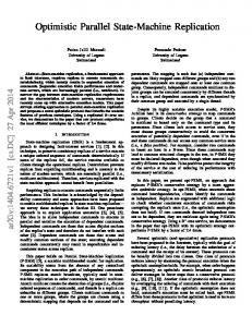
dimension, programmers can utilize the hardware resources for optimization more straightforwardly. Figure 1 shows an illustrative instance of a thread hierarchy structure with a two-dimensional grid containing two-dimensional blocks. Effective thread configuration becomes essential to CUDA programming for the obtainment of better application acceleration performance. Device(GPU)
Host (CPU)
III. CUDA IMPLEMENTATION Grid 0
A. CUDA Programming Model Parallel programming techniques are compatible with computations that could be operated on concurrence of
Kernel 0
Block (0,0)
Block (1,0)
Block (2,0)
Block (0,1)
Block (1,1)
Block (2,1)
Kernel 1
plentiful data elements in parallel, with the intention of acquiring better acceleration performance by mapping data
Block(1,1)
elements to numerous threads concurrently on GPU. During the
Thread (0,0)
Thread (1,0)
Thread (2,0)
Thread (3,0)
Thread (4,0)
process, a bridge is built by CUDA programming model
Thread (0,1)
Thread (1,1)
Thread (2,1)
Thread (3,1)
Thread (4,1)
between applications and their implementations on NVIDIA
Thread (0,2)
Thread (1,2)
Thread (2,2)
Thread (3,2)
Thread (4,2)
GPU. Moreover, CUDA programming model abstracts the computer
architecture
to
offer
programmers
effective
Figure 1 (color online) a thread hierarchy structure with a two-dimensional grid containing two-dimensional blocks
perspectives to manipulate memory and organize threads on
Moreover, CUDA programming model represents the
CUDA-supported GPU, so that they are able to harness the
complete memory hierarchy clearly to access and manage
memory
for
optimal
performance.
Several
types
of
intensity and E-update-kernel to update the electric field. The
programmable device memory are presented, such as local
two kernels with dotted line border are launched sequentially
memory, global memory, shared memory, constant memory
and executed in parallel on GPU. Shared memory is often used
and texture memory. Figure 2 illustrates the GPU memory
to efficiently implement the FDTD update kernels for optimum,
hierarchy exposed in CUDA memory model. These memory
compared to merely global memory utilized. The execution
spaces slightly differ in the lifetimes, scopes and caching
configuration for each kernel is governed by the complete
behaviors. Local memory is allocated for threads in a kernel.
domain and allocated shared memory, for the reason that the
Shared memory is shared by all threads of the same block,
calculating of a Yee’s cell is mapped to a thread on the device.
which can be configured by threads of a block with lifetime as
START
block. Global memory accessible by all threads is expected to be much slower than shared memory. Constant and texture memory accessible by all threads are read-only memory, optimized for diverse memory practices. Global, constant and texture memory are continuing with same lifetime as an application [25].
Organize threads for E-update-kernel
Initialize fields and PML parameters
Allocate shared memory for H-fields
Allocate GPU (global) memory
(Device) Grid
Update E-fields with different update schemes in plasma media and free space respectively
Copy data from CPU memory to GPU memory
Block (1, 1)
Update J-fields in plasma media
Shared Memory
Host
Allocate CPU (host) memory
Invoke kernels
Registers
Registers
Thread (0, 0)
Thread (1, 0)
Local Memory
Local Memory
?
Copy data back from GPU memory to CPU memory
Global Memory
Update H-fields in computational domain
Deallocate GPU memory and CPU memory
Texture Memory
Figure 2 (color online) GPU memory hierarchy in CUDA memory model
END
Figure 3 Flowchart of GPU-based FDTD method with CUDA
Compared with RKETD-FDTD method on CPU, we
IV. NUMERICAL SIMULATION
illustrate the flowchart of GPU-based RKETD-FDTD method displayed in Figure 3. The host code is implemented to
Allocate shared memory for E-fields
Retrieve results
Constant Memory
B. CUDA-implemented RKETD-FDTD method
Organize threads for H-update-kernel
A. Simulation environment
complete fields and parameters initialization, device memory
As briefly stated before, it’s theoretically predicted that the
allocation and release, and data transfer between host and
GPU-based RKETD-FDTD method can acquire better
device. To efficiently implement GPU-based RKETD-FDTD
acceleration performance compared with the corresponding
method with CUDA, device codes are considered to be divided
simply
into two kernels: H-update-kernel to update the magnetic
RKETD-FDTD method is utilized to simulate EM waves
CPU-based
RKETD-FDTD
method,
when
traveling
through
the
unmagnetized
plasma
media.
The source wave exploited in numerical experimentation is the
Nevertheless, the application acceleration performance of the
Gaussian-derivative pulsed plane wave, which is given in time
GPU-based RKETD-FDTD method isn’t always as satisfying
domain by
as estimated in practical applications, which frequently changes
æ (t - 5t ) 2 ö Ei (t ) = (t - 5t ) exp ç ÷, 2t 2 ø è
with problem complexities, GPU hardware properties and
(15)
here, t = 15Dt .
programmers’ skills. To evaluate the acceleration performance of GPU-based
The execution configurations of the two kernels are arranged
RKETD-FDTD method, we prefer CUDA as the parallel
both as 16 blocks in each grid and 256 threads in each block in
programming platform to employ the acceleration of the
case of the computational domain, with CUDA programming
GPU-based RKETD-FDTD method for the unmagnetized
model constructed.
plasma media. The numerical experiment is performed on the
To validate the accuracy of the GPU-based RKETD-FDTD
laptop provided with CUDA-supported NVIDIA GPU. The
method with CUDA compared with the RKETD-FDTD method
CPU of the laptop is Intel Core i5 3230M, and GPU NVIDIA
merely CPU-based, reflection and transmission coefficients are
GeForce GT 650M. GeForce GT 650 is a low-end product
analyzed with the Fast Fourier Transform (FFT). Figure 4 and 5
based on graphics processor of NVIDIA Kepler architecture,
clarify
the
magnitudes
developed for desktop applications. Some key specifications of
transmission
coefficient
GT650 are tabulated in Table 1. The development environment
CUDA-implemented RKETD-FDTD method on GPU and
is Microsoft Visual Studio 2013 (Community Edition) with
RKETD-FDTD method on CPU with those of the analytical
CUDA toolkit 7.5 assembled, Windows 10 as operating system.
solution. From Figure 4 and 5, it’s taken to show that the
Specification
GeForce GT 650M
Chip
GK107
CUDA cores
384
Processor clock
835MHz
Memory clock
900MHz
Memory size
4096MB
B. Numerical Results To exhibit the simulation of abovementioned RKETD-FDTD formulation for the unmagnetized plasma media, we choose appropriate parameters that are listed as follows. The entire computational domain is 4096Dz in z axis, where Dz is selected to be Dz = 75 µ m as size of a cell. A single time step is taken to be Dt = 125ns . The unmagnetized plasma slab with the thickness of 9cm occupies the middle 1200 cells, the PML absorbing boundary conditions [26] are implemented at both ends of 5 cells to avoid undesired reflections, and the rest space is vacuum. The key parameters of unmagnetized plasma are 9 wp = 2p ´ 28.7 ´ 10 rad / s and n = 20GHz .
CUDA-implemented
reflection
computed
RKETD-FDTD
coefficient
and
respectively
by
method
achieves
agreement in reasonable accuracy with the RKETD-FDTD method and the analytical solution at higher frequency. 0
Reflection coefficient magnitude (dB)
Table 1 Specifications of NVIDIA 650M
of
-20
-40
-60
-80
FDTD on CPU FDTD on GPU Analytical solution 0
10
20
30
40
50
60
70
80
90
100
Frequency (GHz)
Figure 4 (color online) Reflection coefficient magnitude versus frequency
60 Free Space
Plasma Slab
Free Space
40 -20
20 FDTD on CPU FDTD on GPU Analytical solution
Time Step = 3000
Ex(V/m)
Transmission coefficient magnitude (dB)
0
-40
0
-20
-40 -60
0
10
20
30
40
50
60
70
80
90
FDTD on CPU FDTD on GPU
100
-60
Frequency (GHz)
0
1000
Figure 5 (color online) Transmission coefficient magnitude versus frequency
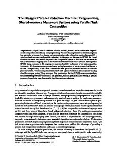
Figure 6 through 9 show the electric field magnitude at each FDTD cell after various time steps to demonstrate a plasma
slab
with
n = 50GHz
3000
4000
Figure 7 (color online) Electric field magnitude versus Yee’s cells after 3000 time steps
Gaussian-derivative pulsed plane wave propagating through an unmagnetized
2000
FDTD Cells
60
Free Space
and
Plasma Slab
Free Space
40
9 wp = 2p ´ 50 ´ 10 rad / s . Some sharp corners occur at the
boundary conditions must be satisfied.
Ex(V/m)
border of the plasma slab and vacuum, for the reason that the
20
Time Step = 4000 0
-20
-40
60 Free Space
Plasma Slab
-60
Free Space
FDTD on CPU FDTD on GPU 0
1000
3000
4000
Figure 8 (color online) Electric field magnitude versus Yee’s cells after 4000
20
Time Steps = 2000
Ex(V/m)
2000
FDTD Cells
40
time steps
0 60
-20
Free Space
Plasma Slab
Free Space
40
-40
0
1000
2000
3000
4000
FDTD Cells
20
Ex(V/m)
-60
FDTD on CPU FDTD on GPU
Time Step = 5500 0
-20
Figure 6 (color online) Electric field magnitude versus Yee’s cells after 2000
-40
FDTD on CPU FDTD on GPU
time steps -60
0
1000
2000
3000
4000
FDTD Cells
Figure 9 (color online) Electric field magnitude versus Yee’s cells after 5500 time steps
Due to the fact that the application speedup performance may vary with GPU device properties and developers’ programming levels, speedup ratio is calculated to evaluate the practical application speedup performance, which is termed as the ratio
between the elapsed times of FDTD computation part only on
CPU. Numerical experiments of these two methods have been
CPU and on GPU in the simulation. Table 2 presents the
done respectively on NVIDIA GPU and on CPU. The accuracy
elapsed time of FDTD computation part only on CPU and on
and
GPU and corresponding speedup ratio at diverse time steps
GPU-implemented RKETD-FDTD method were assessed by
with Yee’s cells unchanged.
the numerical simulation of the EM waves traveling through the
Table 2 Speedup ratio at diverse time steps in the simulation
unmagnetized plasma slab, compared with simply CPU-based
acceleration
performance
of
the
represented
CPU Times
GPU Times
Speedup
RKETD-FDTD method. The accuracy was verified by
(s)
(s)
Ratios
calculating the reflection and transmission coefficients for
1000
0.258
0.058
4.45
one-dimensional unmagnetized plasma slab. The comparison
3000
0.770
0.263
2.93
between the elapsed times of two methods proved that the
5000
1.292
0.481
2.69
posed GPU-based RKETD-FDTD method implemented with
7000
1.832
0.689
2.66
CUDA can acquire decent acceleration with sufficient accuracy.
9000
2.321
0.887
2.62
The further research will be predicted to obtain more
10000
2.579
1.014
2.54
satisfactory acceleration performance while the numerical
15000
3.906
1.513
2.58
results of GPU-based RKETD-FDTD method are generalized
20000
5.063
2.048
2.47
to two-dimensional and even three-dimensional conditions for
Time Steps
practical
applications.
Besides,
more
sophisticated
The speedup ratio is slowly decreasing with time step
CUDA-supported GPUs specialized in scientific computation
increasing. The speedup ratios calculated in Table 2 validate
such as Tesla can be utilized to acquire better acceleration
the speedup performance of the GPU-based RKETD-FDTD
performance.
method with respect to that only on CPU, by numerically simulating EM waves traveling through the unmagnetized plasma slab in one direction. We can easily make further improvement in speedup performance for practical applications when the numerical
REFERENCES [1] Yee, Kane S. "Numerical solution of initial boundary value problems involving Maxwell’s equations in isotropic media." IEEE Trans. Antennas Propag., vol. 14, no. 3, pp. 302-307, 1966. [2] Taflove, Allen, and Susan C. Hagness. Computational electrodynamics. Artech house, 2005.
results of GPU-based RKETD-FDTD method are generalized
[3] Taflove, Allen. "Review of the formulation and applications of the
to the two- dimensional and even three-dimensional conditions
finite-difference time-domain method for numerical modeling of
to get full use of the GPU computing resources, compared with
electromagnetic wave interactions with arbitrary structures." Wave Motion,
the one dimensional condition just to confirm the speedup performance. Besides, NVIDIA GeForce GT 650M used in the simulation is one product of the low-end GPUs that are not developed for scientific computation. More sophisticated CUDA-supported GPU such as Tesla can be upgraded to obtain better speedup performance.
vol. 10, no. 6, pp. 547-582, 1988. [4] Luebbers, Raymond J., and Forrest Hunsberger. "FDTD for N th-order dispersive media." IEEE Transactions on Antennas and Propagation, vol.40, no. 11, pp. 1297-1301, 1992. [5] Siushansian, Riaz, and Joe LoVetri. "A comparison of numerical techniques for modeling electromagnetic dispersive media." IEEE Microwave and Guided Wave Letters, vol. 5, no. 12, pp. 426-428, 1995. [6] Sullivan, Dennis M. "Frequency-dependent FDTD methods using Z transforms." IEEE Transactions on Antennas and Propagation, vol. 40, no.
V. CONCLUSION AND PERSPECTIVES In this letter, we presented a CUDA-based RKETD-FDTD method for the unmagnetized plasma implemented on GPU to acquire better acceleration performance, when compared with the previous RKETD-FDTD method simply implemented on
10, pp. 1223-1230, 1992. [7] Pereda, José, Ángel Vegas, and Andrés Prieto. "FDTD modeling of wave propagation in dispersive media by using the Mobius transformation technique." IEEE Transactions on Microwave Theory and Techniques, vol. 50, no. 7, pp. 1689-1695, 2002.
[8] Young, Jeffrey L. "Propagation in linear dispersive media: Finite difference
[22]Shams R, Sadeghi P. “On optimization of finite-difference time-domain
time-domain methodologies." IEEE Transactions on Antennas and
(FDTD) computation on heterogeneous and GPU clusters”. Journal of
Propagation, vol. 43, no. 4, pp. 422-426, 1995.
Parallel and Distributed Computing, vol. 71, no. 4, pp. 584-593, 2011.
[9] Young, Jeffrey L. "A higher order FDTD method for EM propagation in a
[23]Kim K H, Park Q H. “Overlapping computation and communication of
collisionless cold plasma." IEEE Transactions on Antennas and
three-dimensional FDTD on a GPU cluster”. Computer Physics
Propagation, vol. 44, no. 9, pp. 1283-1289, 1996.
Communications, vol. 183, no. 11, pp. 2364-2369, 2012.
[10] Chen, Qing, Makoto Katsurai, and Paul H. Aoyagi. "An FDTD
[24]Nagaoka, T., and Watanabe S. Accelerating “three-dimensional FDTD
formulation for dispersive media using a current density." IEEE
calculations on GPU clusters for electromagnetic field simulation”.
Transactions on Antennas and Propagation, vol. 46, no. 11, pp. 1739-1746,
International Conference of the IEEE Engineering in Medicine and
1998. [11] Takayama, Yoshihisa, and Werner Klaus. "Reinterpretation of the auxiliary differential equation method for FDTD." IEEE Microwave and Wireless Components Letters, vol. 12, no. 3, pp. 102-104, 2002. [12] Kelley, David F., and Raymond J. Luebbers. "Piecewise linear recursive convolution for dispersive media using FDTD." IEEE Transactions on Antennas and Propagation, vol. 44, no. 6, pp. 792-797, 1996. [13] Shaobin Liu, Naichang Yuan, and Jinjun Mo. "A novel FDTD formulation for dispersive media." IEEE Microwave and Wireless Components Letters, vol. 13, no. 5, pp. 187-189, 2003. [14] Song Liu, Shuangying Zhong, and Shaobin Liu. "Finite-difference time-domain algorithm for dispersive media based on Runge-Kutta exponential time differencing method." International Journal of Infrared and Millimeter Waves, vol. 29, no. 3, pp. 323-328, 2008. [15] Wang X, Liu S, Li X, Zhong S.Y. "GPU-accelerated finite-difference time-domain method for dielectric media based on CUDA," International Journal of RF and Microwave Computer-Aided Engineering, to be published. [16] Stefanski, Tomasz P., and Timothy D. Drysdale. "Acceleration of the 3D ADI-FDTD method using Graphics Processor Units." In Microwave Symposium Digest, 2009. MTT'09. IEEE MTT-S International. 2009. [17] De Donno, Danilo, Alessandra Esposito, Luciano Tarricone, and Luca Catarinucci. "Introduction to GPU computing and CUDA programming: A case study on FDTD." IEEE Antennas and Propagation Magazine, vol. 52, no. 3, pp. 116-122, 2010. [18] Zunoubi, Mohammad Reza, Jason Payne, and William P. Roach. "CUDA Implementation of TEz-FDTD Solution of Maxwell's Equations in Dispersive Media." IEEE Antennas and Wireless Propagation Letters, no. 9, pp. 756-759, 2010. [19] Lee, Kim Huat, Iftikhar Ahmed, Rick Siow Mong Goh, Eng Huat Khoo, Er Ping Li, and Terence Gih Guang Hung. "Implementation of the FDTD method based on Lorentz-Drude dispersive model on GPU for plasmonics applications." Progress In Electromagnetics Research vol. 116, pp. 441-456, 2011. [20] Livesey, Matthew, James Francis Stack, Fumie Costen, Takeshi Nanri, Norimasa Nakashima, and Seiji Fujino. "Development of a CUDA Implementation of the 3 D FDTD Method." IEEE Antennas & Propagation Magazine, vol. 54, no. 5, pp. 186-195, 2012. [21]Ong C, Weldon M, Cyca D, Okoniewski M. “Acceleration of large-scale FDTD simulations on high performance GPU clusters”. 2009 Antennas & Propagation Society International Symposium, 2009, 1-4.
Biology Society, 2012: 5691-4. [25]Cheng, John, Max Grossman, and Ty McKercher. “Professional CUDA C Programming”. John Wiley & Sons, 2014. [26] J.-P. Berenger, “A perfectly matched layer for the absorption of electromagnetic waves,” J. Comput. Phys., vol. 114, no. 1, pp. 185–200, 1994.