We propose a graph-based language and method for parallel software development .... sequential bu er process as well as most of the sequential code parts ...
Graph-based Software Construction for Parallel Message-Passing Programs Guido Wirtz � FB Elektrotechnik und Informatik, Universitat{GHS{Siegen, Holderlinstra�e 3, 57068 Siegen, Germany
Abstract
A programming language which supports the adequate speci cation of both { the parallel and sequential { aspects of a program establishes the optimal basis for a parallel programming methodology. Parallel languages which are entirely based on textual representations are not the best choice for describing parallelism. The main drawbacks stem from the fact that the sequential order of textual representations hides the parallel structure of a program. We propose a new programming methodology and language (called Meander) integrating textual and graphical descriptions which is much better suited for parallel programming. Parallel aspects are formulated by means of a speci cation graph which is annotated by sequential code. Program design, coding and visualization then can be done in one single formalism which is suitable for all phases.
Keywords: parallel programming environments, specifying parallelism, parallel programming languages, visual programming
1 Introduction Parallel programming is characterized by a growing set of parallel architectures, paradigms and programming languages. The question how to support a programmer best in designing and implementing a parallel program is still an important topic of research. This is especially true when trying to utilize distributed memory machines. For many application areas, explicit parallel programming using some sort of message passing is still essential for gaining e�ciency. Unfortunately, explicit parallel programming is more complex than programming in a sequential paradigm. The user has to perform more steps when developing a parallel application: algorithm and data partitioning, coordination of complex systems, mapping etc. More important, parallelism is hard to understand because there is no longer a linearly ordered ow of control which implies problems like determinacy, deadlock avoidance, proper termination and poor testability. We propose a graph-based language and method for parallel software development which covers the later phases from algorithm design to coding, testing and tuning and takes real-world constraints like existing sequential and parallel programs, need for portability as well as enhancing of programs once they exist into account. Although graphical methods are central in our approach, we are far from using graphics for all parts of a parallel program. Purely sequential parts without communication and parallel control should be formulated textually. Hence, we use a hybrid approach integrating textual and graphical representations into one language. The rule of distinction between graphical and textual representation is: specify all parallel aspects graphically and the rest is done using plain text. Such a hybrid language provides the ideal basis for an integrated programming environment: appear in: Information and Software Technology Journal, Special Edition on Software Engineering for Parallel Systems, August 1994
� to
1
The same graph which is used for drawing a sketch of the planned process system is used for coding and for the visualization of program behaviour. This uniformity of formalisms is one of the major bene ts of the Meander approach. There do exist many tools which support some steps in the development of explicit parallel programs (for a recent overview for network-based systems cf. [1]). Especially, the area of visualizing the concrete race of a program has been tackled in many approaches, e.g. [2], [3], or [4]. In contrast to Meander, almost all approaches start with the textual coded parallel program, give no direct support for the core program development and share one common drawback: the representation used to develop a program is completely di�erent from those of the tools which are needed to understand the program. Moreover, most of these tools put their focus on performance measurement, not on a better program understanding. The need for graphical representations during all steps of parallel program development has been recognized by some authors for years [5]. Some of the graphical formalisms used are close to that of Meander. The Schedule environment [6] is explicitly dedicated to the development of large scale numerical programs but restricted to sharedmemory machines and based on Fortran. In [7], a graphical basis for visualization is obtained by program analysis; no support is given for program development. For the Petri-net based work of [8], the focus lies in performance prediction. PFG [9] models control ow as well as data access in a graphical manner. The control ow part seems to be close to our approach although PFG works on shared data and hence uses a di�erent underlying computation model. The basic atomic entities of many graphical approaches are coarse-grained entities like processes and the focus lies on support for de ning process and processor con gurations and mapping (e.g. GPM [10] and GRACIA [11]). The PVM-based [12] HeNCE tool [13] o�ers a graphical interface for describing coarse-grained parallel PVM tasks. Nodes are connected via edges describing dependencies between the data produced in the nodes and contain subroutine calls as well as input/output declarations in order to specify which data are to be imported/exported in a single node. Graphical patterns for de ning conditionals, loops and pipes ease the speci cation of process systems. The Meander language seems to be more appropriate for describing ne-grained parallel programs but is able to handle coarse-grained systems as well. In HeNCE, the incorporation of graphical constructs, node code and function calls works on three distinct language levels whereas Meander combines the textual and graphical level in a more concise manner. Built-in graphical patterns for typical parallel process structures are wide-spread used through almost all aproaches mentioned so far. In the P3L language [14], pattern constructors for pipes, recursion, farms etc are utilized on the more detailed level of source code rather than to combine entire processes. In the ADL data- ow language [15], special nodes like communication channels and semaphores are introduced in order to combine basic sequential activity-nodes. The Enterprise system [16] tries to exploit parallelism through intensive use of the metaphore of a business company and provides a diagrammatic language for the speci cation of a built-in set of interaction pattern between parallel components. Standardized graphical patterns for common parallel situations are very useful, especially in the context of data-parallel programming (see discussion below). However, relying solely on such structures may become a problem when a programmer has to formulate a non-standard communication pattern. A powerful general language supported by a set of built-in patterns may be a better choice. In the rest of this article, we give a sketch of the Meander language , present an example program, discuss the essentials of parallel program development in the Meander context based on this overview, sketch the level of support o�ered in the Meander programming environment and close with some comments on future plans. A more detailed description of the usage of visual formalisms through all stages of parallel program development as well as an in-depth discussion how to manage graphical complexity in a graph-based programming environment are beyond the scope of this article. The rst topic is discussed in [17]; a sketch of the methods to tackle the second problem can be found in [18].
2
2 The Meander Language The Meander language is a hybrid language built up from a xed set of graphical nodes. The graphical constructs are quite similiar to the building blocks of the CSP [19] language. The sequential basis of our language is ANSI-C [20]. All parallel aspects are formulated by a speci cation graph. A sequential program fragment is not allowed to hold parallel statements and hence the graphical part of our language has to be as powerful as an imperative programming language. A complete speci cation program consists of three parts: 1. The speci cation graph describes the global structure of a parallel process system by means of a nite, directed, loosely connected graph build up from a xed set of graph fragments and 3 disjoint types of edges (causal, sync, async). 2. The annotation function de nes an appropriate sequential code fragment for each node of the speci cation graph (executable statements, storage manipulation or expressions). 3. The global base environment holds all parts of a speci cation which are not directly executable, i.e. typedefs and function de nitions. Only the union of all three parts is interpreted to be a speci cation program and hence a semantical object. A valid graph fragment is a subgraph which is embedded into its host graph by at most one incoming and one outgoing arc of type causal. Edges of this type model the sequential ow of control and data. All speci cation graphs are constructed via the combination of graph fragments identifying incoming and outgoing arcs in a direction-respecting manner. The graph syntax is simple and strictly hierarchical. Sequential code is integrated by annotating a valid code fragment, i.e. a non-empty list of C-constructs forming a complete block structure to each seq-node . Parallelism is introduced by means of a cc/wc (stands for create-child/wait-child) graph fragment. Between these nodes there has to be (i) exactly one graph fragment which is embedded by causal arcs and (ii) at least one additional graph fragment embedded via the process creation (causal) arcs. Fragment (i) speci es the amount of work to be done by the process which executes the process creation; each fragment (ii) speci es an additional process. In Fig.1, a Meander speci cation graph is shown which de nes 6 di�erent processes by means of three cc/wc constructs: the main process starting at node (1) creates two additional processes via the X-marked edges of the cc. The process starting at node (20) creates an additional process, i.e. node (30), which runs in parallel to it's own node (22). Parallel processes created at a speci c cc (e.g. (1)) are synchronized at a unique corresponding wc node (here (3)). The graph syntax implies that all paths forked at the same create-child join at the same wait-child. All these fragments will be executed in parallel and the creating process is delayed after executing its fragment until all created processes have been terminated. Each maximal chain of graph fragments reachable by causal arcs only, constitutes a sequential process of its own.The main process in Fig. 1, for example, consists of the code for the nodes (1) through (8) which are executed sequentially. The taskgraph window in Fig.1 presents all processes, the node sequences for each process and the overall partial order induced by causal and communication edges (see below). Communication is represented explicitly via special snd/rcv-nodes and directed edges starting (ending) at the sending (receiving) node, respectively. As an example, the nodes (6) and (51) in Fig. 1 are connected by such a communication edge. Each communication node is annotated by a reference to the data which are to be sent (where data are to be received) and the sizeof the message. The C-based communication scripts for an edge{connected snd/rcv pair are shown in Fig.1 in the extra windows headed by the corresponding node numbers. Communication edges may be either of type sync or async: a sync edge blocks both nodes (and, hence the processes) until communication takes place; an async edge blocks only the rcv-node i� the snd-node has not been executed yet. We use explicit communication edges because communication between two processes introduces additional constraints on the execution order of the entire system. Many-to-one connections are permitted i� all communication partners reside in one process and in each execution only one of the edges causes a communication event (no broadcast). 3
Figure 1: Nested Meander process system Conditionals and loops are similiar to Dijkstra's guarded commands as used in CSP [19] but locally deterministic by introducing unique priorities. Each alternative of an alt or do consists of a special guard-node controlling the execution of the following sequential graph fragment. Boolean conditions, snd/rcv nodes as well as combinations of these types are permitted in guards. Communication guards may block to allow synchronisation between processes without direct time dependencies; termination of do loops and (blocked) alt constructs is supported via a built-in distributed termination mechanism. Constructs of this type are essential for describing reactive processes acting only if speci c messages arrive, sampling of messages from more than one process without xing a concrete order of arrival, multi-waits etc. The concept of environment is settled on the global base environment which is available at the start node of each process. The environment inside a sequential code fragment is the same as in C and propagated along the causal edges. The do/alt subgraphs introduce additional local blocks. Each process started at a cc node by means of a process creation edge starts with its own local name space. There is no environment sharing or copying between processes. Besides the basic language features, additional higher level language concepts are essential to manage graphical complexity. A graph module concept providing interface de nition and check w.r.t. consis-
4
tent use, incorporation of already de ned or standard modules (e.g. bu�ers, I/O-interfaces) is based on the existing graph fragment concept (using local declaration environments). Such a concept is of great help because the programmer can concentrate on newly developed parts and interfaces whereas already known components are hidden in module nodes. Moreover, the re-use of program parts is ruled by a strict module discipline.
Figure 2: Meander bu�er module example In order to deal with data-parallel programs or programs utilizing a high number of similiar processes using a simple uniform communication structure, process replication for a built-in set of standard topologies (independend processes, grid and torus in 1 up to 3 dimensions, regular n-trees) is used. The support for replication involves special annotated cc/wc constructs specifying the desired internal communication topology and folded do/alt constructs as well as index meta-variables and edge annotations which bridge the gap between communication lines and replicated process indices.
3 A Meander Example Program In order to give a more clear insight into the basic Meander features we discuss a simple parallel program next. The screenshot in Fig.2 presents a Meander speci cation graph de ning a simple sequential bu�er process as well as most of the sequential code parts annotated to the di�erent nodes (window headers refer to node numbers): starting with some declaration/init work in the seqential node 1, a rcv node (annotated by a pointer to the data to be received and the desired message size) is used to get the size of the bu�er which is allocated next (3). Afterwards, the process enters a server loop ruled by a rcv (6) and a snd (5) guard in order to handle requests to store and/or retrieve bu�er objects. This loop is intended to run as long as processes are able to contact the bu�er. The bu�er process is not explicitly terminated by means of constructs provided by the programmer. 5
Instead, the language o�ers a built{in distributed termination mechanism which terminates the loop i� all processes connected to it's guards have been terminated. Afterwards the bu�er is examined w.r.t. unused items (10) which are reported back (11) to a master process before the complete termination of the bu�er process. The execution order inside the process is speci ed by the causal edges interconnecting the nodes. The external communication interface of the bu�er process consists of all snd/rcv nodes which are not connected within the module itself (nodes 2, 5, 6, 11). These are used to embed the module into a parallel process system as shown in Fig.3.
Figure 3: Meander producer-bu�er-consumer program The entire process system consists of 4 processes which are also shown in an extra window as a process graph (numbers refer to rst-last node in a single process). Process main starts 3 additional processes when executing the create-child (51), sends the intended bu�ersize to the bu�erprocess (52!2)) and waits in a snd for the report w.r.t. unused items (53); the wait-child (54) is completed only i� all 3 child processes are properly terminated; afterwards the main terminates itself. Producer and consumer are modeled here by simple do-loops sending (receiving) data items to (from) the bu�er, respectively. Communication is speci ed graphically by means of the (thick) edges interconnecting snd and rcv, e.g. (5!42) or (33!6). 6
4 Essentials of Meander for Parallel Program Development In this section, we discuss the key arguments to some extent which have led to the current Meander design in order to support parallel software construction. Reasoning about parallel programs should be done in a parallel programming paradigm, not in the context of a speci c parallel machine. The Meander system is designed for an explicit parallel distributed memory paradigm where parallelism is based on forking and joining groups of sequential processes which run in parallel. Exchange of data is restricted to message passing via blocking and non-blocking send/receive constructs. There is no concept of shared memory in the language. This framework is su�cient to formulate all sorts of parallel systems and is still an easy to understand basic concept. Because these primitives are implementable (via a library) on almost all parallel machines using the machine-speci c parallel constructs, Meander programs are portable by the cost of recompiling on each machine the library is available. At the current state, the library is implemented on Transputer Clusters running Helios [21]; work to implement it on workstation clusters based on PVM [12] is to be nished soon. Hypothesis:
Parallelism is hard to understand and hence a parallel formalism must be easy to understand, use, check and visualize in a uniform manner. A language which relies on graphical representations for the parallel aspects of a program provides a better basis for all steps of parallel program development, because the original representation of the program developed by the programmer eases the formulation of interacting, partially ordered program parts and makes complex relations between parallel tasks more understandable. Parallel program development requires more subtasks than the sequential case. An appropriate methodology should support as much steps as possible. Our graphical form of specifying parallelism permits to display results of the program analysis, to visualize a concrete run of the program and the display of performance data as well. The overall goal here was to achieve uniformity of formalisms as far as possible. A more detailed treatment of the usage of graph formalisms during all steps of program development can be found in [17]. Abstractions from our speci cation graph, i.e. so-called task graphs and phase graphs display the parallel aspects of a program on the level of process nodes which are interconnected via control edges representing nested parallelism and communication channels by collapsing communication edges to directed channel edges (cf. Fig.3). Mapping is supported by displaying a hardware graph of the available processor topology and consistent colouring of process graph and processor graph nodes. Hypothesis:
Sequential and parallel aspects of a program should be clearly distinguished. Designing a parallel program is a complex task. The distinction of di�erent aspects is an important hint for breaking up this task into steps which are easier to manage. Our method distinguishes three main aspects: the global parallel structure, i.e. set of processes and their control dependencies, the internal process behaviour, i.e. sequential parts of a single process, and the external process behaviour, i.e. the way a process interacts with other processes (for a similiar distinction cf. for example [22]). The rst aspect is formulated purely in terms of the speci cation graph, the second one purely textual whereas the third one combines the other two via communication nodes and edges nested in conditionals and loops working on program data. The Meander system permits a top-down approach starting with a process system graph as well as a bottom-up approach starting with sequential nodes which are combined later on to a process graph which is then embedded as a single process into a process system. Incremental analysis of graph fragments and sequential code fragments (w.r.t. proper typing, DEF and USE of variables etc.) supports the user in whatever state the program actually under development is. Besides breaking up a complex task into subtasks, this methodology has some more advantages: working bottom-up, all sequential parts may be tested in a sequential setting; afterwards the programmer is assured that a bug is due to parallel aspects or to wrong communication if an error occurs. Hypothesis:
7
Tracing the communication interfaces next can certainly x the bug without intensive debugging of a mixture of parallel and sequential aspects. For this reason, data distribution should also be speci ed via encapsulated functions which eases their test in sequential because parallel debugging is a highly complicated task. In contrast to an implicit assumption often made when proposing a new parallel programming language, parallel programs are seldom built up from scratch. A typical scenario starts more often with a sequential program accomplishing the desired task or even a parallel program for a di�erent target architecture or machine solving the same problem or a similiar one. Simply providing a new language and assuming that all programs are coded from scratch fails to be helpful for a programmer in this kind of all-day-work. A methodology which seperates sequential program parts from parallel aspects permits the re-use of at least the sequential parts of an existing program by annotating them to nodes which are embedded into a speci cation graph. Because parallel programs tend to be hard to survey, a multi-level formalism for program speci cation and analysis is essential. Graphical speci cations are able to work on di�erent abstraction levels by folding/unfolding of subgraphs to so-called meta-nodes inheriting all external connections of the subgraph they represent. This feature eases the programming process by allowing the user to focus on those parts of a parallel system which are still under development or assumed to be buggy while hiding (perhaps very complex) uninteresting system parts in a single node. Folding/unfolding as well as the incremental analysis of graphical and textual fragments provides also the basis for a powerful modul concept which is discussed next. Hypothesis:
Modularization is the key for re-use of software. A modularization concept must be su�cient to handle sequential as well as parallel aspects. Each subgraph possessing exactly one causal entry and exit point which is analyzed to be graphically well-formed and correct w.r.t. the annotated sequential code may be named and stored as a module of its own. There are rather di�erent levels of modules ranging from a single sequential node holding a proper sequential program, a chain of sequential and communication nodes describing a single process up to complex parallel modules holding lots of (possibly nested) processes. A complete module consists of a speci cation graph fragment, the annotated code for all nodes, a set of moduleglobal typedefs and functions and a communication interface holding all communication nodes which are not used for module-internal communication but for interaction with the process system they are imported into. The usage of a module is represented normally in a collapsed mode by means of a module-call-node which holds all information about the module which is essential for its correct embedding (e.g. number and type of provided communication nodes). In order to inspect the contents of a module in detail, the module may be displayed also in an expanded mode using an extra window. If the user plans to modify parts of a module as the starting point for a new speci cation graph, a copy of the module may be expanded into the host graph directly. Modules may also be distinguished w.r.t. their internal and external completion state. A module is said to be internal complete i� it makes only use of data structures which are properly de ned inside the module. Otherwise, there exists a module interface which lists the desired items accompanied with a description of their use inside the module obtained by an incremental analysis of the modules code annotations. A module is said to be external complete i� there are no open communication nodes. Such modules are most of the time complete parallel programs because they cannot interact with other processes. Otherwise there is a communication interface which presents the interaction points, i.e. communication nodes, the module delivers to its environment. This kind of module concept is easy to understand and delivers a concise basis for re-use of sequential and parallel software components. Moreover, the already mentioned abstraction mechanisms are settled here on an explicit language construct which is much more useful than simply folding/unfolding a graph in an unstructured way. Hypothesis:
8
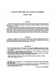
5 Support for Program Development is supported by a prototype of a programming environment designed for hybrid parallel programming (see Fig.4). We have tried to support as much phases of parallel program development as possible using a uniform interface as well as similiar language mechanisms for all steps. The central interactive component is a X-based Graphical Editor running on DecStations (using C++ and the InterViews-3.1 library [23]) which supports the interactive construction of speci cation graphs, the annotation of sequential code to graph nodes and the analysis of graphs w.r.t. structural deadlocks. The Figures 1{3 present screenshots of the editor; in Fig.3, a part of the editor's tool palette is shown, too. An incremental analysis component checks sequential C code annotations w.r.t. declaration of variables, proper typing and consistent usage of communication scripts in corresponding snd/rcv annotations. The C analysis uses the lcc [24] public domain C-frontend as its starting point which has been equipped with functions to generate an annotated syntax tree instead of symbolic assembler code. Meander
GraphEditor Compile Link, Load
Mapping
Transformation Program
Meander Library
sources
Analysis
ANSI-C Sources
Visualization
tracefiles
Meander VisLib
ProgramEditor
WORKSTATION
NFS
TRANSPUTER CLUSTER
Figure 4: Meander system overview The transformation component automatically generates the C source code for a main program for each speci ed process by combining sequential code annotations with template code implementing the graphical constructs as well as a makefile which is used to compile this code on a SUN-hosted Transputer system running HeliosTM [21]. Code generation is supported by the Meander Library (MEAL). It provides a couple of units to organize process systems as well as the communication services which are not directly present in the used target software architecture (e.g. mechanisms for communication handling and distributed termination implemented on top of the socket level of HeliosTM ). The functionality of the library which is also usable as a valid tool of its own, is discussed in more detail in [25]. The analysis component generates a task graph including communication needs for a speci cation graph. The underlying hardware topology is obtained using the Helios resource map and displayed as a graph of processor nodes and communication links. Mapping can be done automatically; alternatively, both graphs may be coloured explicitly by the user. The user is permitted to mark the speci cation graph by visualization attributes. This causes the insertion of function-calls (visualization library) during the transformation phase. The program run produces a tracelog which is used in the editor to animate the program execution on the basis of the speci cation graph. Visualization may be controlled by the user through temporal and logical stepping using a recorder-like interface. 9
6 Conclusions We have sketched the main design decisions for the Meander language and system from the viewpoint of supporting parallel software construction. The experiments with the already functioning prototype show that our strategy to mix up textual and graphical formalisms is a promising way to go. At the current state of the system, enhancing the prototype and adding functionality is of primary interest for the near future. Work on displaying graphs at di�erent folding levels in a manner which looks always nice to the user and still provides realistic response times, a more exact incremental program analysis, the already mentioned port to PVM as well as the development of a more powerful mapping component permitting the speci cation of attributed hardware graphs and the annotation of the process graphs by mapping information known by the user or obtained by analyzing traces from previous program runs is under way.
Acknowledgements The author thanks all colleagues at the programming language group at Siegen University for discussing the design of the language. In particular I am grateful to Clemens Wagner who implemented the rst prototype and the students from the project group Graphical Speci cation of Parallel Processes which have worked hard on the concrete design and implementation of the di�erent aspects of Meander.
References [1] Louis H. Turcott. A survey of software environments for exploiting networked computing resources. Technical Report MSU-EIRS-ERC-93-2, Mississippi State U., Starkville, MS, February 1993. [2] M. Heath. Visual animation of parallel algorithms for matrix computations. In D. Walker and Q. Stout, editors, Proc. Fifth Distributed Memory Conference, pages 1213{1222. IEEE, April 1990. [3] Je� Hollingsworth, Bruce Irvin, and Barton P. Miller. IPS Users Guide Version 5.0. Univ. of Wisconsin-Madison, September 1992. [4] Thomas Bemmerl and Peter Braun. Visualization of message passing parallel programs. In Bouge J. et al., editor, CONPAR92 - VAPP V, LNCS 634 , Lyon, France, pages 79{90, Sep 1992. [5] Ephraim P. Glinert. Visual Programming Environments { Paradigms and Systems. IEEE Society Press, Los Alamitos, CA, 1990. [6] J. Dongarra, D. Sorensen, and O. Brewer. Tools to aid in the design, implementation, and understanding of algorithms for parallel processors. In R. H. Perrot, editor, Software for Parallel Computers, pages 195{220. UNICOM Applied Information Technology, Jan 1992. [7] Dror Zernik, Marc Snir, and Dalia Malki. Using visualization tools to understand concurrency. IEEE Software, 9(5):87{92, May 1992. [8] A. Ferscha. A petri net approach for performance oriented parallel program design. Journal of Parallel and Distributed Computing, 15(4):188{206, August 1992. [9] P. D. Stotts. The PFG language: Visual programming for concurrent computation. In Proc. Int. Conference on Parallel Processing, pages 72{79, 1988. 10
[10] J. Oinonen. GPM { Graphical support for programming multiprocessor systems. Technical Report TR 09478R, University of Joensuu, Joensuu, Finland, Juni 1993. [11] O. Kramer-Fuhrmann and Brandes Th. Gracia - a software environment for graphical speci cation, automatic con guration and animation of parallel programs. In Transputer Anwender Tre�en TAT , Aachen, Germany, Sep 1991. [12] V. S. Sunderam. PVM: A framework for parallel distributed computing. Concurrency: Practice and Experience, 2(4), December 1990. [13] A. Beguelin, J.J. Dongarra, G.A. Geist, R. Manchek, and V.S. Sunderam. Graphical development tools for network-based concurrent supercomputing. In Proc. of Supercomputing 91, Albuquerque, NM, pages 435{444, August 1991. [14] M. Danelutto, S. Pelagatti, and M Vanneschi. High level languages for easy massively parallel programming. Computer and Information Science, 6(3), Oktober 1991. [15] M. van Steen, T. Vogel, and A. ten Dam. ADL: A graphical design language for real-time parallel applications. In Proc. WoTUG, September 1993. [16] Enoch et al. Chan. Enterprise: An interactive graphical programming environment for distributed software development. Technical Report TR 91-17, Univ. of Alberta, Edmonton, Alberta, Canada, September 1991. [17] G. Wirtz. A visual approach for developing, understanding and analyzing parallel programs. In E.P. Glinert, editor, Proc. Int. Symp. on Visual Programming, Bergen, Norway. IEEE, August 1993. [18] G. Wirtz. Developing parallel programs in a graph-based environment. In D. Trystram, editor, Proc. Parallel Computing 93, Grenoble, France. Elsevier Science Publ., September 1993. [19] C. A. R. Hoare. Communicating Sequential Processes. Prentice Hall, Englewood Cli�s, N.J., USA, 1985. [20] American National Standard Institute. American National Standards for Information Systems, Programming Language C, volume X3.159{1989 of ANSI. New York, 1990. [21] Software Ltd. Perihelion. The Helios Operating System. Prentice-Hall, Englewood Cli�s, N.J., 1989. [22] E.L. White and J.M. Purtilo. Integrating the heterogenous control properties of software modules. In H. Weber, editor, Proc. Fifth SIGSOFT Symp. on Software Development Environments, pages 99{108. ACM, December 1992. [23] M. A. Linton, J. M. Vlissides, and P. R. Calder. Composing user interfaces with InterViews. Computer, 22(2):8{22, Feb 1990. [24] C. W. Frase and D. R. Hanson. A code generation interface for ANSI C. Software|Practice & Experience, 21(9):963{988, September 1991. [25] H. Giese, P. Bockmann, and G. Wirtz. Providing CSP-like functionality in a HeliosTM environment. In Proc. 17th. WoTUG Technical Meeting, Bristol, UK. IOS Press, April 1994.
11