Graphic and Haptic Rendering of a 4-DOF Virtual Finger Interacted with the Virtual Object at Multiple Contact Points FENG Miao, LI Jiting , Member, IEEE
I.
Abstract—This paper investigates the simulation of a virtual index finger interacted with an object for a virtual rehabilitation system of human hand. Corresponding to the anatomy of
H
INTRODUCTION
aptic rendering of forces and torques between interactive objects, also known as 6 degree-of-freedom
human hand, the virtual finger is modeled as three phalanges
(DOF) haptics [1], is a difficult problem. As so far it has
which are connected by three joints, which is essentially a
attracted many research interests [2]–[6]. For most researches
4-Degree-of-Freedom (DOF) open chain mechanism. The
no matter how complicated shape the virtual objects might
special characteristic of the virtual finger poses the special issues
have, it is mostly the single part from the kinematic
on graphic rendering, collision detection, and haptic rendering,
perspective.
which is investigated in this paper. Since the interaction only
Haptic rendering for virtual mechanism is especially
occurs on the surfaces of the fingers and objects in the
challenging due to not only the computational complexity
rehabilitation application, triangle mesh representation is used
involved in collision responses at multiple contact points but
to build the geometry model of the virtual hand and the object
also the complicated graphic display of multiple segments
which are both simplified as rigid bodies for the preliminary
which need to satisfy the rigorous kinematic constraints. A
research. A graphic rendering method based on the sequence of
simulation
priority of collision detection is proposed to deal with the
developed by Diego constructs a contact space framework
various contact situations at which the finger contacts the object with
different
phalanges.
The
non-penetration
graphic
rendering is realized by displaying the virtual finger at the position which is closest to the contact point. This position is searched out from the recorded motion trajectory of the finger. The virtual contact forces are modeled upon the spring-mass model and the joint torques are calculated according to the equilibrium equation of moment. The system experiment result demonstrates that the proposed method can provide the satisfactory graphic and haptic display for various contact situations.
system
for
generalized
articulated
body,
which allows the constraint equations for contact and collision to be easily specified [7]. Human finger is essentially an open chain mechanism from the viewpoint of kinematics. The virtual finger may contact with the object at multiple points when it grasps the object. We devote to the investigation on the haptic rendering of the virtual finger grasping the object. The virtual finger is controlled by a hand exoskeleton we developed for motor capability rehabilitation of human hand [8]. The soft tissue is ignored and the phalanges are simplified as rigid segments which are joined in series by rotational joints for preliminary research. The virtual grasped object is also considered as a
Manuscript received October 14, 2010. This work was supported by National Natural Science Foundation of China (Grant No. 50975009) FENG Miao and LI Jiting are with the State Key Laboratory of Virtual Reality Technology and Systems, Robotics Institute, Beihang University, Beijing, China. (phone: +86-10-82338273; fax: +86-10-82317750; e-mail:
[email protected] [email protected].
rigid body. The sequence priority of collision detections for phalanges is determined to realize the non-penetration graphic display meanwhile the phalanges satisfy the constrained position relationship. The interactive forces are modeled upon the spring-mass model and the resulted joint
torques are calculated according to the equilibrium equation of the moment. The proposed method is verified by the
Force Angle Sensor Sensor
Mapping
system experiment and shows that it can provide the realistic graphic and haptic display for various contact situations.
Controller
The rest parts of this paper are arranged as follows. We commence with the introduction of the hand rehabilitation system in Section II. We subsequently propose geometry and kinematic modeling of virtual hand, graphic rendering, and
Calibration
Force Force Feedback Calculation
Device
Collision Detection
Position Kinematics
Model
Graph Rendering
Fig. 2. Work loop of the system
haptic rendering in section III. The experiment is conducted in section IV. The conclusion of our investigation and future work are discussed in section V.
III. HAND HAPTIC INTERACTION MODELS A. Modeling of human hand 1) Kinematic modeling of virtual index finger
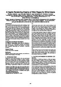
II. THE HAND REHABILITATION SYSTEM As illustrated in Fig.1, the hand rehabilitation system consists of the hand exoskeleton, the controller and the host computer which runs the virtual rehabilitative exercises.
As shown in Fig. 3, the index finger has three phalanges– distal, middle and proximal phalanges, which are connected in sequence by distal interphalangeal (DIP) joint, proximal interphalangeal (PIP) joint and metacarpaophalangeal (MCP) joint to metacarpal. For simplicity, the virtual index finger is modeled as a serial four-bar linkage with four DOFs. The DIP and PIP joints are modeled as one-DOF hinges to realize the flexion/extension motions, while the two-DOF MCP joint is simplified as two one-DOF hinges (denoted by MCP 1 and MCP2, respectively) with orthogonal and intercrossing rotating axis to realize the corresponding motions of flexion/extension and adduction/abduction.
Fig. 1. Hand rehabilitation system
The hand exoskeleton which is actuated by four motors can
Fig. 3. Kinematic model of index finger
comply with the joint motion of the human index finger. The
To determine the positions of phalanges, the classical D-H
joint angles of the finger are measured by the angle sensors
notation is used to establish the local coordinate system for
(potentiometers) and mapped to the virtual finger and thus
each phalange and then the homogeneous transformation
control the virtual finger to execute the virtual rehabilitative
matrix to describe the relative position and orientation of
exercises. The controller runs at the rate of 1000Hz to feed
adjacent phalanges. The lengths of phalanges are set
back the interactive forces, to read sensor data, and to
according to the data in [9]. We omitted the details here.
communicate with the host computer. The work loop of the system is show in Fig.2.
2) Geometry modeling of human hand and object For the preliminary research, the soft tissue of hand is not considered, so the segments of the index finger and the grasped object are both supposed to be rigid.
There are various kinds of geometry models, such as facial
priority of collision detections for phalanges, as shown in
model (e.g. triangle mesh and NURBS Surface) and
Fig.4, and will be interpreted in detail afterwards. In the
volumetric model. The collision detection of volumetric
following parts, for description simplicity, we use the
model is simpler than the triangle mesh model, but it usually
abbreviation GDP for graphic display position, and HCP for
costs large memory. Facial model, especially triangle mesh
haptic device controlled position. We determine the GDP to
model, costs less memory and is suitable for the virtual reality
the position at which the contacts happen. The motion
applications which no interior information of objects is
trajectory of the virtual finger is recorded for the sake of
needed. Since the interaction only occurs on the surfaces of
searching GDP afterwards.
the objects in the rehabilitation application, triangle mesh
Begin
Sequence priority
representation is adopted to model virtual hand and the object. Each phalange is modeled as a single mesh, so there are three
Distal phalange contact with object
meshes for a virtual index finger. The relative positions of the meshes are constrained by the kinematic joints.
Yes
We firstly use SolidWorks software to build the 3D hand model. Then import the hand model into the 3D Max software in order to export the .3ds file for graphic display and .obj file
No
Middle phalange contact with object Yes
No
Proximal phalange contact with object
No
Yes
Seach the contat position from history motion trajectory to determin GDP
Seach the contat position from history motion trajectory to determin GDP
Seach the contat position from history motion trajectory to determin GDP
Display the finger at GDP
Display the finger at GDP
Display the finger at GDP
The finger stops
Proximal And middle phalanges stop ,Distal phalange continues to move with HCP
Proximal phalange stop, distal and middle phalange continues to move with HCP
The finger moves with HCP
for collision detection. The virtual object is created in the same way. B. Graphic rendering We suppose that the palm and the object are both fixed. Because the index finger is composed of three segments, the contact may occur on different phalanges, which results in different graphic display. According to the human hand grasp, when some phalange comes into contact with the object, the
End
contact phalange and all its preceding phalanges (from the palm) stop moving; meanwhile its succeeding phalanges continue to rotate until another contact happens. This process repeats until all the phalanges contact with the object and the finger then stops. The motion of virtual finger should accord with the real hand motion visually. Additionally, in the physical world, when two rigid object contact, there is no penetration. However, because of the limited stiffness of the haptic device the penetration cannot be avoided between the virtual tool and the object. This doesn’t accord with people’s visual perception when two rigid objects come into contact. Therefore, the graphic display should simultaneously satisfy the non-penetration requirement and the aforementioned kinematic constraints. Due to the specialty of the virtual finger, the sequence of collision detection for phalanges is very important to settle the complicated graphic display. We propose a sequence
Fig. 4. Flow chart of the graphic display
The GDP is determined according to different contact situations. If there is no contact occurs, the phalanges are in the free space. The GDP is overlapped with the HCP, as shown in Fig. 5(a). When the contact occurs, the phalanges are displayed in different ways. Without losing the universality, we assume the middle phalange contacts with the object ahead of the others. As has been noted, the GDP of the fingers are determined by searching from the recorded trajectory. Display the finger at the GDP. The middle and proximal phalanges stop, as shown in Fig. 5(b). The distal phalange continues moving with the HCP.
DIP
PIP
to try to approximate the realistic feelings.
GDP/HCP
𝝉1 = 𝑭1 × 𝒓11
(3)
𝝉2 = 𝑭1 × 𝒓12 + 𝑭2 × 𝒓22
MCP
(4)
𝝉3 = 𝑭1 × 𝒓13 + 𝑭2 × 𝒓23 + 𝑭3 × 𝒓33
(5)
where 𝑭1 , 𝑭2 , and 𝑭3 represent the contact force on distal, middle, and proximal phalanges, respectively. 𝒓ij denotes the
(a). No contact occurs
force arm vector for 𝑭𝑖 with respect to the jth joint and is
PIP
DIP
pointed to the ith force action point from the jth joint center,
the subscription 𝑖, 𝑗 = 1,2,3. 𝛕1 , 𝛕2 and 𝛕3 are joint torques
HCP MCP
on DIP, PIP and MCP joints, as shown in Fig. 7.
τ2
GDP F2
F3
r22
GDP3
GDP2
(b). The middle phalange contact with object Fig. 5. Graphic display
τ1 GDP
r11
r13
GDP1
domain, which refers to as the contact between fingers and the object occurs at a fixed point, without the sliding or rolling of
τ3
r12
C. Haptic rendering We confine our simulation task in the static grasping
r33 r23
F1
Fig. 7. Rendering of the joint torques
phalanges over the object. The virtual contact force is modeled upon the spring-mass
IV. EXPERIMENTS
model and calculated with Hooke's law. 𝑭𝑖 = 𝑘 ∗ 𝑑𝑖 ∗ 𝒏𝑖
(1)
𝑑𝑖 = |𝒅𝑖𝐺𝐷𝑃,𝐻𝐶𝑃 ∙ 𝒏𝑖 |
(2)
where 𝑭𝑖 is the contact force at the ith contact point; 𝑘
represents the stiffness coefficient of the object; di is the
projection of the penetration depth at the ith contact point
The experiments are conducted to test the proposed method for graphic and haptic rendering. The VR environment runs on the host computer with the configuration of Intel(R) Core(TM), 2 Duo CPU E8400, 2.99 GHz processor, 2.0 GB memory, an NVIDIA Geforce G100 graphics card, and Windows XP operation system. The total
along the normal direction 𝑛𝑖 which is pointed from object
number of triangular facets got involved in the collision is
vector from the ith HCP of the contact point to the
Collision detection used in our simulation system is a fast
towards the phalange; 𝑑𝑖𝐺𝐷𝑃,𝐻𝐶𝑃 is the penetration depth corresponding GDP, as shown in Fig. 6.
PIP
F2 n2
discrete collision detection library -the PQP library proposed by Ming C Lin. [10].
F3 n3
We suppose that the palm and the object are both fixed on
GDP3
GDP2 HCP3
MCP
HCP2
DIP
1489. The experiment setup is shown in Fig.1.
the ground, and various types of contact have been simulated. The execution time of each calculation loop is 4.2ms in average and not exceeds 5ms, so the update rate is 200Hz,
HCP
GDP GDP1
HCP1
n1 F1
Fig. 6. The virtual contact force rendering
which is acceptable for getting the relative stable force feedback with our exoskeleton force feedback device. Fig.7 shows a displayed position of the virtual finger
The resulted torques acted on DIP, PIP and MCP joints are
grasping the object with all the three phalanges contacting
calculated according to the equilibrium equation of moment
with the object. It can be seen that there is no penetration
between the virtual finger and object. Therefore the graphic
distal phalange contacts with the object in another posture, (g)
rendering is satisfactory.
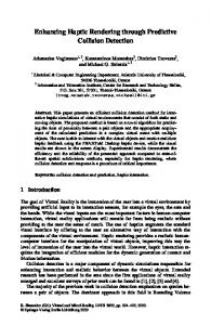
contact occurs only on the middle phalange. The angles are measured from the potentiometers, and the torques are calculated from (3) ~ (5). From Fig.8 we can see that when the whole finger is in the initial position, all the angles and joint torques are zero (see
GDP
Fig.8 (a)). When the contact happens on the proximal phalange, torque is only generated on MCP joint (see Fig.8 (b)). When the middle phalange contacts the object also, then HCP
the PIP joint generates the torque, too (see Fig.8 (c)). When the whole finger contacts with the object, all of the three joints generate the torques (see Fig.8 (d)). This result is quite
Fig. 7. Graphic rendering result
Fig.8 illustrates the virtual grasp procedure with several frames and the corresponding joint angles and torques. The frames are: (a) initial position of the finger in the free space, (b) the proximal phalange contact with the ball, (c) the middle
accordance with the physical grasp. The results also show that the joint torque is also dependent on the contact situations (see Fig.8 (f)) and the postures (see Fig.8 (e) and (g)). We don’t explain in more detail for simplicity.
phalanges also comes into contact, (d) the whole finger grasps the ball, (e) only the distal phalange contacts with the object (f)
(a)
(b)
(c)
(d)
(e)
(f)
(g)
Fig. 8. typical grasps and the results of joint angles and torques
proposed to realize the visually realistic non-penetration V. CONCLUSION AND FUTURE WORK
interaction between the finger and the object. The feedback
In this paper, the kinematic and geometry models of the
joint torques are calculated according to the equilibrium
virtual index finger are built. A graphic rendering method is
equation of moment on the purpose of approximating the
feelings of physical world. With the proposed method, the various types of virtual grasps are able to be conducted with the satisfactory graphic and haptic rendering, such as fingertip grasp, envelop grasp, single-phalange contact, and etc. The method can be applied to the other fingers. Anyway, there is a lot of investigation to be furthered on. We will model the whole hand next, expand the method to more human grasp and manipulation, and consider the deformation of the hand as well as the object. REFERENCES [1]
McNeely, W., Puterbaugh, K., Troy, J., “Six degree-of freedom haptic rendering using voxel sampling”. Proc. of ACM SIGGRAPH, 1999,pp. 401–408.
[2]
Arthur Gregory , Ajith Mascarenhas , Stephen Ehmann , Ming Lin , Dinesh Manocha, “Six degree-of-freedom haptic display of polygonal models”, Proceedings of the conference on Visualization '00, p.139-146, October 2000, Salt Lake City, Utah, United States
[3]
D. Baraff, “ Analytical Methods for Dynamic Simulation of Non-Penetrating Rigid Bodies”, Proc. of ACM SIGGRAPH 1989, 23 (3) , 1989, pp. 223-232.
[4]
W. McNeely, K. Puterbaugh, and J. Troy, “Voxel-Based 6-DOF Haptic Rendering Improvements”, Haptics-e, vol. 3, no. 7, 2006
[5]
M. ORTEGA, S. REDON and S. COQUILLART, “ A Six Degree-of-Freedom God-Object Method for Haptic Display of Rigid Bodies with surface properties”, IEEE Transactions on Visualization and Computer Graphics, VOL. 13, NO. 3, MAY/JUNE 2007, pp 458-469
[6]
Wan and W.A. McNeely, “Quasi-Static Approximation for 6 Degrees-of-Freedom
Haptic
Rendering”,
Proc.
14th
IEEE
Visualization Conf. (VIS ’03) , 2003, pp. 257-262. [7]
Diego C. Ruspini, Oussama Khatib, “Collision/Contact Models for the Dynamic Simulation of Complex Environments” , In 9th International Symposium of Robotics Research (ISRR’99), Snowbird, 1997,pp. 185--195
[8]
Jiting Li, Shuang Wang, Ju Wang, Yuru Zhang, and Guanyang Liu, “Design and Analysis of an Exoskeleton Device for Finger Rehabilitation”, submitted to the 1st intl. Conf. on Applied Bionics and Biomechanics.2010
[9]
B. Buchholz, T. J. Armstrong, and S. A. Goldstein, “ Anthropometric data for describing the kinematics of the human hand”, Ergonomics, 1992, vol. 35, pp.261-273.
[10] http://gamma.cs.unc.edu/SSV/.