Apr 14, 1983 - twits,. pEP k=l where m. w k = Y w(r) k (k = 1,n). r= 1. This means that the inventory of schemes can easily be calculated by substitution of the ...
724
PHASES OF REFLECTIONS FROM MOSAIC CRYSTALS. 1
categories, R or L. It is then necessary to establish which category represents the positive and which the negative phase. This can be done conveniently by considering the averages of the magnitudes of the structure factors in each group. We have arbitrarily utilized the product of the magnitudes of the secondary and coupling terms of each interaction as representative of the magnitude of the n-beam interaction in which they are involved. The products were normalized by setting the value of the largest one to 100. On that scale, the average product equalled 61 for category L and 21 for R. Clearly, the former represented the positive phases. This conclusion was supported by the fact that the largest product in the 'negative' group had a normalized value of only 43. One minor, but possibly confusing, point should be noted. On most chart recordings, the relative locations of maxima and minima will appear in a sequence opposite to that of the calculated ones. The effect is illustrated in Fig. 5. We summarize by noting that there can be little doubt that the phases of reflection triplets can be determined directly from the analysis of n-beam intensities, for centrosymmetric crystals with relatively small unit cells. The extent to which the procedures outlined above can be used, after suitable modification, to determine phases routinely and correctly for non-
3
2
~.
t..alculated Sequence
%
~
..~ Chart
Observed Sequence ] ~ . . . . ~ Fig. 5. Reversal of intensity sequence on chart recording.
centrosymmetric crystals and for crystals with large unit cells remains to be established. References
COLE, H., CHAMBERS,F. W. & DUNN, H. M. (1962). Acta Cryst. 15, 138-144. PALACHE, C., BERMAN,H. & FRONDEL,C. (1963). The System of Mineralogy, Vol. II. New York: Wiley. POST, B. (1975). J. Appl. Cryst. 8, 452-456. POST, B. (1979). Acta Cryst. A35, 17-21. POST, B. (1983). Acta Cryst. A39, 711-718. POST, B., CHANG, S. L. & HUANG,T. C. (1977). Acta Cryst. A33, 90-97. RENNINGER,M. (1937). Z. Phys. 106, 141-176.
Acta Cryst. (1983). A39, 724-736
Graphical Enumeration of Polyhedral Clusters BY F. C. HAWTHORNE
Department of Earth Sciences, University of Manitoba, Winnipeg, Manitoba, Canada R 3 T 2N2 (Received 31 December 1982; accepted 14 April 1983)
Abstract
The following hypothesis is proposed: crystal struc-
metrical isomerism is lost in this graphical representation, but the graphical characteristics are retained. The graph may be completely represented by its
tures may be ordered or classified according to the polymerization of those coordination polyhedra (not
adjacency matrix, a n n × nmatrix [with[~} = N
necessarily of the same type) with the higher bond
independent dements] denoting vertex linkage; it is
valences. The linkage of polyhedra to form clusters is
convenient to represent the N independent matrix elements by the ordered set {a,b,c,...,N}. The collection of all permutations of the vertex labellings that preserve isomorphism is called the automorphism group F(G) of the graph. F(G) is a subgroup of the symmetric group Sn, and the complementary disjoint subgroup of S, defines all distinct graphs whose vertex sets correspond to the (unordered) set {a,b,c,...,N}. However, it is more convenient in practice to work with the corresponding matrix-element symmetries that form
considered from a graph-theoretic viewpoint. Polyhedra are represented by the chromatic vertices of a (labelled) graph, in which different colours indicate coordination polyhedra of different type. The linking together of polyhedra is denoted by the presence of an edge or edges between vertices representing linked polyhedra, the number of edges between two vertices corresponding to the number of corners (atoms) common to both polyhedra. Information on geo0108-7673/83/050724-13501.50
\/-/
© 1983 International Union of Crystallography
F. C. HAWTHORNE a permutation group, denoted P. This particular formation allows the rigorous but natural distinction between graphical and geometrical isomers, and allows systematic investigation of their characteristics. Graphical isomers can be enumerated using P61ya's theorem, by substitution of permitted matrix elements as weight functions into the cycle index of the permutation group P, and can be derived as nonequivalent derangements of the integer set {a,b,c,...,N}. Geometrical isomers can be enumerated for a specific graphical isomer by successively applying P61ya's theorem to the distribution of shared elements over the total dement set of each polyhedron in turn, and can be derived in a similar fashion. The M2(TO4)2~N clusters are considered as an example of this procedure. Introduction
A large number of crystal structures has been determined in the last seventy years, and considerable attention has focused on understanding detailed variations in such structural parameters as bond lengths and bond angles. However, the basic architecture of crystal structures has received relatively little attention. This results from the difficulty in both appreciating and fully assimilating the geometrical details of a threedimensional array of atoms. Two principal methods have been used to describe and visually represent crystal structures. Perhaps the most common and, to date, the most successful method is to represent structures as arrays of connected coordination polyhedra. This has been applied to a wide variety of crystal structures ranging from oxides through chalcogenides to complex alloys and metals, representing the widest variety of bond type. The second method of describing and ordering structures is as two- and threedimensional nets, with the atoms situated at the vertices of the net and the edges of the net representing chemical bonds. As a general vehicle for describing crystal structures, it is not as popular as the polyhedral approach, except within the limits of close-packing and two-dimensional nets when it is primarily used for simple oxides and alloys. General considerations
The general problem of atomic arrangements and their taxonomy is an epistemological one. However, most of the work in this area has involved the classification of specific groups of compounds, and has proceeded in an inductive manner from the observed crystal structures. Notable exceptions to this are the work of Wells (1977, and references therein, 1979) on two- and threedimensional nets, and the work of Moore (1974) on edge-sharing octahedral clusters. The work of Wells
725
(1977) provides both a basis for direct application to crystal structures and a model for further development of complex nets, and work in this area is progressing (e.g. Pearson, 1972; Smith, 1977, 1978, 1979; O'Keeffe & Hyde, 1980). Apart from the work of Moore (1974), all work on polyhedral representations is structure based. This would seem to stem from the fact that there is no general systematic approach to the linkage and organization of polyhedra in three dimensions. The coordination polyhedron approach to structures has led to reasonably successful classifications for some groups of compounds. Typical in this regard are the silicates and the borates, which have been systematized according to the polymerizations of their principal anionic groups. However, such an approach to structure taxonomy is of little use in classes of structures such as the phosphate or the sulphate minerals, or the nesosilicates, in which the principal anionic group does not self-polymerize. In one such example, the phosphate minerals, Moore (1980) has developed a successful classification based o n the polymerization of octahedrally coordinated divalent and trivalent cations. Thus, on the one hand, there are structural classifications involving solely the principal oxyanion of the structural class and, on the other, a classification that does not involve the principal oxyanion of the class at all. These two methods may be improved and integrated together into a coherent approach with the following hypothesis: structures may
be ordered or classified according to the polymerization of those coordination polyhedra with higher bond valences. Such a hypothesis is suggested also by the valence-matching principle of bond-valence theory (Brown, 1978, 1981). As examples, this approach would allow for a more adequate classification of the nesosilicates based on the polymerization of SiO4 tetrahedra and M~0,, polyhedra, and would incorporate the PO 4 oxyanion into the structural classification of the phosphate minerals (cf. Hawthorne, 1979). Many classifications of more complex structures recognize families of structures based on different arrangements of a fundamental building block or module. This is a tightly bound unit within the structure, and can be envisaged as the inorganic analogue of a molecule in an organic structure. Such modules are the basis of structural hierarchies that encompass simple and complex oxides (e.g. Bursill & Hyde, 1972), biopyriboles (Thompson, 1978, 1981), complex sulphosalts (e.g. Wuensch, 1974) and complex alloy structures (e.g. Andersson, 1981; Parth~, 1981). These modules are formed by polymerization of those coordination polyhedra that are most strongly bonded, irrespective of the character of the bonding. The existence of structure modules and their utility in structural description and classification falls within the framework of the above hypothesis.
726
G R A P H I C A L E N U M E R A T I O N OF P O L Y H E D R A L CLUSTERS
Most studies that evaluate structure stability or bonding characteristics do so on a small fragment of the overall structure, an approach that seems to be justified by the results of such calculations (Burdett, 1981, 1982; Gibbs, 1982) and suggested by detailed consideration of bonding in solids (Bader & NguyenDang, 1981). Such fragments generally consist of coordination polyhedra together with their central atoms, and the relative stability of these clusters is assessed according to some a priori criteria, usually involving some kind of energy minimization. The clusters generally considered are the most strongly bonded fragments of the structures under consideration. In this regard, the cluster is the basic module of the structure and the basic philosophy parallels that of modular crystallography. Thus both the modular approach to structural genealogies and the 'molecular' approach to structural stability support the applicability of the above hypothesis on structure hierarchy. All observed polyhedron clusters or modules are fairly stable, just by virtue of their existence; similarly, unstable clusters will never occur, just because they are unstable. Although a truism, the previous statement emphasizes that to understand the stability of such clusters and to evaluate the reliability of our stability criteria, it is necessary to examine all possible clusters consonant with the stoichiometry of interest, and not just those clusters that are observed in structures. Thus the a priori calculation of all possible polyhedron arrangements of interest assumes importance in the study of cluster stability. The hypothesis introduced above may form the basis of a global approach to structure taxonomy. However, both this and a general approach to cluster stability are hindered by the fact that there is no rigorous systematic approach to the linkage and organization of polyhedra in three dimensions. The present study uses some simple results from graph theory and combinatorics to develop a method for the enumeration and derivation of all possible polyhedron clusters, subject to a set of external constraints. These constraints limit an otherwise infinite problem, and can incorporate such factors as fixed number of polyhedra (fixed cation stoichiometry), fixed number of vertices (fixed anion stoichiometry) and limitations on shared elements (for crystal chemical reasons, such as to conform with Pauling's rules).
between vertices denotes the number of atoms common to both polyhedra. Thus one edge between two vertices represents corner sharing between two polyhedra, two edges between two vertices represents edge sharing between two polyhedra, and three edges between two polyhedra represents triangular face sharing, etc. (Fig. 2). The structural representation in Fig. 1(c) is a graph, which may be formally defined as a non-empty finite set of elements called vertices and a finite family of unordered pairs of elements of the vertex set called edges; note that the definition of the collection of edges as a family rather than a set permits the existence of multiple edges, a feature that is crucial to the use of graphs in this context. The graph in Fig. 1(c) is a much simpler representation than the original polyhedral array that is in turn a simpler representation than a conventional 'ball and stick' drawing. The trend of increasing abstraction from Figs. l(a)--,(b)~(c)is accompanied by a loss of information. This can easily be seen in terms of the polyhedral diagram as compared with the 'ball and stick' diagram. In the former, all information on ligand type and isomerism is lost when compared with the latter. Moving from the polyhedral representation to the graphical representation, geometrical information on the polyhedral
(a)
l (b) 3
M2T2~le (d)
(c) Fig. 1. Differentrepresentations of the atom cluster [Mv~T~v (016].
Clusters as graphs
Consider an array of linked polyhedra (Fig. 1). We may represent the polyhedra by the (chromatic) vertices of a graph, in which the different colours indicate coordination polyhedra of different type. The linking together of polyhedra can be denoted by the presence of an edge or edges between vertices representing the linked polyhedra. The number of edges
Fig. 2. Graphical representation of corner-sharing, edge-sharing and face-sharing octahedral dimers.
F. C. H A W T H O R N E linkage is lost. This is illustrated in Fig. 3 which shows two different possible arrangements for the cornerlinked cluster MT2~o12[=-M(T~o4)2~o4]. In Fig. 3(a), the tetrahedra are arranged in a cis configuration relative to the octahedron, whereas in Fig. 3(b) the tetrahedra are arranged in a trans configuration; a single graph represents both configurations which are designated geometrical isomers (cf. Moore, 1974, 1975). Thus the graphical representation has no information on geometrical isomerism. Continuing this process of abstraction, we move from the graph to the cluster formula itself. Here we lose information concerning the types of polyhedral linkage that occur in the cluster. Thus, in Fig. 4, the clusters (a) and (b) are both represented by (a)
(b)
\
/ 2~ 1
3
=MT2®12
727
the cluster formula MT2(Pl 2. The different graphs that correspond to a specific cluster formula are called graphical isomers, and the cluster formula contains no information on graphical isomerism.
Matrix representation The adjacency matrix of a graph with a vertex set {v~,...,v,} is the n x n matrix [atj], in which a u is the number of edges joining the vertices v t and vj. This is a symmetric matrix in which each row or column sum is the degree of the corresponding vertex, that is the number of atoms that the/th polyhedron shares with adjacent polyhedra. An example of a polyhedral array, its graph and the corresponding adjacency matrix is shown in Fig. 5. The adjacency matrix preserves all the properties of the graph, but has the advantage that it is a numerical form rather than a visual form and is thus susceptible to mathematical manipulation. As the adjacency matrix of the graph of a po!yhedral cluster preserves many of the properties of that cluster, we may reverse this procedure and use matrices and their properties to investigate the characteristics of polyhedral clusters. This method has great advantages over visual approaches to the problem. The total number of possibilities may first be enumerated, both to provide a check on the derivation procedure and to indicate whether or not the problem under consideration admits practical solution. Systematic derivation through matrix-element manipulation should not allow the chance of missing possible arrangements that accompanies the more intuitive approach. Various a priori restrictions can be imposed on the enumeration
Fig. 3. Two geometrical isomers of an MT 2 ~012cluster. (a)
(b)
3
/ 1
2~3
21 ~ 3
1 2
1
-
2 2
2
1 -
3
4
1
1
1
3 1 1 - o J MT2(D12
Fig. 4. Two graphical isomers of an MT 2 tpl2cluster,
4
1
1
0
-
Fig. 5. Graphical representation and adjacency matrix represen-
tation of an M2 T2~ot4cluster.
728
G R A P H I C A L ENUMERATION OF POLYHEDRAL CLUSTERS
and derivation procedures. For example, if one does not wish to consider clusters involving face-sharing between tetrahedra, then this constraint is easily imposed by restricting the matrix elements in the relevant part of the matrix to the values 0, 1 and 2.
Cluster stoiehiometry Let there be t types of polyhedra in a cluster, and let a k be the number of polyhedra of coordination number bk; let there be c anions in the cluster. The terms 'cation' and 'anion' are used to distinguish between two types of atoms, one more electropositive than the other; they are not meant to have any connotation with regard to chemical bonding. The 'cluster' represented by the null graph has t
c = Z akbk
and
Yxu=0, t>j
k=l
where xij are the elements of the adjacency matrix. Let us temporarily assume that the anion coordination numbers in the cluster are either [1] or [2]. For each shared vertex in the cluster, c decreases by 1 from its value in the completely unconnected cluster. As the number of shared vertices in the cluster is Y l>jxu, t
C=
~ akb kk= 1
Z Xij" i>J
When higher anion coordination numbers occur in the cluster, this formula must be modified as each entry in the adjacency matrix does not necessarily result in a decreased number of vertices in the graph. Let one of the anions in the cluster be n coordinate (n > 2). Each of the coordination polyhedra that link to this anion thus link to each other and give rise to n(n - 1)/2 matrix elements. Retaining the same stoichiometry but with only two-coordinate anions present results in (n - 1) matrix elements in the corresponding part of the adjacency matrix. This is a difference of (n - 1)(n - 2)/2 matrix elements, and each n coordinate anion in the cluster is equivalent to (n - 1)(n - 2)/2 in ~t>jxu, the sum of the adjacency matrix elements. If r(n) is the number of n-coordinate anions in the cluster (n > 2), the number of anions in the cluster, c, is given by t
C=
r(n).
k=1
in which sk are d u m m y variables and j(k,g) denotes j cycles of length k in the permutation g E Sn. Note that n
~. kj(k,g)= n k=l
constitutes a useful check when dealing with cycle structure. The number of conjugacy classes in S~ is p(n), the number of partitions of the integer n. The elements of the automorphism group F(G) will be restricted to those conjugacy classes whose cycle lengths are less than or equal to the numbers of similar polyhedra in the cluster considered. The conjugacy classes for $4 are shown in Table 1, together with the cluster compositions that are compatible with them. 1. Conjugacy classes for $4 together with
compatible cluster composition C o n j u g a c y class
C o m p a t i b l e cluster
s4t s o s o s o S] S~ S]S o
ABCDq~ A2BC~9.
oo
Sl0 S22 So So
A2B20z
xij= ~. akbk--C + Y ½(n--1)(n--2) r(n).
S~ s2 o s31 s o
Conversely, for a given stoichiometry, the sum of the adjacency matrix elements is given by t
i>j
Inspection of Figs. 1-5 shows that the vertices of the graphs are associated with numbers; thus these graphs are labelled graphs. Formally, a labelling of a graph, G, on n vertices is a one-one mapping from the vertex set of G on to the set of integers {1,2,...,n}. A labelled graph is then expressed as (G,~0), where G is a graph and ¢ is a labelling of that graph. The polyhedral cluster is obviously independent of the way in which the graph is labelled, and thus it is necessary to consider the equivalence of labelled graphs. Two labelled graphs (GI,fPl)and (G2,tP2) are considered the same and called isomorphic if there is a one-one mapping from the vertex set V(G~) on to V(G2) such that both the adjacency and the labelling of the vertices are preserved. This one-one mapping may be considered as a permutation of the vertex labellings, and the collection of all possible permutations of the vertex labellings is the symmetric group S n. The collection of all permutations of the vertex labellings that preserve isomorphism is called the automorphism group F(G) of the graph. F(G) is obviously a subgroup of S n, and the complementary disjoint subgroup of S n defines all labellings of G that are distinct. Each permutation of Sn can be classified according to its disjoint cycle decomposition, and the different permutations can be divided up into different classes, called conjugacy classes, whose structure is denoted by the formal symbol
Table
co
~ a k b k -- ~. X i j + ~ ½ ( n - - 1 ) ( n - - 2 ) k= 1 i>j n= 3
Isomorphic graphs
k=l
n=3
sO oooOsl 1 02 "3
A3B~ ~
A:;z
F. C. H A W T H O R N E The adjacency matrix of a graph with n vertices has elements; however, the matrix is symmetric and the diagonal elements are all unity. Thus the number of n2
independentmatrixelementsN= n(n-1)/2
729
= {1,2,...,N}. The cycle index of P, denoted Z(P), is the average of the cycle structures ofp E P, given by 1
N
= (~). It pEP k= 1
is convenient to designate tile matrix elements [xu; i < j, j increasing monotonically] by the ordered set of integers {a,b,c,...,N}. In terms of the adjacency matrix, equivalent labelled graphs can be considered as derangements of the vertex labellings with the matrix elements fixed, or as derangements of the adjacency matrix elements with the vertex labellings fixed. As we are using and manipulating matrix representations here, the second formulation is more convenient. The group of matrix-element symmetries may be derived by considering the vertex-labelling permutations of the automorphism group and carrying along with these the corresponding rows and columns of the adjacency matrix. It is this group of symmetries, expressed as derangements of the integer set {a,b,c,...,N}, that will be taken into account in the enumeration and derivation of cluster types. If there are t different types of polyhedra in the cluster, then there are
different collections of 2 matrix elements, whose cycles must be disjoint in the matrix element permutations. Let there be ak poly-
hedra of type be with ~k ak = n; there are (2k) matrix elements describing the linkage between type b k polyhedra, and akaj matrix elements describing the linkage between type b k and type b1 polyhedra. The sum over all polyhedral types gives
j=l
[(2k)+'~J~akajl j
= ( ~ ) = N.
Enumeration of graphical Isomers
The enumeration of graphical isomers is of considerable interest, both as part of the actual derivation of clusters and as an intrinsic problem in its own right. The techniques used are those of combinatorial theory, introductions to which are given by Brualdi (1977) and Cohen (1978). McLarnan (1978, 1981a,b,c) gives a lucid development of the important theorems with crystallographic applications to various ordering problems. A brief informal introduction to the important techniques is given here, partly because of the general unfamiliarity of the material and partly to put the material in a notation that is compatible with that used in the rest of the paper. Let P be a permutation group (a subgroup of the symmetric group SN) that acts on the set of integers X
The orbit of
any number k (0 < k < N) is the set of all numbers to which k is sent by the elements of P; this is written as 0(k). The stabilizer of the number k is the set of all permutations of P that leave k fixed; this is written as St(k). Note that ISt(k) 110(k)l = IPI. In terms of equivalent configurations, the importance of an orbit stems from the fact that all elements of an orbit must be equivalent, and thus the number and character of the orbits may be used to delineate equivalent configurations. Important in this regard is Burnside's theorem (unweighted form) which gives the number of distinct orbits associated with P, N(P), as 1 N(P) = ~
IPI
E J(1,P), pEP
where j(1,p) is the number of 1 cycles in the disjoint cycle decomposition ofp. Consider the set of integers X = {1,2,...,N} to be coloured from a set R of M colours, with P permuting colourings of numbers. A whole class of equivalent colourings of the numbers is called a scheme S. The number of schemes ISI is the number of ways of colouring the cycles o f p E P, summed over P. This is given by the unweighted version of P61ya's theorem as 1
IPI
1 PEP
IPl
PEP
where q = •kj(k,p). Both Burnside's theorem and P61ya's theorem may be made far more powerful by introducing the concept of weight. In the set of colours R = { 1,2,..., m }, let each colour r be assigned a weight w(r). If C is a colouring of the integers in X, the weight of C is defined as the product of the weights of the assigned colours. Let X be divided into disjoint subsets X t (i = 1, l) and let S be the set of all colourings that assign the same colour to two elements of X if they are in the same subset Xl. The inventory of S, inv(S), is defined as the sum of the weights of the colourings in S 1
m
inv(S) = l-I Y
w(r)'x''.
1=1 r = l
Returning now to Burnside's theorem, let P permute the elements of X whose elements are weighted by the function w, with the property that if two elements of X are in the same orbit, then they have the same weight. The weight of an orbit 0(k) of P is the common weight of each of its elements. For each element p of P, let fi~(p) be the sum of the weights of all those elements of X that p leaves fixed (i.e. one cycles in the disjoint cycle
730
G R A P H I C A L E N U M E R A T I O N OF P O L Y H E D R A L CLUSTERS
decomposition of p). The weighted version of Burnside's theorem gives the sum of the weights of the orbits of P: IPI 1
The cycle index of the group P, derived from the cycle structure of Table 3, is given as follows:
Z(P) =
"Jgt"~ 1 1[.,15
+ 12Sl S1 S32S6' + 4S~].
wtO(k)l = k=l
P6P
If we now consider X to be the set of colourings of { 1,2,..., N t and not just { 1,2, .... N } itself, the weight of a scheme, or coloured orbit of P, is the common weight of the colourings in it. The weighted version of P61ya's theorem gives the sum of the weights of all the schemes, Z w(S), as 1
Z
y H
twits,
pEP k=l
where m
wk = Y w(r) k (k = 1,n). r= 1
+ 6S~ S~ + 4S~ S~ + 9S~ S~
Let the matrix elements be chosen (coloured) from the set of m integers (colours). From the unweighted version of P61ya's theorem, the number of schemes, IS I, is given by Z(P; m), that is by substitution of the number of integers for the dummy variables Sk: ISI = ~ [ m a5 + 6m ~1 + 9m 9 +4m 7 + 16m~]. If the polyhedra are unconnected or share corners, m = 2, if they are connected, share corners and edges, m = 3,if they are unconnected, share corners, edges or triangular faces, m = 4. Values of lSI for m = 2, 3 and 4 are 1408, 433 377 and 30593 024, respectively. Preliminary enumeration such as this is important at the early stages of study to see if the work is actually feasible; for example, energy calculations on all
This means that the inventory of schemes can easily be calculated by substitution of the weight functions Wk into the cycle index Z(P).
An example Consider a cluster of six polyhedra, three octahedra and three tetrahedra. The general adjacency matrix for this is shown in Table 2. Disjoint cycle decomposition of the elements of the automorphism group F(G) is shown in Table 3, together with the corresponding elements of the automorphism group P that acts on the matrix elements. A summary of the complete conjugacy class structures of F(G) and P are also given in Table 3. Applying the unweighted form of Burnside's theorem, the number of orbits, N(P), is
N(P)=z~[15x 1 + 7 x 6 + 3 +3x9+
x4
1× 12]=3.
This is precisely the case for this example, with the three orbits corresponding to the three different types of matrix elements in the adjacency matrix of Table 2 (that is, linkage between octahedra, linkage between tetrahedra, and linkage between octahedra and tetrahedra. Table 2. Adjacency matrix for a cluster of 3 octahedra
and 3 tetrahedra
o o o
1 2 3
t t t
4 5 6
o
o
o
1
2
3
t 4
t 5
t 6
-
a
b
d
g
k
a
-
c
e
h
l
b
c
-
f
i
m
f
d
e
-
j
n
g
h
i
j
-
o
k
l
m
n
o
-
Table 3. Disjoint cycle decompositions and cycle structures of the automorphism groups F(G) and P for the cluster matrix of Table 2 Disjoint cycle decomposition of Cycle F(G) structure (1)(2)(3)(4)(5)(6) (1)(23)(4)(5)(6) (12)(3)(4)(5)(6) (13)(2)(4)(5)(6) (132)(4)(5)(6) (123)(4)(5)(6) (1)(2)(3)(45)(6) (1)(2)(3)(4)(56) (1)(2)(3)(46)(5) (1)(2)(3)(456) (I)(2)(3)(465) (1)(23)(45)(6) (12)(3)(45)(6) (13)(2)(45)(6) (132)(45)(6) (123)(45)(6) (1)(23)(4)(56) (12)(3)(4)(56) (13)(2)(a)(56) (132)(4)(56) (123)(4)(56) (I)(23)(46)(5) (12)(3)(46)(5) (13)(2)(46)(5) (132)(46)(5) (123)(46)(5) (I)(23)(456) (12)(3)(456) (13)(2)(456) (132)(456) (123)(456) (1)(23)(465) (12)(3)(456) (13)(2)(465) (132)(465) (123)(465)
s~ s,s , s4ts~ s~s z 4t s~s~ s~s~ 4 , s,s~ sLs24 ~ s~sl. s~s~ s~s~ s~s~ s~s~ s~s~ t 3t s~t s~s s',s~s~ s~s~ s~s~ ~¢~
sls~s~ sls~s ~ s~s~ s~s~ s~s~ s,s2s~ ~ ~ s~s,s~~ ~ ~ ~ 3~ sts,s ~ 3~ s,s~s sls~s~ s~ s] s,szs1 , s~s~s~ ~ ' ~ sts,s s~ s~
Disjoint cycle decomposition of P (a)(b)(c)(d)(e)(f)(g)(h)(i)(j)(k)(i)(m)(n)(o) (ab)(c)(d)(ef)(g)(hi)(j)(k)(lm)(n)(o) (a)(bc)(de)(f)(gh)(i)(j)(kt)(m)(n)(o) (ac)(b)(df)(e)(gi)(h)(j)(km)(1)(n)(o) (abc)(dfe)(gih)(j)(kml)(n)(o) (acb)(def)(ghi)(j)(klm)(n)(o) (a)(b)(c)(dg)(eh)(fi)(j)(k)(I)(m)(no) (a)(b)(c)(d)(e)(f)(gk)(hl)(im)(jn)(o) (a)(b)(c)(dk)(el)(fm)(g)(h)(i)(jo)(n) (a)(b)(c)(dgk)(ehl)(fim)(jon) (a)(b)(c)(dkg)(elh)(fmi)(jno) (ab)(c)(dg)(ei)(fh)(j)(k)(Im)(no) (a)(bc)(dh)(eg)(fi)(j)(kl)(m)(no) (ae)(b)(di)(eh)(fg)(j)(km)(l)(no) (abc)(diegJh)(j)(kml)(no) (acb)(dhfgei)(j)(khn)(no) (ab)(c)(d)(ef)(gk)(hm)(il)(jn)(o) (a)(bc)(de)(f)(gl)(hk)(im)(jn)(o) (ac)(b)(df)(e)(gm)(hl)(ik)(jn)(o) (abc)(dfe)(gmhkil)(jn)(o) (acb)(def)(glikhm)(jn)(o) (ab)(e)(dk)(em)(fl)(g)(hi)(jo)(n) (a)(bc)(dl)(ek)(fm)(gh)(i)(jo)(n) (ae)(b)(dm)(el)(fk)(gi)(h)(jo)(n) (abc)(dmekfl)(gih)(jo)(n) (acb)(dlfkem)(ghi)(jo)(n) (ab)(c)(dgk)(eilfhm)(jon) (a)(bc)(dhkegl)(fim)(jon) (ac)(b)(dikfgm)(ehl)(jon) (abc)(dil)(egm)(fhk)(jon) (acb)(dhm)(eik)(fgl)(jon) (ab)(c)(dkg)(eml~i)(jno) (a)(bc)(dlgekh)(fmi)(jno) (ac)(b)(dmgfki)(elh)(jno) ( abc)( dmh )( eki )( flg)(jno ) (acb)(dli)(emg)(fkh)(jno)
Cycle structure sl S sis274 s[s~ sls27 , S~lSJ s~sJ s ',s 2" s,s27 4 s; sz4 s~s~ s]s~ s~s~ sis6, s~s~ ~ , 2 6x s,s2s3s sls~s~s ~ s~s~ s~s~ s~s~ s]s~s~s~ sls~s~s~ s~s~ s~s62 s~s~ sts~s3sr~, 2 s, ~ 2 s,s2s3s ~2 ~i 2 ~ s~s2s~s sls~s~s~ s] s~ s~s~s~s~l, ~ , sls~s~s~ s~s~s~s~t ~ s~ s~
F. C. H A W T H O R N E possible clusters of three tetrahedra and three octahedra would be too much for Methusalah. Let the matrix elements be chosen from the set of four integers {0,1,2,3} with weights {a,b,c,d}, respectively. The inventory of schemes is derived from the weighted version of P61ya's theorem by substitution of the weight functions wk = ~ w ( r ) k = a k + b k + d ' + d
k(k=l,n)
731
Additional information can be incorporated into the inventory if the orbits are coloured from different colour sets. This may be done by using different dummy variables for each orbit in the cycle index for P. Table 4 shows the cycle structure of P without any averaging over different orbits. With the dummy variables s, t and u, the cycle index becomes
Z ( P ) = ~[s, , 3 t 9 u] + 3sl sg t~ tg u] + 3s~ t~ t~ u I u~
r=l
+ 2s~ t~ u~ + 2s] t] u] + %1 s~ tl t~ u] u~
for the dummy variables in the cycle index. Thus + 6s] t] t~ u~ u2x + 6sl s I t] t~ u] + as] t] u]].
inv(S) = ~l[(a + b + c + d) 15 + 6(a + b + c + d) 7 (a 2 + b 2 + c 2 + d2) 4 + 4(a + b + c + d) a (a 3 + b 3 + c a + da) 4 + 9(a + b + c + d) a (a 2 + b 2 + c 2 + d2) 6 + 12(a+b+c+d)(a
2 + b 2 + c 2 + d 2)
x ( a 3 + b 3 + c 3+d3) 2(a 6 + b 6 + c 6 + d 6) + 4(a 3 + b a + c a + da)5]. This expression contains solutions to all questions involving enumeration of 3 + 3 clusters with comer, edge and face-sharing allowed. Setting a = b = c -- d = 1, this equation simplifies to the unweighted form of P61ya's theorem and gives the total number of clusters. The above expression for inv(S) may be expanded, and the coefficient of each term in the simplified expression is the number of arrangements with that particular weight. If we are only interested in a particular set of arrangements with a specific weight, it is much more convenient to evaluate just the coefficient of that particular term using the multinomial theorem. For example, how many 3-3 clusters are there with 5 shared vertices, one shared edge and one shared face? The term of interest in the pattern inventory is thus aSbScd, and the relevant term from the above expression for inv(S) is
aSbScd 36
[(8,1,5,1)+6 {(4,17,1,1)(2,2,4,0) +
2,3,1,1
40t( )(4)/
3,1,0,
+ 0,5,1,1
4,0,0,0
Let the matrix elements be chosen from the sets of integers {0,1,2,3}, {0,1} and {0} with weights {a,b,c,d}-, {a,b} and {a} respectively for the three distinct orbits corresponding to the dummy variables s, t and u. This corresponds to allowing no linkage, corner, edge and face sharing between octahedra, no linkage and corner sharing between octahedra and tetrahedra, and no linkage between tetrahedra in a 3-3 octahedraltetrahedral cluster. From the unweighted version of Pdlya's theorem, the number of schemes, IS I, is given by Z(P; 4,2,1): ISI = ~[43 × 29 × 13 + 3 × 42 × 26 × 13 + 3 × 4 3 x 26x 1 2 + 2 x 4 x 2 3 x
13
+2x4ax
12
23x 1 + 9 × 4 2 x 2 5 x
+6x4x22x
12+6x42x
+ 4 x 4 x 23 × 1] = 1512. This value compares with the 30 593 024 clusters that are possible if all polyhedra are allowed to share corners, edges and faces, and is a good example of how crystal chemical constraints can reduce an otherwise impossible problem to more manageable proportions. Let the matrix elements be chosen from the sets of integers {0,1,2,3 }, {0,1,2,3 } and {0,1,2,3 } with weights {a,b,c,d}, {a,e,f,g} and {a,h,i,j,}, respectively, for the three distinct orbits of P. The inventory of schemes is
Table 4. The cycle structure o f the group P with and without averaging over the different orbits, for the cluster matrix of Table 2 Averaged
÷ 1/ooterms} ÷ 4 {noterms}] Thus there are 8027 3-3 clusters with 5 shared vertices, one shared face and one shared edge.
Not averaged
I s~' . . . . . . . . . . . .
(s~)(s~)(sO
11 33 3 (s's~)(s'sg(s') 3 3 I 1 "-(s,)(s, s2)(s,1 s2) I 3 3 3 4 ........ (s3)(s3)(s,)
6 sTs 4......... I 2 ......... 4
=aSbScd x 8027.
22x 1
s,s3::_" ........
9 sts2 36 ........... 12
I 1 2 I ....... $1S2S3S67" .......
4 s] . . . . . . . . . . . . .
_-
(s~)(sJ)(s])
I I 14 1 1 (sis2)(sls2)(sts2) 1 1 1 1 I (s3)(s3s~)(sls2) (el el~/cl ~o I ° 2 1 ~ 3
el~/cl~ °6/k°3 !
(s~)(s])(s~)
1
3 3 2 2
9
6 6 4
732
G R A P H I C A L E N U M E R A T I O N OF P O L Y H E D R A L C L U S T E R S
derived from the weighted version of P61ya's theorem by substitution of the weight functions
using the multinomial theorem, the relevant term from the pattern inventory is ~6al b 2 c o d o a 6 e2 fO gl a 1 h 1 i 1 jo
S k = ~ w(r) k = a k + b k + c k + d k
(k= l,n)
r= 1
,1,1
m
6,2,
2,1
t g = Z w(r) k = ak + ek + f k + gk ( k = l, n) r=l
+3 ((1,~,1)[(~)+
Uk= ~ w ( r ) k = a k + h k + ik + j k (k = l, n)
"1
r=l
for the d u m m y variables in the cycle index. Thus
x (a + h + i + j)3 + 3(a + b + c + d) x (a 2 + b 2 + c 2 + d2)(a + e + f + g)3
(23,1)}
-s
terms/
+ no more
i n v ( S ) - - ~ [ ( a + b + c + d)3(a + e + f + g)9
(23,1)]
.I
= a 1 b 2 c O a e e 2 fOg1 a 1 h 1 i l j o × 129.
This compares with the previous total of 8027 when the character (orbit) of the shared element is not specified.
x (a 2 + e 2 + f 2 + g2)3(a + h + i + j)3
Enumeration of geometrical isomers
+ 3(a + b + c + d)3(a + e + f + g)3 × (a 2 + e 2 + f 2 + g2)3(a + h + i + j ) × (a 2 + h 2 + i 2 + j2) + 2(a 3 + b 3 + c 3 + d 3) × (a 3 + e 3 + f 3 + g3)3(a + h + i + j)3 + 2(a + b + c + d)3(a 3 + e 3 + f 3 + g3)3 × (a 3 + h 3 + i 3 + j3) + 9(a + b + c + d) × (a ~ + b 2 + c ~ + cl~)(a + e
+ f + g)
× (a' + e 2 + f 2 + g2)( a + h + i + j )
× (a 2 + h 2 + i 2 + j 2 ) + 6 ( a
3 + b 3 + c 3 + d 3)
× (a 3 + e 3 + f 3 + g3)(a6 + e 6 + f 6 + g6) × (a + h + i + j ) ( a 2 + h 2 + i 2 + j2)
+ 6(a + b + c + d)(a 2 + b 2 + c 2 + d 2) × (a 3 + e 3 + f 3 + g 3 ) ( a r + e
6+fr+gr)
× (a 3 + h 3 + i 3 + j 3 ) + 4 ( a 3 + b 3 + c 3 -4- d 3) x (a 3 + e 3 + f 3 + g3)3(a3 + h 3 + i 3 + j 3 ) ] .
As the matrix elements are weighted differently depending on which orbit they are in, we can distinguish between the same type of linkage between different polyhedra, for example edges shared between two octahedra and edges shared between an octahedron and a tetrahedron. As before, let us consider 3-3 clusters with 5 shared vertices, one shared edge and one shared face. However, let us be more specific and specify that we are only interested in clusters where there are 2 corner-sharing linkages between octahedra, 2 corner-sharing linkages between octahedra and tetrahedra, 1 corner-sharing linkage between tetrahedra, 1 edge sharing between tetrahedra and 1 face sharing between an octahedron and a tetrahedron. The term of interest in the pattern inventory is thus a x b 2 c o d o a 6 e2fO gl a 1 h 1 i I jo (a s b 5 c I d I considered earlier);
The enumeration of geometrical isomers corresponding to a specific graphical isomer is also required as part of the process of deriving all possible clusters for a specific cluster formula. Here it is necessary to consider the character of the polyhedra in the cluster, as the relative arrangement of vertices in each polyhedron affects the geometrical isomerism. Consider the adjacency matrix [xt/]; the elements {xo, i = 1, n} are distributed over the vertices, edges and faces of t h e j t h polyhedron. Thus the total number of geometrical isomers is the product of the number of ways in which each matrix row can be distributed over its corresponding polyhedron. As an example, consider a cluster of octahedra and tetrahedra. The automorphism groups for all components (vertices, edges and faces) of the octahedron and tetrahedron are shown in Tables 5 and 6", using the labelling scheme of Fig. 6. * Tables 5, 6 and 10 have been deposited with the British Library Lending Division as Supplementary Publication No. SUP 38519 (9 pp.). Copies may be obtained through The Executive Secretary, International Union of Crystallography, 5 Abbey Square, Chester CH 1 2HU, England. a
f
b k
e
h
¢
d o
g
Fig. 6. Labelling schemes for the corners, edges and faces of an octahedron and a tetrahedron.
F. C. H A W T H O R N E
733
The cycle index of each group is as follows: octahedron:
× (a 4+f4+g4)2+
Z ( P ) - - ~' [ s ,6t12 u s + 3s 4 s ~ t
x(a 6+d 6+e6) z(a+f+g)2
× ( a 4 + b 4 + c 4 ) ( a 4 + d 4 + e4) 3
4u 4 + 6s 2 SEEt 2 t52U4 U2
+ 3s 2 s22 t 6 u24 + 6s23 t 2 t25 u 4 + s~ t62u42
× (a 6 +f6
+ 8s 2 t ] u~ u~ + 6s~ s] t43 u ] + 6s2l s41t34u ] + 8s~ t 2 u 2 u611;
6+c
6)
+ g6)].
Taking the analogous set of weight functions for the tetrahedral group, the pattern inventory is inv(S) = ~ [ ( a + b + c) 4 (a + d + e)6 (a + f + g)4
tetrahedron: Z ( P ) = _2.~[Sll 4 t6
/,/4
+ 6(a + b + c) 2 (a 2 + b E + c2)(a + d + e) 2
÷ 6S] S~ t~ t~ U~ U~ + 3S~ t~ t~ U~
x ( a 2 + d E+e2) 2 ( a + f + g ) 2 ( a
+ 8S I S] t~ UI U~ + 6S~ tz1 t4l ull, where s, t, and u are the d u m m y variables for the vertex, edge and face subgroups respectively. For the octahedral group, let a = unshared element, b - vertex shared with octahedron, c -- vertex shared with tetrahedron, d - edge shared with octahedron, e -- edge shared with tetrahedron, f = face shared with octahedron, g = face shared with tetrahedron. The inventory of schemes is derived from the weighted version of P61ya's theorem by substitution of the weight functions s,=
8(a 6+b
~ w(r)*=a*+b t'+c*
(k=1,26)
r=l
tk = ~ w ( r ) * = a k + d * + e k
(k--1,26)
r= 1
u k= ~ w ( r ) * = a * + f k + ~
(k=1,26)
r= 1
for the d u m m y variables in the cycle index. Thus inv(S) = ~8[(a + b + c) 6 (a + d + e) lz × (a+f+g)S+(a
2 + b 2+c2)a
X ( a 2 + d 2 + e2) 6 ( a 2 + f 2 + g2)4
z+f2g2)
+ 3(a 2 + b 2 + c2) 2 (a + d + e) 2 x ( a 2 + d 2 + e 2 ) 2(a 2 + f E + g z ) 2 + 8(a + b + c)(a 3 + b 3 +
Ca)
x (a 3 + d 3 + e3) 2(a + f + g) x (a 3 + f 3 + g3) + 6(a 4 + b 4 +
C4)
x (a 2 + d 2 + e2)(a 4 + d 4 + e 4) x (a 4 + f 4 + g4)]. These expressions can either be expanded to provide a complete solution, or individual terms can be evaluated as required using the multinomial theorem. An example Consider the graphical isomer (102100001110000) from the previous example of three octahedra and three tetrahedra; the matrix representation is shown in Table 7. The octahedron constituting the first row shares one vertex with another octahedron and two vertices with other tetrahedra. However, the two vertices shared with the tetrahedra are distinct, as tetrahedron 4 links to another tetrahedron, whereas tetrahedron 6 does not; thus the term of interest in the pattern inventory for the octahedral group is a 23 b e 4 C6. Using the multinomial theorem, the relevant term from the pattern inventory is
+ 3(a + b + c) 4 (a 2 + b E + c2)(a + d + e) 4 × (a 2 + d 2 + e2)4 (a 2 + f 2 + g2)4
48
3
1
12
+ no terms
+ 6(a + b + c) 2 (a 2 + b 2 + c2) 2 ×(a+d+e)
2(a 2 + d 2 + e 2 ) ~ ( a + f + g ) 4
× (a 2 + f 2 + g E ) z + 3 ( a + b + c )
(4)(4)+noterms]
2
× ( a 2 + b 2 + c2) 2 ( a 2 + d 2 + e2) 6
× (a 2 + f 2 +g2)4 + 6(a 2 + b E + c2)3 × (a+d+e)
+3 (141)(~)(4)
2(a 2 + d 2 + e 2 ) 5
= a 23 be 4 c 6 x
4.
Table 7. Matrix representation of the graphical isomer (102100001110000)
× (a 2 + f 2 + g2)4 + 8(a 3 + b 3 + C3)2
× (a 3 + d 3 + e 3 ) 4 ( a + f + g ) 2 × (a 3 + f 3 + g3)2 + 6(a + b + c) 2 × (a 4 + b 4 + c 4 ) ( a 4+ d 4+e4) 3 x (a 4 + f 4 + g4)2 + 6(a 2 + b E + c 2)
o o o t t t
1 2 3 4 5 6
o
o
o
t
t
t
1
2
3
4
5
6
-
1
0
1
0
1
1 0
2
2 -
0 0
0 I
0 0
1
0
0
-
1
0
0 1
0 0
1 0
1 0
0
0 -
734
G R A P H I C A L E N U M E R A T I O N OF P O L Y H E D R A L CLUSTERS
For the octahedra of rows 2 and 3, the relevant terms in the octahedron pattern inventory are a 24 b c and a 24 cd; the coefficients of these terms are both 2. For the tetrahedra of rows 4, 5 and 6, the relevant terms in the tetrahedron pattern inventory are a ~2 bc, a u bc and a ~3b respectively; these terms all have coefficients of 1. Thus there are 4 x 2 x 2 x 1 x 1 x 1 = 16 geometrical isomers of this cluster graph; these are shown in Fig. 7.
The
M2(TO4)2(PNclusters
Hawthorne (1979) has shown that the structures of several complex phosphate minerals are based on polymerization of the [M2(TO4)2tp 7] cluster (111110). Similar structural hierarchies in the (T5+O4) 3- and (T6+O4) 2- minerals can be set up based on other [M2(TO4)2tPN] clusters. This way of approaching structural systematics suggests several questions of a more fundamental nature: (i) how many possible [M2(TO4)2tPNl clusters are there, and what are they? (ii) how many of these are likely to be stable, and what are they? (iii) which of these are actually found in structures? (iv) can we forecast the stable and unstable clusters from energy calculations? Using the techniques discussed above, (i) and (ii) can be answered to provide the basis for further investigation of (iii) and (iv). The general adjacency matrix for an [M2(TD4)2tPN] cluster is shown in Table 8, and the disjoint cycle decomposition of its automorphism group is shown in Table 9. The corresponding cycle index, without averaging over different orbits, is as follows:
Z(P)=¼[s~ ~ u l + 3slt~ul], where s, t and u correspond to o-o, o-t and t-t linkages respectively. If both octahedra and tetrahedra have no restrictions on linkage (that is they can be unlinked, share corners, edges or faces), the number of schemes ISI is given by Z(P; 4,4,4):
These may be retrieved by deriving all ordered six-digit combinations of the integers 0,1,2,3 that are distinct under the operations of the automorphism group of Table 9; these are given in Table 10,* thus answering question (i). A little stereochemistry can greatly reduce the dimensions of the problem when considering the possible stable clusters. I am primarily interested in the structures of the sulphate, arsenate and phosphate minerals, and these exhibit certain stereochemical characteristics that allow many of the clusters of Table 10 to be ignored in this context. Firstly, there is no polymerization of (TO 4) tetrahedra (T = S 6+, As 5+, ps+). Secondly, tetrahedra rarely share faces or edges with octahedra. Subject to these constraints, the number of schemes ISI is given by Z(P; 4,2,1): IS I = ¼[4 x 24 x 1 + 3 x 4 x 22 x 11= 28. These are retrieved in a similar manner to those of Table 10; they are listed in Table 11. A scheme in which all of the polyhedra are not linked together is not a cluster, and yet these will also be retrieved by the above procedure. For a scheme to constitute a linked cluster, each row (or column) of its adjacency matrix must contain at least one non-zero matrix element; that is, the scheme must satisfy the general conditions
• x u > O , j = l,n, • ~ lij> 2 ( n - 1),
i=1
i=lj=]
where lij = 1 when x u > O, l u = 0 when x u = O, where x u are the adjacency matrix elements = integers of the * See deposit footnote.
Table 8. Adjacency matrix for a cluster of 2 octahedra
and 2 tetrahedra
ISI =¼[4 x 44 x 4 + 3 x 4 x 42 x 4] = 1216.
0
0
t
t
1
2
3
4 d
o
1
-
a
b
o
2
Q
--
¢
e
t t
3 4
b d
c e
f
f -
9. Disjoint cycle decomposition and cycle structure of 1-(G) and P for the cluster matrix of Table 7 Table
Fig. 7. Geometrical isomers of the graphical isomer (102100001110000). The broken lines represent two possible linkages in each cluster.
Disjoint cycle decomposition of F(G)
Disjoint cycle decomposition of P
(1)(2)(3)(4) (2 I)(3)(4) (1)(2)(43) (2 I)(43)
(a)(b)(c)(d)(e)(f) (a)(bc)(de)(f) (a)(bd)(ce)(f) ( a)( be)( cd)( f )
Cycle structure s~s~sll, ele2el ~1 o2~ ~1o2o]~1 ~2~1 ~1~2~1o2ol ~1
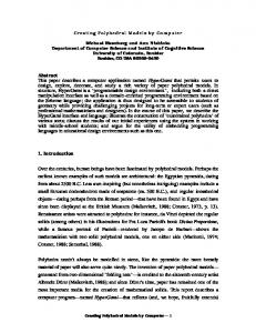
F. C. H A W T H O R N E scheme. Of the 28 clusters in Table 11, only 14 of these are completely connected. Fig. 8 shows the resultant graphs and their corresponding [M2(TO4)2(ffN] clusters. Many of the potential geometrical isomers are not possible without interpenetrant polyhedra, and are not structurally relevant. It is apparent from Fig. 8 that ~0takes the values 6, 7, 8 and 9 only. From Pauling's third rule (Pauling, 1960), one may draw the inference that a major imperative of a structure is the satisfaction of local bond-valence requirements (Hawthorne, 1982). One may conjecture that a more stable cluster is one in which the maximum
GS AP C IR AG LRAPH GEOMETRS IRO MHE IC IO AM LERS oo,,,o
43
101010~ ~ 101100~(~ ~ 011110~
~ ~
~.
735
number of anions have their bond-valence requirements satisfied; these are also the most likely clusters to maintain their integrity in solution, being the most tightly bound together. In the structures of interest here, M = 3 ÷, 2+; T = 5 +, 6 + and thus the anions (oxygens) with (approximately) satisfied bond-valence requirements are those shared between the M and T cations. For each particular stoichiometry, there is only one cluster with the maximum number of satisfied anions; these are summarized in Fig. 9. It is significant that each of the clusters in Fig. 9 is the basis of a considerable hierarchy of structures (Hawthorne, 1979,
GS AP C IR AG LRAPHGEOMETRS IRO MHE C IO AM LERS 111110 201110
~ 301010~
211110~ ~ 201010
301110~
~
~,~ ~
Fig. 8. Completelyconnected clusters for all of the isomers of M2(TO4)2¢p/vcomposition.
@
736
GRAPHICAL ENUMERATION OF POLYHEDRAL CLUSTERS
unpublished), whereas the remaining clusters of Fig. 8 are far less common or absent in natural sulphates, phosphates and arsenates. It would be of interest to calculate the total energy of the clusters in Fig. 8 to see Table 11. Graphs of M2(TO4)2(PNcousters with no t - t linkage and only corner-sharing o-t linkage Cluster graph
tpN
Cluster graph
000000
0
011110 101110 200110 201010 201100 300010
a -
-
-
-
100000 010000
. t
110000 011000 010100 010010 200000
2
001110 100110 101010 101100 2000 I0 300000
-
if a more quantitative approach supports the rather intuitive arguments given here. Financial and moral support was provided by the National Science and Engineering Council of Canada, in the form of a fellowship and grant to the author.
tpN R e f e r e n c e s
5
!
I11110 201110 300110 301010 301100
a ~
211110 301110
. b
311110
7
[M2(TOa)~,(Dr] [M2(TO,)2(D6]
[M2(TO,)2(1)8]
[M2(TO4)2(Dg] Fig. 9. The clusters M2(TO4)2(oN for which the bond-valence requirements of the anions are most nearly satisfied for each value of tpN.
ANDERSSON, S. (1981). Structure and Bonding in Crystals, II, edited by M. O'KEEFFE & A. NAVROTSKY,pp. 233--258. New York: Academic Press. BADER, R. F. W. & NGUYEN-DANG, T. T. (1981). Adv. Quant. Chem. 14, 63-124. BROWN, I. D. (1978). Chem. Soc. Rev. 7, 359-376. BROWN, I. D. (1981). Structure and Bonding in Crystals, II, edited by M. O'KEEFFE & A. NAVROTSKY, pp. 1--30. New York: Academic Press. BRUALDI, R. A. (1977). Introductory Combinatorics. New York: Elsevier North-Holland. BURDETT, J. K. (1981). Structure and Bonding in Crystals, I, edited by M. O'KEEFFE & A. NAVROTSKY,pp. 255--277. New York: Academic Press. BURDETT,J. K. (1982). Adv. Chem. Phys. 49, 47-113. BURSILL, L. A. & HYDE, B. G. (1972). Nature (London) Phys. Sci. 240, 122-124. COHEN, D. I. A. (1978). Basic Techniques of Combinational Theory. New York: Wiley. GIBBS, G. V. (1982). Am. Mineral. 67, 421-450. HAWTHORNE, F. C. (1979). Can. Mineral. 17, 93-102. HAWTHORNE, F. C. (1982). Can. Mineral. 20, 263-270. MCLARNAN, T. J. (1978). J. Solid State Chem. 26, 235-244. MCLARNAN, T. J. (198 la). Z. Kristallogr. 155, 227-245. MCLARNAN, T. J. (198 lb). Z. Kristallogr. 155, 247-268. MCLARNAN, T. J. (1981c). Z. Kristallogr. 155, 269-291. MOORE, P. B. (1974). Neues Jahrb. Mineral. A bh. 120, 205-227. MooRE, P. B. (1975). Neues Jarhb. Mineral. Abh. 123, 148-159. MOORE, P. B. (1980). International Mondial du Phosphate: Second International Congress (Boston), pp. 105-130. O'KEEFFE, M. & HYDE, B. G. (1980). Philos. Trans. R. Soc. London Ser. A, 295, 553-623. PARTH~, E. (1981). Structure and Bonding in Crystals, II, edited by M. O'KEEFFE & A. NAVROTSKY, pp. 259--296. New York: Academic Press. PAULING, L. (1960). The Nature of the Chemical Bond, 3rd ed. Ithaca, New York: Cornell Univ. Press. PEARSON, W. B. (1972). The Crystal Chemistry and Physics of Metals and Alloys. New York: Wiley. SMrrH, J. V. (1977). Am. Mineral. 62, 703-709. SMrrH, J. V. (1978). Am. Mineral. 63, 960-969. SMITH, J. V. (1979). Am. Mineral. 64, 551-562. THOMPSON, J. B. JR (1978). Am. Mineral. 63, 239-249. THOMPSON, J. B. JR (1981). Structure and Bonding in Crystals, II, edited by M. O'KEEFFE & A. NAVROTSKY,pp. 167--196. New York: Academic Press. WELLS,A. F. (1977). Three-Dimensional Nets and Polyhedra. New York: Wiley-Interscience. WELLS, A. F. (1979). Further Studies of Three-Dimensional Nets. A CA Monogr. No. 8. WUENSCH, B. J. (1974). Sulfide Mineralogy (MSA Short Course Notes), W 1-W44.