Subsequently, the two contact points (shown as dots), each .... H 2£H 3 @34 e. (6). 3 Finger Localization. In this section, we add one more finger А$ , also with ...
Appeared in Proceedings of the 2000 IEEE International Conference on Robotics and Automation.
Grasping Curved Objects through Rolling Yan-Bin Jia Department of Computer Science Iowa State University Ames, IA 50011-1040
Abstract
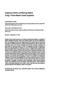
ary independently, as shown in Figure 1(a). In response to the rolling of the fingers, the object starts moving as well. Subsequently, the two contact points (shown as dots), each between one finger and the object, move along the boundaries of the (corresponding) fingers and the object. The tactile sensors mounted on the fingers record two contacts simultaneously, one on each finger. As the rolling continues, the sensors record a few more pairs of simultaneous contacts at multiple time instants. Using these contact data, the fingers then estimate the contact locations on the object’s boundary, thereby localizing themselves relative to the object (see Figure 1(b)).
Grasping a curved object free in the plane may be done through rolling a pair of fingers on the object’s boundary. Each finger is equipped with a tactile sensor able to record any instantaneous point contact with the object. Contact kinematics reveal a relationship between the amount of finger rotations and the total curvatures of the boundary segments of the fingers and the object respectively traversed by the two contact points during the same period of rolling. Such relationship makes it possible to localize both fingers relative to the object from a few pairs of simultaneously taken finger contacts at different time instants. A least squares formulation of this localization problem can then be solved by the Levenberg-Marquardt algorithm. Simulation results are presented. After localization, a simple open loop strategy is used to control the continual rolling of the fingers until they simultaneously reach two locations on the object’s boundary where a grasp is finally performed.
(a) Touch
(b) Roll
1 Introduction Contact friction cone
In this paper we look at how to grasp an object free to move in the plane using two fingers. We consider point contacts only. The fingers can translate and rotate. Each finger has a tactile sensor able to locate the position of its contact with the object on the finger boundary. Below we give a brief overview of the grasp procedure to be described in this paper. At the initial state, both fingers are in touch with the object. We assume that contact friction between the object and the fingers is large enough to prevent any possible slips, which is realistic when the angular velocities of both fingers are kept small. In order to determine their positions relative to the object, the fingers start rolling on its bound-
Figure 1: Achieving a grasp of an object by rolling two fingers on its boundary. (a) The configuration before sensing starts. (b) The configuration right after four pairs of simultaneous contacts (drawn as solid dots) were collected since (a). The fingers now have located themselves on the object boundary. (c) The configuration before an antipodal grasp is applied.
Support for this research was provided in part by Iowa State University, in part by University of Minnesota, and in part by Defense Advanced Research Projects Agency during the author’s short term stay at University of Minnesota.
After the localization, the fingers continue rolling, now controlled by some strategy, to simultaneously reach two precomputed boundary points of the object where it can be
(c) Grasp
�
1
grasped by the fingers exerting forces along the two inward normals (Figure 1(c)). The angular velocities of the fingers are small enough so that the fingers can halt almost instantly. The above grasping strategy bears some resemblance to human grasping that takes advantage of the tactile capability of the human fingers. Most traditional strategies for robot grasping do not disturb the object’s pose, which is assumed to be known, and rely on almost perfect finger placements at some precomputed boundary points of the object. Our strategy actively explores the object to “calibrate” the fingers against it before a grasp. This is more robust against disturbances.
ing object with known angular velocity can be recovered from the readings on two linear tactile sensors passively in contact with the object. In the author’s previous work [8] jointly with Erdmann, a finger pushes a known object in the plane and estimates its pose as well as motion from the movement of the contact on the fingertip. In this paper, we are only interested in the relative configuration of an object to the fingers. So dynamics are not used.
�
1.2 Notation
�
To avoid any ambiguity, the notation ‘ ’ means differentiation with respect to time, while the notation ‘ ’ means differentiation with respect to some curve parameter. For example, gives the velocity of a point moving on a curve . A scalar in a cross product (e.g., the angular velocity in ) acts as a vector of equal magnitude and orthogonal to the plane. The normal of a closed twice continuously differentiable curve bounding a connected region in the plane is always chosen to point inward. Accordingly, the curvature of such a curve is positive everywhere it is convex, and negative everywhere it is concave.
��� ��� � � �
� � � ��� ��� � �� � ��� �
1.1 Related Work Montana [11] derived a set of differential equations describing the motion of a point contact between two 3dimensional rigid bodies in response to their relative motion. In our problem, the object’s motion is unknown, so is its relative motion to the fingers. Cai and Roth [2] also studied the kinematics of spatial motion with point contact. The special kinematics of two rigid bodies rolling on each other was considered by Li and Canny [9] in view of path planning. Incorporating dynamics as well, Cole et al. [4] devised a strategy to control an object grasped in a multifingered hand to track a prescribed trajectory. Force-closure grasping was studied by Mishra et al. [12] and by Markenscoff et al. [10] on the number of (frictional and/or frictionless) fingers sufficient for gripping 2- and 3D objects. The first work also provided an efficient lineartime algorithm for grasp synthesis under a wide-range of conditions. Blake and Taylor [1] gave a geometric classification of two-fingered frictional grasps of smooth contours. Hong et al. [7] showed that two and three finger grasps exist with friction for 2- and 3-D smooth objects. They also introduced an approach for rotating planar objects based on finger gaits. Reactive grasping algorithms were studied earlier by Teichmann and Mishra [16] who employed distance and angle sensing coupled with a potential function to search for a grasp of an unknown convex object without disturbance. The caging work by Rimon and Blake [14] was on how to confine a given 2-dimensional object using a two-fingered hand under one degree of control. Salisbury [15] first proposed the concept of fingertip force sensing with an approach for determining contact locations and orientations from force and moment measurements. Grimson and Lozano-P´erez [6] used tactile measurements of positions and surface normals on a 3D polyhedron to locate and identify it from a set of known polyhedral. Erdmann [5] showed that the local geometry of a rotat-
2 Kinematics of Rolling
�
�
� �� �
We begin with a kinematic study of the case of one finger rolling on one object . The finger is moving at velocity and rotating at angular velocity . The object meanwhile has velocity and angular velocity .
�
�
�
���
B
α’
F
α( u) ω
ωB β( s )
vB
β’
v
Figure 2: Finger
� �
�
rolling on object .
�
�
Denote the boundaries of and by curves and , respectively. These two curves are assumed to be at least twice continuously differentiable. They are also assumed to be regular, that is, the first order derivatives of and do not vanish anywhere. The corresponding curvature functions are and , respectively. The two points in
!�
2
!#"
�
�$� ��� �&% � � � ! � � �'�)( ! " �&% �+*-,/. � �0 � 0 �21 0� � 0 �31
− ω
contact are denoted by and in the local frames of and , respectively. To guarantee point contact, the condition holds. To simplify our derivation of contact kinematics, we first consider that both and are unit-speed curves; in other words, and . The velocity of the moving contact point in the world coordinate frame has two equivalent forms:
− β( s ) ωB β( s )
� ( �4�65 � ( 5 � � � � � ��� ( �� �7�658�9 ( 58�9 � %;� : (1) � where 5 is the orientation of and 58� the orientation of � . Under rolling, the two points in contact, fixed on � and , respectively, must have the same instantaneous velocity, that is, (2) � ( ��?�75@�@@A Meanwhile, the tangents of � and must be opposite to each other at the contact, satisfying 5 � � ( 5 � � �CB A (3)
α( u ) ω Figure 3: Two fingers rolling on one object.
�P
�
�
tween the integrals of curvature over the four curve segments traced out by the two contacts, respectively, and the rotation of the fingers during a rolling period.
� � P �P �$� ���
In this section, we add one more finger , also with boundary , and consider the rolling of both fingers and on . Our objective is to determine the locations of and based on how the contacts move on their boundary during the rolling. We continue to use the notation in Section 2 so that and locate the contact between and . The contact between and is on and on , respectively,
�
� ��� �
P � �Q� �'P � � P
�
� %P � � �
�
� � � D %R� � ! � ��'��S( D !#� " �T% �#U (7) � � P � � D %RP� � ! � ��'��S( D ! � P " � % � A (8) � P P Eliminate the object’s angular velocity ��� from (7) and (8): � � ! � � ��� D % � !#" �&% �S( � � � P � ! � � �VP � D %P� !W" � %P �)( �XP A (9) We then integrate both sides of the above equation over a time period � OZY : O . � of rolling, obtaining [ ]\ � D [4` \ �T% � % ( [ �&\
[�_ ]^c \ ! � I [R` ^ `c \ !W" I [ �a^ �&\ � IbO � c ! � I � D `c !W" �T% � I % ( � P IbO A (10)
_^ ^ �a^ � � % 3 � e % � � � V � d � & d � d f d � ' � d � f d � where , , P , and % P d � %eP � O dT� , O O O P � h : 1 , for g . �\ �\ The two integrals i �a^ � I;O and i �a^ � P I;O are the angles of rotation completed by the two fingers during the same period � OZY : O . � . Equation (10) describes the relationship be-
� � �ED %F� � ! ��� ( D ! � " A (4) � If � is not necessarily unit-speed, there exists a reparameterization of � using the arc length function � G � � G � ��� so that �$� � � ��G �H� becomes unit-speed. Since � � �JI � � �JI � � G I �� G : I I I � L
K � M �8. N M holds. Therefore it follows that � � � I �� G I � G � 0 � � 0���� ! D ( � ! " � A (5) � I I;O Similarly, the moving rate of the contact on � is %@� � � � � D � ( � � A (6) 0� 0 ! � ! " �P
�P
as shown in Figure 3. Denote by the angular velocity of . Once again for clarity and simplicity, we assume that both and are unit-speed. General curves can be easily dealt with. There are now two sets of contact kinematic equations (4):
Equations (1), (2), and (3) can be easily solved [8] to yield the contact kinematics of rolling:
3 Finger Localization
α( u− )
i L� ^ \ !: � � I � j Y .�k
3.1 Total Curvature
�
�
The integral is called the total curvature of the curve over . Let the tangent of at the contact be and the corresponding normal be . Let angle represent the orientation of .
l
o p]qsrtp]u
l � ���
m
n
Here is the two-dimensional version of the relative curvature form introduced by Montana [11].
3
∆T T (u+∆ u)
∆φ
T0
T( u ) T1 T2
s0
s2
s3
-
T0
% %P� . %. %P .
%P .
� % Y D � . (� Y : � %P Y D � P . ( � P Y A
�P O .4 O v vv O
-
T0 T3
-
T1
∆φ 1
[ _ � D [-` ^' _a� _^ % ( d
[�_ ^c ! � I [R` ^ `c ^ c c ^ ! " I � c ! � I � D `c !#" I % ( ]P d :
_^ ^ for g �1;: AhAA : . (11) � � Here ]d � i �a^ � I;O and ]P d � i �a^ � P I;O . To simplify the notation, for 1/ g - let d �&% Y : %P Y � � [-` ^ ' � ^ !#" I %9D [� � �&¡¦D§ � «O ª9¬ � ¡¦P D P �V O ª9¬
( ��� : ( ����A
We simulated the finger localization procedure. Circular fingers were used because their constant local geometry simplifies the computation. All fingers used in our simulations were of this type. Objects in the simulations had elliptic and closed cubic spline boundaries. Figure 6 shows a sample simulation. For the ease of coding, only constant
β(b ) β(a )
� P¡ � %¥P� �
5 Simulations
− F
β(a- )
F
&� ¡ � � %8� ��¡¢D£#¤
and too fast to maintain the rolling contact. Let be the present contact locations on . We may choose to move the contacts at constant speeds and , by applying the following control laws:
− F
β(b ) F
Figure 5: Rolling two disk-like fingers to form an antipodal grasp. The two disks are rolling from their current configurations (drawn with solid circular boundary) to reach their goal configurations (drawn with dashed circular boundary) simultaneously where they can form an antipodal grasp of the curved object. Note that the object has its own motion in response to the rolling.
for finding antipodal points were studied by Chen and Burdick [3]. The grasping problem has essentially become how to control the nonlinear system defined by the kinematic equations (7) and (8). We first look at how to estimate the object’s angular velocity . Since can be sensed or computed, we know the object relative to the fingers and . Suppose and can localize themselves in the world coordinate system. We thus can compute the orientation of during rolling, thereby able to estimate by, say, finite differencing. The details are omitted here. With estimated, a simple open-loop strategy can be employed for the control of and . Set to be the amount of time that we expect both fingers to reach the antipodal positions and , as shown in Figure 5. We can always choose large enough so that neither finger rotates
� : � P ;% : %P �
�
��� �P
�P
��
���
�
� �
� P �
�
�P
V®¯/°H±²W®³Z´�µ
¶'®h·/°H±h²®³Z´�µ
�o � »®¼ ¸t¹bº ¯X°H±²e®³Z´�µ
Figure 6: A localization example. The disks and rotate at and , respectively, while the object bounded by a concave cubic spline rotates at . A pair of disk contacts is recorded every sec in a 3-second period. The scenes (a), (b), (c), (d) respectively represent the initial configuration, the configuration after 3 seconds, one random guess of the initial configuration, and the resulting estimate. Note the slight difference in disk placements between (a) and (d). Such estimation error was later eliminated using multiple guesses.
�
angular velocities were considered. This would be unrealistic for a real object rotating passively in response to the rolling of the fingers. Since the formulation of the localization problem (12) depends directly on the amounts of
The normals of at these two points must be opposite to each other and also coincide with the line segment joining the two points.
5
finger rotations rather than on the angular velocities, it is hard to see that the outcomes would have been affected had realistic velocities been used. With single guess on an initial finger placement, failures of localization often occurred when the guesses were quite far from the actual placements. In such a case, the Levenberg-Marquardt algorithm was trapped in a local minimum of the least squares objective function (12). To cope with this limit of the algorithm as a local optimization method, we used multiple random guesses on the finger placement, and selected the one that generated the smallest value of the objective function. This approach was successful in most of the trials. Another possibility is to use a more sophisticated nonlinear programming method, for instance, simulated annealing, to escape local minima.
on finger localization, finger motion control, and implementation with an Adept Cobra 600 robot. Acknowledgement Many thanks to Bud Mishra for a number of valuable suggestions on improving the technical completeness of the paper and on sensor implementation. Thanks to Steve LaValle for a discussion and for his help on installing the LEDA software package. The author also thank the anonymous reviewers for their valuable feedback.
References [1] A. Blake and M. Taylor. Planning planar grasps of smooth contours. In Proc. of the IEEE Intl. Conf. on Robot. and Automat. pp. 834–839, 1993. [2] C. Cai and B. Roth. On the spatial motion of a rigid body with point contact. In Proc. of the IEEE Intl. Conf. on Robot. and Automat. pp. 686–695, 1987.
6 Summary and Future Work
[3] I-M. Chen and J. W. Burdick. Finding antipodal point grasps on irregularly shaped objects. In Proc. of the IEEE Intl. Conf. on Robot. and Automat. pp. 2278–2283, 1992.
We have introduced an approach that combines sensing and grasping for the manipulation of planar curved objects. Two fingers with tactile capability actively localize themselves relative to an object through rolling on its boundary and recording multiple contacts in synchronization. After the localization, a grasp of the object is attained by controlling the rotation rates of the two fingers to drive their contacts with the object to a pair of antipodal locations. Based on the kinematics of rolling, finger localization is done by reducing the discrepancy between the fingers’ tactile data and the estimated total curvatures of the object’s boundary segments traversed by the fingers. The global control problem of moving the fingers to the antipodal positions may be reduced to a local one by replacing the fingers at the estimated antipodal positions (therefore in the vicinity of the actual positions). Finger localization after the replacement would also become easier due to the local nature of the Levenberg-Marquardt procedure. Based on rolling kinematics the localization problem is transformed into a purely geometric optimization. The finger rotation can be controlled very slow. However, in implementation the issue of force control is very important. The forces include dynamic forces exerted by the fingers on the object, contact friction between them, and support friction between the object and the table. Quasi-static analysis can provide us a qualitative estimate of the object’s motion, which may then be used for finger control. The results in this paper have the potential to combine sensing, shape recognition, and grasping in a smooth way to resemble the dexterity of human manipulation. They represent one step towards the integration of sensing and manipulation. The undergoing and future work include improvement
[4] A. A. Cole, J. E. Hauser, and S. S. Sastry. Kinematics and control of multifingered hands with rolling contact. IEEE Trans. Automatic Control, 34(4):298–404, 1989. [5] M. Erdmann. Shape recovery from passive locally dense tactile data. In P. K. Agarwal et al., ed. Robotics: The Algorithmic Perspective, pp. 119–132. A. K. Peters, Boston, MA, 1998. [6] W. E. L. Grimson and T. Lozano-P´erez. Model-based recognition and localization from sparse range or tactile data. Intl. J. Robot. Res. 3(3):3–35, 1984. [7] J. Hong, G. Lafferriere, B. Mishra, and X. Tan. Fine manipulation with multifinger hands. In Proc. of the IEEE Intl. Conf. on Robot. and Automat. pp. 1568–1573, 1990. [8] Y.-B. Jia and M. Erdmann. Pose and motion from contact. Int. J. Robot. Res. 18(5):466–490, 1999. [9] Z. Li and J. Canny. Motion of two rigid bodies with rolling constraint. IEEE Trans. Robot. Automat. 6(1):62–72, 1990. [10] X. Markenscoff, L. Ni, and C. H. Papadimitriou. The geometry of grasping. Intl. J. Robot. Res. 9(1):61–74, 1990. [11] D. J. Montana. The kinematics of contact and grasp. Intl. J. Robot. Res. 7(3):17–32, 1988. [12] B. Mishra, J. T. Schwartz, and M. Sharir. On the existence and synthesis of multifinger positive grips. Algorithmica, 2(4):541–558, 1987. [13] W. H. Press, B. P. Flannery, S. A. Teukolsky, and W. T. Vetterling. Numerical Recipies in C. Cambridge University Press, Inc., 1988. [14] E. Rimon and A. Blake. Caging 2D bodies by 1-parameter two-fingered gripping systems. In Proc. of the IEEE Intl. Conf. on Robot. and Automat. pp. 1458–1464, 1996.
6
[15] K. Salisbury. Interpretation of contact geometries from force measurements. In M. Brady and R. Paul, ed. Robotics Research, pp. 565–577. The MIT Press, 1984. [16] M. Teichmann and B. Mishra. Reactive algorithms for 2 and 3 finger grasping. In Proc. of the IEEE/RSJ Intl. Conf. on Intell. Robots and Sys. 1994.
7