Laminated bamboo has several applications in the construction industry and is excellent in its ... Figure 2.2 Savill Garden Pavilion . ... Figure 3.8 Unstrained gridshell form finding, showing hanging chain-like-model (Picture from Rhino3D) ... 23.
Gridshell structures in laminated bamboo Author Omar Elnagar
Supervisor Dr. Bhavna Sharma
The University of Bath Department of Architecture and Civil Engineering
April 2017
MEng AR30315
Acknowledgements I would like to express my sincere gratitude to Dr. Bhavna Sharma for supervising this research. I would also like to thank my parents Akram Elnagar and Amanda Salah, for their continuous support in everything I go through. They have supported me in their ease and hardship, and have always been there when I needed them. Finally, I want to thank all my friends who supported me, particularly my friend Ali Abubaker for his continuous and staunch support.
Abstract
Laminated bamboo has several applications in the construction industry and is excellent in its properties. These applications range from hand built cranes to houses. However, the industry is not confident in extending bamboo capabilities to further structures due to the lack of research which supports its use. Laminated bamboo has exceptional mechanical properties; therefore, this research will study if building gridshell structures can be enhanced by using of laminated bamboo as a material. The main purpose of gridshells is to cover long span areas with low cost and light structures. Laminated bamboo can satisfy this need.
This research studies the strength of strained gridshell structures in the erection process. It also asses the strength of unstrained and strained gridshells in resisting asymmetric load. Currently most gridshells are built out of timber or steel. Hence, the behavior of laminated bamboo will be compared with western hemlock timber and steel in their application to gridshell structures.
The tests will be made on a computer model built using a dynamic relaxation method and assessed using non-linear analysis. This model represents a 10m by 10m simple gridshell in plan. Attention is given to the deflection behavior of the models and analysis of bending actions.
LIST OF FIGURES Figure 1.1: (Princeton University , 2013) Forces in continues shell and gridshell............................................. 6 Figure 1.2: Raw bamboo (Zenbamboo, 2017) .................................................................................................. 8 Figure 2.1 Mannheim Bundesgartenschau Multihalle .................................................................................... 14 Figure 2.2 Savill Garden Pavilion ..................................................................................................................... 14 Figure 2.3 British Museum Great Court roof gridshell (Foster+Partners, 2000) ............................................. 15 Figure 2.4 ZCB Bamboo Pavilion (Chinese University of Hong Kong, 2015) .................................................... 16 Figure 3.1 Grasshopper addition component (Picture from Grasshopper3D) ................................................ 18 Figure 3.2 Unstrained gridshell form finding procedure ................................................................................. 19 Figure 3.3 Grasshopper definition for 'Assemble Model component' and Large Deformation analysis' with laths properties ....................................................................................................................................... 20 Figure 3.4 Strained gridshell form finding procedure ..................................................................................... 20 Figure 3.5 Strained gridshell erection model boundary conditions (perspective) (Picture from Rhino3D).... 21 Figure 3.6 Strained gridshell mid-span lifting sequence, left to right (2 pinned, 2 rollers supports) (Picture from Rhino3D) ........................................................................................................................................ 22 Figure 3.7 Erected gridshell showing lifting force at mid-span with initial positions shown as crosses (Picture from Rhino3D) ........................................................................................................................................ 22 Figure 3.8 Unstrained gridshell form finding, showing hanging chain-like-model (Picture from Rhino3D) ... 23 Figure 3.9 Unstrained gridshell form found geometry in compression (Picture from Rhino3D) .................... 23 Figure 3.10 Unstrained gridshell initial model boundary conditions (perspective) (Picture from Rhino3D).. 23 Figure 3.11 Strained Method procedure ......................................................................................................... 25 Figure 3.12 Unstrained Method procedures ................................................................................................... 25 Figure 4.1 Front view of erected gridshell visualising maximum curvature as circle, erection loads and showing curvture graph ........................................................................................................................................ 27 Figure 4.2 Curvature and height of both gridshells. (Blue) Laminated bamboo, (Red) Western Hemlock (Picture from Rhino3D) ........................................................................................................................... 27 Figure 4.3 Load definition. Perspective view. (Picture from Rhino3D) ........................................................... 28 Figure 4.4 Load definition. Green arrows representing load. Blue lines represent the gridshell (Picture from Rhino3D) ................................................................................................................................................. 28 Figure 4.5 Erected shape deflection and load results comparison ................................................................. 29 Figure 4.6 Comparison of deformed shapes with stress colours .................................................................... 29 Figure 5.1 Load definition for unstrained gridshell ......................................................................................... 30 1|Page
Figure 5.2 Steel unstrained gridshell deformed shape (scale 4 times) ........................................................... 31 Figure 5.3 Western hemlock unstrained gridshell deformed shape (scale 4 times) ....................................... 32 Figure 5.4 Laminated bamboo unstrained gridshell deformed shape (scale 4 times) .................................... 32
LIST OF TABLES Table 2.1 Material properties of raw bamboo, laminated bamboo and western hemlock timber. ............... 12 Table 4.1 Maximum bending stress calculations (for reference check Table 2.1) .......................................... 26 Table 4.2 Erection loads and curvature results comparison ........................................................................... 26 Table 5.1 Steel material properties ................................................................................................................. 30 Table 5.2 Deflection and load results .............................................................................................................. 31
2|Page
CONTENTS List of Figures ......................................................................................................................................... 1 List of Tables .......................................................................................................................................... 2 Contents ................................................................................................................................................ 3 1.
2.
Introduction................................................................................................................................... 5 1.1.
Engineers and architects’ relation to shells ............................................................................. 5
1.2.
Form and environment........................................................................................................... 5
1.3.
Forces and Gridshells motivation ............................................................................................ 6
1.4.
Modelling + Form finding ....................................................................................................... 6
1.5.
Fabrication and construction .................................................................................................. 7
1.6.
Gridshell aesthetic ................................................................................................................. 7
1.7.
Typical Materials .................................................................................................................... 7
1.8.
Bamboo ................................................................................................................................. 8
1.9.
Aims and Objectives ............................................................................................................... 9
Literature Review......................................................................................................................... 10 2.1.
What is a gridshell? .............................................................................................................. 10
2.1.1. 2.2.
Materials ............................................................................................................................. 11
2.2.1.
Laminated Bamboo Mechanical Properties .......................................................................... 11
2.3.
Dynamic relaxation (form finding method) ........................................................................... 13
2.4.
Timber gridshells (Case Study) .............................................................................................. 13
2.4.1.
Mannheim Bundesgartenschau Multihalle ........................................................................... 13
2.4.2.
Savill Garden .......................................................................................................................... 14
2.4.3.
British Museum gridshell ....................................................................................................... 15
2.5.
Bamboo gridshells (Case Study) ............................................................................................ 15
2.5.1.
The Time Capsule and Pavilion .............................................................................................. 16
2.5.2.
The ZCB Bamboo Pavilion ...................................................................................................... 16
2.6. 3.
Strained Vs. Unstrained ......................................................................................................... 10
Summary ............................................................................................................................. 17
Methodology ............................................................................................................................... 18 3.1.
Parametric modelling ........................................................................................................... 18 3|Page
3.2.
Form finding ........................................................................................................................ 19
3.2.1.
Method for form finding unstrained gridshells ..................................................................... 19
3.2.2.
Method for form-finding strained gridshells ......................................................................... 20
3.3.
Model specifications ............................................................................................................ 21
3.4.
Structural analysis ................................................................................................................ 24
3.4.1.
Unstrained ............................................................................................................................. 24
3.4.2.
Strained ................................................................................................................................. 24
3.5.
Results analysis .................................................................................................................... 24
3.5.1.
Strained ................................................................................................................................. 24
3.5.2.
Unstrained ............................................................................................................................. 24
3.6.
Summary ............................................................................................................................. 25
................................................................................................................................................................ 25 4.
5.
6.
Strained Gridshell analysis and results .......................................................................................... 26 4.1.
Erection analysis .................................................................................................................. 26
4.2.
Definition of asymmetric load .............................................................................................. 28
4.3.
Erected gridshell analysis ..................................................................................................... 29
4.4.
Discussion ............................................................................................................................ 29
Unstrained Gridshell analysis and results ...................................................................................... 30 5.1.
Definition of asymmetric load .............................................................................................. 30
5.2.
Results ................................................................................................................................. 30
5.3.
Discussion ............................................................................................................................ 31
Conclusion ................................................................................................................................... 33
References ........................................................................................................................................... 35
4|Page
Gridshell structures in laminated bamboo
Introduction
1. INTRODUCTION
1.1. Engineers and architects’ relation to shells As structure designs develop and novel geometry is aimed for by architects, the role of engineers can be expressed as inseparable from architects. What distinguished a good project from a bad one is how engineers and architect integrate their ideas and work together from when the project is initiated. Typical structures, however, sometimes don’t require both. For example, infrastructures such as high way roads, bridges and power plant don’t require architects. Similarly, a typical family house will not require engineers to design.
However, shell structures are one of those things that require the integration of engineers and architects since the initiation of the project (Schlaich, 2014). The great coordination between architects and engineers resulted in outstanding and revolutionary structures. With this collaboration, the cable net structure built in Stuttgart won the international competition of the 1972 Olympic Games in 1967, the Museum of Hamburg History was built by a steel gridshell, and the convertible roof built out of textile membrane in the Wolfgang Meyer Sports centre Hamburg-Stellingen was built (Schlaich, 2014).
1.2. Form and environment All built structures play a role on the environment. Thus, engineers and architects strive to find innovative solutions in which materials and forms are utilized to produce form efficient and sustainable structures. Carbo Dioxide emission CO2(e) from processing unsustainable materials, like concrete, steel and bricks, as well as long construction processes, have a detrimental impact on the environment. Thus, sustainable materials like timber, bamboo, clay, etc., are being explored. Form efficient structures are built with less materials that requires short construction process and hence reduced CO2(e). Example of these lightweight structures are shells. The geometry of shells is dominated by its final form; yet the construction process is majorly taken into consideration in the design phase (Ochsendorf & Block, 2014). Different load cases should be designed for. For shells’ structural brilliance, when well formed, no out of plane bending stresses will be formed; leaving all forces in axial compression. This can result in thickness of 80mm or as lows as 12mm depending on the material used (Schlaich, 2014).
5|Page
Gridshell structures in laminated bamboo
Introduction
The definition of a light weight structure does not necessarily mean the actual weight of the structure is light; rather it means that the maximum load to weight ratio is high (Schlaich & Schlaich, 2017). Shells generally play an important role for engineers; their honest form transfers load through membrane actions of in-plan forces. This makes use of its material efficiently which results in a lighter, long-span, easy constructed and cheaper structures. The rapid construction process of shells results in less CO2(e), which helps achieve more sustainable environment. Thus, engineers and architects are driven to explore these novel structures for their inherent characteristics and benefits.
1.3. Forces and Gridshells motivation Shell structures can be built out of concrete, masonry or even steel. In shells, membrane actions are transferred through the material normal plane, which makes the whole form of the shell acts in compression, shear or tension (Heyman, 1977). Doing more with less is the fundamental aim when constructing sustainable structures. Hence, designers use gridshells. Gridshells are shells but with portion of its membrane removed [Figure 1]. They require extra bracing or cladding to complete the inherent of the shell shape. The efficiency of gridshells comes from the fact that they can form the same shapes shells form, and bear similar loading,
Figure 1.1: (Princeton University , 2013) Forces in continues shell and gridshell
while using less material and being lighter. This is because the forces are concentrated in the members of the gridshell. Gridshells are shaped mainly in funicular forms. This idea has fundamentally started from the catenary curve concept that was introduced in Antonio Gaudi’s hanging chains model. A 2D chain that is in tension from the supports, can describe the forces in the funicular form of inverted gridshell in compression. Yet the form depends on the applied load. This means that under different loads different shapes will be formed. The perfect arch is one which accounts for different load cases. That concept originated from Hooke’s law, where Hooke stated that ‘As hands the flexible line, so but inverted will stand the rigid arch’ (Ochsendorf & Block, 2014).
1.4. Modelling + Form finding Before the foundation of CAD CAM technics, shells where form found by the hanging chain model. The inverted shell shape is modeled by 3D chain, then nodes positions are photographed using stereo cameras to determine the position of the members so the final form is found (Happold & Liddell, 1975). Now with the 6|Page
Gridshell structures in laminated bamboo
Introduction
help of CAD CAM, many programs can be used to form find and even optimize gridshells. Confidently using computers, mathematical representations of physics can be used to form find gridshells or shells. Using computer aided techniques, form finding can be more efficient and effective than in the hanging chains method. In computer models, boundary conditions, load cases, material properties and displacement limitations are considered to form find the desired geometry. Computer techniques are indeed more efficient as they can be used for a multi iterative process to find the most optimized shape to load form.
1.5. Fabrication and construction Steel and concrete gridshells require expensive formwork or manufacturing to build the final form. Also, the fabrication of connections and nodes requires precise tolerancing. This can be achieved by Computer Aided Design (CAD) and Computer Aided Manufacture (CAM) (Dickson & Parker, 2015), yet they are expensive to manufacture and have extended processing lead times. Sustainable materials are used, however, to reduce the amount of materials used, to have light and material efficient structures, and to ease the construction process. Timber is mainly used to resolve these issues. Timber gridshells are initially formed by bolting timber laths together in grids or lattice shapes on the ground to form a grid-mat. The grid-mat is then lifted over on cranes or by manpower, depending on the scale of the shell, to be fixed into final form. Some other methods include inflating reusable construction balloons that are put initially under the grid-mate, then the gridshell is fixed into place. In the case of low out plane bending, low torsional stiffness of the members, and free rotation at intersection of members, transforming a grid-mat to gridshell is possible (Adriaenssens, et al., 2014). The final form is finalized by putting bracing or cladding to provide in-plane shear strength (Dickson & Parker, 2015).
1.6. Gridshell aesthetic The beauty of gridshells is not only in their load to weight ratio, but also in their aesthetic possibility. Infinite number of forms can be designed for the same gridshell, yet the form-finding and optimization of shells depends on various aspects that are decided on per the purpose of the project. This can range from the lath cross-sections’ bending strength and stiffness, to restrictions related to boundary conditions (ex.: height). Gridshells have the ability to be formed in various free-form shapes while being structurally efficient.
1.7. Typical Materials Timber laths represent the most common application in modern gridshells, as it overcomes many problems in their construction and fabrication. Downland Gridshell, Multihalle Bundesgartenschau Mannheim 7|Page
Gridshell structures in laminated bamboo
Introduction
Gridshell, Centre Pompidou-Metz and Pods Sports Complex, are all examples of gridshells that are made of timber. Yet timber doesn’t solve all problems in the building and the designing of gridshells. For example, in the construction of the Mannheim Multihalle, double layer was to be used instead of single layer gridshell. This is due to the excessive out of plane bending from loads like wind, snow, etc., over long spans. Indeed, the cross-section depth of the lath can be increased to provide more bending strength, yet this will increase the stiffness of the members. Increasing the stiffness will restrict the final curvature of the structure to be put into shape. In other words, bending lath during construction to a specific radius, can be impossible due its stiffness. This can result in failure of some members, and this sometimes happens during the construction of many gridshells. For structures which are built with the aim of sustainability, and maintaining lightness of a gridshell, bamboo is the optimal choice.
1.8. Bamboo Bamboo is a hollow cylindrical grass that grows mostly in Asia, South and Central America, Africa and the Pacific islands. The fact that bamboo is fast growing, renewable and strong, has attracted people to use it in construction. In some countries like China, using bamboo is part of its cultural heritage. Bamboo is very sustainable; it has four times CO2 density per hectare of spruce forests. This is because it can grow up to 90cm in 24 hours (Sharma, et al., 2015), which results in frequent harvesting. Furthermore, bamboo trees
Figure 1.2: Raw bamboo (Zenbamboo, 2017)
don’t require replacing their roots to grow another tree (Sharma, et al., 2014). Bamboo’s mechanical characteristics are unique compared to other grasses. It has a compression strength that is comparable to concrete, tensile strength close to steel and flexure strength that exceeds timber. In regard to flexure strength, bamboo can resist high wind loads at heights up to 30m (Rockwood, 2015). It is initially grown as culms with nodes of similar length, and hollow cross-section. The variety in bamboo length, doesn’t fit the industry practice of having standardized sizes and cross-sections. Thus, bamboo is processed to form Bamboo scrimber or Laminated bamboo. The process of changing raw bamboo to Laminated bamboo starts with splitting the bamboo culm, flattening, bleaching and caramelizing, then gluing and pressing to form the laminated bamboo sheets.
8|Page
Gridshell structures in laminated bamboo
Introduction
1.9. Aims and Objectives In this research, tests are going to be conducted to assess the feasibility of constructing gridshells in laminated bamboo compared to timber in strained gridshells, and compared to steel and timber in unstrained gridshells. The problem of timber resisting high bending and asymmetric load in gridshells with long spans, is thought to be solved by the usage of laminated bamboo for its mechanical properties. The flexibility of bamboo is effective over its span. Hence, it will be tested if the flexure strength of laminated bamboo will make it perform better than timber in transforming grid-mats to gridshells in a small scale strained gridshells. Comparison of curvature and asymmetric loading will be compared between both: laminated bamboo and western hemlock timber gridshells. This will assess the strength of both gridshells. Consequently, the aims and objectives of this research can be stated as: To study the potential of building gridshells out of laminated bamboo with respect to constructability and load resisting (material, process and behavior).
9|Page
Gridshell structures in laminated bamboo
Literature Review
2. LITERATURE REVIEW 2.1. What is a gridshell? By definition, gridshells are lightweight and long span structures that resist forces in membrane actions due to their geometry (Naicu, et al., 2014). The strength of gridshells is derived by its double curvature funicular form. As discussed in section 1.3 the actions in a gridshell are taken through its members. In some cases, it’s necessary to provide diagonal members to provide extra strength and avoid diagonal movement of grids. Gridshells are used to cover large areas. They indeed represent the lightest, most cost efficient and fastest built solution to cover large areas. Gridshells are form found by the same process as complete shells. But gridshells load carrying behavior is different as they resist load through laths’ axial forces (Naicu, 2012). Different construction techniques of gridshells are used depending on the material chosen. One has to do with continuous members overlapping each other at nodes; and the other is about short members connected at nodes and then fixed at the final position. This research will address the former.
2.1.1. Strained Vs. Unstrained 2.1.1.1.
Strained
Strained or unstrained gridshells refer to different outcomes of the construction technique used. If a gridmate is transformed to gridshell using cranes and manpower, the gridshell is called strained. This process results in building bending stresses (Williams, et al., 2014). On the opposite side, unstrained gridshells refer to shells that are prefabricated and then fixed into the final form. This means that any bending strains come from asymmetric loading and self-weight, and not from the bending of members. In strained gridshells, it’s crucial to have easy movement at nodes. The ease of rotation and sliding between members at nodal intersection results in distorted grid shape and hence results in the final shape without extra bending due to movement restriction (Williams, et al., 2014).
After having strained gridshell erected into the final shape, it’s important to make sure adequate out of plane bending stiffness is provided. This is to resist asymmetric loading through increasing the axial stiffness by adding diagonal bracing members (Williams, et al., 2014). As in the case of the Mannheim Bundesgartenschau Multihalle, the number of layers used was doubled to increase the second moment of area and hence increase the out of plane bending stiffness (Happold & Liddell, 1975).
2.1.1.2.
Unstrained
Unstrained gridshells are designed uniquely at the workshop as short members and then fixed into place. Free-form gridshells are usually built unstrained, this is due to the excessive curvature in members and the unique geometrical shapes they have. In the case of strained gridshells, it might be difficult to reach the final shape without breaking members due to excessive bending, hence prefabricated members are used. The 10 | P a g e
Gridshell structures in laminated bamboo
Literature Review
geometry of a gridshell must mean that bending is minimized or eliminated and only membrane actions are presented (Williams, et al., 2014). This is a result of a good form-finding processes. Comparing unstrained gridshells to strained gridshells, it can be seen that more complicated geometrical shapes and free-form shapes can only be achieved using unstrained gridshells.
2.2. Materials As discussed in section 1.5, the construction process and choice is fundamental to the choice of materials. Indeed, both strained and unstrained gridshells (refer to section 2.1.1) have advantages and disadvantages that affects material choice. The unstrained technique, as it is based on fabricating the members offsite then connecting them onsite, allows more flexibility in the material choice.
Materials used in unstrained gridshells should mainly conserve the prefabricated shape and allow for curving of shapes (Williams, et al., 2014). Yet the cost of fabrication must be taken into consideration as part of the project. On the other hand, strained gridshells prefer materials that are more capable of bending into the desired shape. This is one of the advantages which has encouraged research in laminated bamboo. For the inherent properties of wood and bamboo, they both allow for visco-elastic relaxation which results in the relaxation of members from bending stresses brought about from the initial construction process (Williams, et al., 2014) (S. & S., 1997). For bamboo’s intrinsic microstructure, the fiber structure it holds results in low torsional modulus (S. & S., 1997). As bamboo has low torsional stiffness this will result in easier bending during the construction process (Williams, et al., 2014).
Choosing the type of timber in construction depends on different purposes. Designers can choose the type depending on its mechanical properties or its availability. In the construction of Mannheim for example, western hemlock was chosen for its long length; which was needed in this specific long span structure (Happold & Liddell, 1975). Hemlock trees can reach a height of 60m (Happold & Liddell, 1975). On the other hand, larch wood was chosen at Savill Garden for its availability and quality (Harris & Roynon, 2008). For this research, western hemlock timber, that was used to build the Mannheim, is going to be compared to laminated bamboo in the application of gridshells. As mentioned earlier, the application of wood in gridshell is the most common due to its sustainability and mechanical properties compared to steel and concrete. It is estimated that the ratio of carbon in wood to CO2 equivalent is around 25:36. This means that every kg of carbon in wood is equivalent to 1.44kg of CO2 (Harris, 2005).
2.2.1. Laminated Bamboo Mechanical Properties Laminated bamboo’s material properties are exactly what is needed for the application of gridshells. When the strained gridshell construction technique is used, members should have adequate flexibility to allow the bending into the final form. Yet the final shape must as well have adequate strength to resist loads. This compromise can be best achieved using laminated bamboo because of the material’s high flexure, as well as compression and tension loading, capability.
11 | P a g e
Gridshell structures in laminated bamboo
Literature Review
The laminated bamboo used in this research was processed from Moso bamboo strips, also known as Phyllostachys pubescens (Sharma, et al., 2015). Comparing laminated bamboo to bamboo scrimber, which is basically a result of different processing method of raw bamboo, shows that laminated bamboo is 40% less dense than bamboo scrimber as shown in Table 2.1. In compression, parallel to the grain laminated bamboo has strength of 77 MPa. In flexure, it has modulus of rupture (MOR) of 78-83 MPa and modulus of elasticity (MOE) of 11-13 (Sharma, et al., 2015). The strength of the material parallel to the grain is used for its superiority over the perpendicular orientation.
Density
Compression stress
kg/m3
Parallel to grain MPa
Strength MPa
Modulus GPa
MOR MPa
MOE GPa
Raw Bambooa
666
53
16
-
135
9
Laminated Bambooa
686d
77
16
5
77-83
11-13
Bamboo scrimbera
1163
86
15
-
119
13
Western Hemlockb,c
500
28
12
3.60
49
9
Shear
Flexure
Material
a
(Sharma, et al., 2015)
b
(Green, et al., 2010)
c
(Happold & Liddell, 1975)
d
Moisture content 6% (Sharma, et al., 2015) Table 2.1 Material properties of raw bamboo, laminated bamboo and western hemlock timber.
The excellence of laminated bamboo properties is reflected in its flexure strength. Bamboo has high MOE compared to western hemlock, this is the measure of stiffness of the member under load. Yet we still need to have a durable material that can stand high loads under this bending. Laminated bamboo, as well, has high shear modulus. This shows the maximum elasticity the members can have in shear. In other words, the properties of bamboo can make it bend more while taking high loads.
The application of laminated bamboo in gridshell is novel and yet to be explored. People use, however, raw bamboo culms in building cranes, small-scale structure and gridshells. Section 2.5 will discuss the application of raw bamboo in small scale gridshell structures. As mentioned earlier, this can depend on cultural reasons or availability of the material locally. Yet for its great properties and suitability, people should consider bamboo above other materials in different building purposes.
12 | P a g e
Gridshell structures in laminated bamboo
Literature Review
2.3. Dynamic relaxation (form finding method) As this research will form find the proposed structure using the nonlinear dynamic relaxation method, it must be essential to first understand what dynamic relaxation is. Briefly dynamic relaxation is a numerical method that is used to model the behavior of elastic materials like cables and fabrics (Otter, et al., 1966). The final form should be in equilibrium under the stated arbitrary forces. This method numerically solves for small time steps of the given nodal point under applied load (Williams, et al., 2014). The method can be described as ‘converged’ when the structure comes in static equilibrium (Williams, et al., 2014). It can be said that the structure is in static equilibrium when viscous or kinetic damping is applied to the initial numerical formula and the maximum kinetic energy is represented at the small iteration of time. This can be represented by, 𝑡 𝑡 𝑅𝑖𝑥 = 𝑀𝑖 𝑣̇ 𝑖𝑥
where R is the force, M is the lumped mass and 𝑣̇ is the derivative of velocity, representing acceleration of both the direction x and time t at node i (Williams, et al., 2014). Getting into more details about the definition of dynamic relaxation method can be out of the scope of this research. However, it is important to understand that the method of kinetic damping introduces a zero-nodal velocity at the kinetic energy peak to reach the equilibrium form (Williams, et al., 2014). This method treats members as springs or splines with specific bending stiffness and hence edge beams and internal members can have different geometry (Williams, et al., 2014). This method was used in the nonlinear analysis of the British Museum Gridshell (Williams, et al., 2014). The same concept numerical method will be used in building the model, this is described in detailed in the Methodology section.
2.4. Timber gridshells (Case Study) 2.4.1. Mannheim Bundesgartenschau Multihalle This structure served as a temporary pavilion in Germany [Fig. 2]. Impressively it is still in use today. Construction began in 1973 and took the period from April to June to be erected (Happold & Liddell, 1975). It was successfully built by November of 1973. The cross-section of the lath used is 50mmx50mm, made of western hemlock wood. Initially the design was intended to be of a single layer. Yet for this large span of 60m, the designer found that with the chosen cross-section and the material bending properties, this can cause some members to collapse during or after the construction process (Happold & Liddell, 1975). Hence, a double layer technique was used instead. That makes 4 layers of lath on top of each other, two in each direction. Wooden laths were bolted together using single bolt. Initially the bolts are not tied firmly until the gridshell is erected into final form, this is to allow any torsional, bending or shear forces during the erection process and to have a strained gridshell (section 2.1.1). Asymmetrical loading, like wind and snow, created large deflection on the long span; hence, lateral bracing was provided every sixth node in form of steel tension cables (Happold & Liddell, 1975). These cables increased the diagonal stiffness of the structure by increasing the membrane stiffness to stop excessive diagonal deformations (Williams, et al., 2014).
13 | P a g e
Gridshell structures in laminated bamboo
Literature Review
Figure 2.1 Mannheim Bundesgartenschau Multihalle
Hanging chain models and stereo cameras, which photograph the position of nodes in space, were used to determine the geometrical form. (Happold & Liddell, 1975). The resulting geometry was refined using a program made by the Institut fur Anwendungen der Geodasie im Bauwesen (IAGB). IAGB worked with Buro Linkwitz to determine the geometry of the form (Happold & Liddell, 1975). The model was taken and tested by Atelier Warmbronn an Ove Arup & Partners using a non-linear program, which will be used in this research (section 2.3) with physical model testing (Happold & Liddell, 1975).
2.4.2. Savill Garden This structure was designed to act as a pavilion for the visitor’s center at Savill Garden complex [Fig. 3]. The span is, interestingly, defined by a sin wave in changing amplitude of 25m length. This gridshell, like the
Figure 2.2 Savill Garden Pavilion
14 | P a g e
Gridshell structures in laminated bamboo
Literature Review
Mannheim, was built in a four layer laths system. The cross-section of the lath is 80mmx50mm (Harris & Roynon, 2008). Unlike the Mannheim, however, the form finding of this gridshell was done using a different process. First, a small-scale model was built, then a larger wooden strip model was built to give a more realistic representation. A computer model was then made to find the final form (Rockwood, 2015). The Mannheim, however, used the hanging chain model to develop the form of the structure. Furthermore, unlike the Mannheim, this form is not funicular. The construction process involved constructing an initial grid-mat then lifting it up into the final shape (Harris & Roynon, 2008). This involved the bending of the lower lath layers, fixing shear blocks into layers, then putting the upper two layers and forming the final shape. Diagonal bracing of the system was provided by plywood covering. This acts in membrane action and takes shear and diagonal forces. This also reduced the overall cost of the project, compared to steel cables, and gave a more aesthetically pleasing structure (Harris, 2006). The structural analysis of the gridshell was carried out using the finite element structure analysis program, Robot 3D (Harris & Roynon, 2008). In this research, the package Karamba at Grasshopper, Rhino 3D will be used.
2.4.3. British Museum gridshell The British museum gridshell acted as a roof system for the great court of the British museum. The geometrical form was found using mathematical functions, and then dynamic relaxation was used for optimization (Williams, 2014). The longest span of the structure is around 35 meters. Just like the Savill Garden gridshell, non-linear analysis was used to structurally analyze the gridshell. Yet the material used for this structure is steel which makes it an unstrained gridshell (section 2.1.1.2). Individual steel members were prefabricated then tied into place using cranes and labor force. As the roof of the original building couldn’t take any horizontal loads, the gridshell was supported on rollers to provide only vertical reactions. The stability of the whole structure was then supported by tension members, which makes the structure works in tension and compression (Williams, 2014). Therefore, the form finding process couldn’t be initially used due to the structure’s unique geometry.
Figure 2.3 British Museum Great Court roof gridshell (Foster+Partners, 2000)
2.5. Bamboo gridshells (Case Study) As bamboo is still being explored as a building material, there are not many gridshells which use it. Only a few were built out of raw bamboo; for example, The Time Capsule and Pavilion in Universidad Nacional 15 | P a g e
Gridshell structures in laminated bamboo
Literature Review
Autónoma de México, UNAM, a small-scale gridshell that was built in University of Hawai’i at Mānoa School of Architecture, for research and further investigation, and The ZCB Bamboo Pavilion to promote low-carbon construction.
2.5.1. The Time Capsule and Pavilion This structure was built on the 100th anniversary of the university to promote “suitable and environmental friendly construction industry” (Salinas, et al., 2011). The pavilion was built as part of two architecture students’ thesis. The material used was raw bamboo. Initially the form was formed to “obey the principles of sustainability” (Salinas, et al., 2011). This, so its form can attain efficiency and sustainability. This kind of form is known as a transitional-grid shell (TGS). TGS is essentially derived by sweeping a specific profile on straight line path. This forms a single curved catenary gridshell form. Bamboo members were tied together using grade 5 steel threaded studs of thickness 9.53mm. Four metal supports are special prefabricated with hollow cylindrical slots, to fix the roots of the gridshell in place. The supports allowed rotation and bending on the local coordinated of the member. The purpose of building the pavilion in bamboo, was to propose a modern traditional material which resulted in a lightweight and economical structure.
2.5.2. The ZCB Bamboo Pavilion With referral to cultural background, the pavilion at Hong Kong’s ZCB was built with raw bamboo. This is to promote low carbon living and construction. Bamboo is used more often in scaffolds and festival structures in Hong Kong. This project was built from 437 bamboo members that were bent on site. The geometry of the structure was found using digital form finding using the dynamic relaxation method. Also, the connection doesn’t include any bolts, however, the nodes were hand tied together using metal wires (Architizer, 2015). This is a traditional old Chinese technique that is used in building. The metal wires were used to ease the rotation and sliding of members at the nodes’ intersection and to allow the relaxation of the structure without building extra bending moments. The flexibility and strength of bamboo allowed for ease of construction as well as zero carbon emission during the building phase. The raw bamboo sticks that were used to build the pavilion was bent by hand. This shows the potential in using such a material to build temporary, fast-build sustainable structures.
Figure 2.4 ZCB Bamboo Pavilion (Chinese University of Hong Kong, 2015)
16 | P a g e
Gridshell structures in laminated bamboo
Literature Review
2.6. Summary By reviewing past projects and researches in building gridshells, it can be seen that using laminated bamboo is highly efficient and sustainable. Engineered bamboo lath replaces timber in terms of its geometry and aesthetic. With respect to mechanical properties, however, laminated bamboo surpasses timber due to its outstanding flexure strength. The standardization of raw bamboo, by laminating it into boards, satisfies the industry practice by having standard sections. This also mitigates the problems of node variation, and the sizing and spacing of the bamboo culm. It also increases the buckling resistance more than the tube form of raw bamboo as the thickness of the walls are eliminated by a solid section. Most importantly, however, laminating raw bamboo increases the material strength because of the change in geometry. In other words, it will reduce or mitigate the splitting of members when dowelled at connections. The splitting of raw bamboo culm is very easy for its anisotropic characteristics and weak properties perpendicular to the grains. The use of laminated bamboo will result in stronger and less stiff structure. This could potentially have resulted in a single layered Mannheim Bundesgartenschau Multihalle, with two layers of laths, instead of double layers, with 4 layers of laths. Further, the mechanical properties of bamboo will result in lighter structures that are built using less materials; hence, less CO2(e) and lower cost. The form finding process of shells is dependent on multiple factors. This ranges from the applied load on the structure, the final desired geometry, the boundary conditions, the material used, and the nature of the connection at the nodes. As a specific geometry is taken and the loading conditions or materials conditions are changed, the form must change (or relaxes) accordingly to maintain the funicular geometry and hence the most efficient action resistance. If the loads and geometry are not optimized this could result in excessive bending in the members and potential failure at the final shape or before erecting the gridshell.
17 | P a g e
Gridshell structures in laminated bamboo
Methodology
3. METHODOLOGY This chapter will discuss the methodology used to answer the points presented earlier in section 1.9. These are namely, to test the nature of building gridshells with laminated bamboo compared to western hemlock timber and steel, for strained and unstrained construction techniques. The topics the research will address are stated as follows: •
•
For strained gridshells during erection (Timber and bamboo only): o Comparison between construction of western hemlock and laminated bamboo gridshell (maximum curvatures and erection load). For unstrained gridshell and erected strained gridshell (Timber, bamboo and steel): o Load carrying strength between timber, laminated bamboo and steel gridshells (steel is only for unstrained gridshell). o Maximum load to the respective bending strength and buckling load factor.
All the previous questions will be tested on a single layer, square and equally spaced gridded gridshell (described in section 3.3). This section will describe the details of the model, the ways of form finding and the conduction of the structure analysis. This section will further explain the vital details of the computer model set up used, to conduct further understanding to the reader.
3.1. Parametric modelling Mcneel’s Rhinoceros 3D program with the Grasshopper plug-in will be used as the main research tool. This parametric program is used as it offers more flexibility in working with the model, and allows variables to be changed quickly and efficiently. Grasshopper uses C++ as the fundamental programming language. The program, however, can bundle this code neatly into visual references and present them as ‘components’ (shown in Figure 3.1). This allows users with basic programming knowledge to interface easily with the program. The built Grasshopper definition can be extracted to C++ code to make more detailed changes if required. As a program, the main aim of Grasshopper is to build an algorithm which can convert an input into a desired output. In Figure 1.1 for example, number 1 and number 2 are written in a panel and are taken as inputs in an addition component to give 3 as an output. In this simple example, the algorithm is built to transfer the
Figure 3.1 Grasshopper addition component (Picture from Grasshopper3D)
data given from the left side to give the output on the right side. In all definitions shown in later sections, the work flow will be as well from left to right and if necessary description of components will be provided. 18 | P a g e
Gridshell structures in laminated bamboo
Methodology
3.2. Form finding Many plug-ins can be installed on grasshopper to perform divergent functions. These plug-ins range from simulating physics using mathematical functions, doing structure analysis, generating complicated geometrical shapes, or modelling light performance and buildings energy performance. In this research, two different methods will be used to generate the form finding of the gridshell using physics numerical engine and structural analysis plug-in, described later.
3.2.1. Method for form finding unstrained gridshells Unstrained gridshells will be form-found using the dynamic relaxation method explained in section 2.3. A plug-in for Grasshopper will be used to simulate the physics of the structure, named Kangaroo. To form find the structure using kangaroo, the geometry grid first needs to be specified using default grasshopper components. Then, the lines are separated to be given spring characteristics so the model can dynamically numerically relax. The stiffness for these lines at this stage is arbitrary; meaning that they will only depend on the desired shape and not on the actual material stiffness, but must make sense to the final shape force flow. The stiffness is arbitrary because in unstrained gridshells the initial shape is prefabricated then is tied into place to form the final shell structure and not sprung into place. To have a funicular gridshell, this geometry found by Kangaroo will need to be adjusted to reduce the bending stresses in the structures resulted from asymmetric loading. This research will not look into the detailed process of optimizing the geometry to reduce the bending stresses and to purely have membrane actions. This research will look only at the structural analysis of this final desired geometry, specified later in this section. The found geometry will be purely in compression or tension, yet the actual dead loads and asymmetrical loads will not be considered at this stage. Anchor points are then specified as desired and finally lump loads (explained in section 2.3) are applied at mesh vertices to simulate hanging chain-like shape. At this stage, the finer the mesh is, the better form-found shape it will give. Figure 3.2 explains the procedures of form finding unstrained gridshell. Furthermore, Figure 3.9 shows the final form found geometry. Grid geometry
Mesh to lines
Anchor points
Stiffness
Arbitrary loads
Form finding Kangaroo Physics engine
Adjust variables to have desired form Figure 3.2 Unstrained gridshell form finding procedure
19 | P a g e
Gridshell structures in laminated bamboo
Methodology
3.2.2. Method for form-finding strained gridshells Form finding of strained gridshells will be done according to the bending limit. This is simulated by the structural analysis plugin Karamba. Karamba is a plug-in within Grasshopper that performs structural analysis using first-order theory, second-order theory, or non-linear analysis. For strained gridshells, it’s aimed to simulate the transformation of grid mats into gridshell. Therefore, actual materials are assigned during the simulation of the erection process and then analyzed at final shape. Like unstrained gridshells, first the grid geometry is specified then it is taken as beam components (laths) connected at nodes (intersection of laths). Loads are applied to the mid-span nodes of the structure to reflect the uplifting forces from a crane for instance (Figure 3.7). This force is also like pushing the grid mat from the rollers support. Material properties and cross-section are then specified. All the later specifications are then plugged into the ‘Assemble Model’ component to assemble the actual model and perform large deformation analysis using non-linear theory. Large deformations will be analyzed according to material properties.
Figure 3.3 Grasshopper definition for 'Assemble Model component' and Large Deformation analysis' with laths properties
Grid geometry
Descrete lines
Lines to beams
Cross section
Erection mid-span loads
Boundry conditions
Material properties
Karamba 'Assemble' component
Large deformation analysis (Nonlinear)
AnalyzeThII
Dissassembled
Figure 3.4 Strained gridshell form finding procedure
20 | P a g e
Gridshell structures in laminated bamboo
Methodology
The outcome from the non-linear analysis for large deformations is then disassembled then assembled to be plugged into AnalyzeThII component. Using the same loads deflections will be analyzed using second-order theory for small deflections. This is used to refine the analysis against any further movements. As the load applied to the mid-span node results in bending of the members, it is monitored carefully to check against the maximum bending moment available according to the bending strength of the material. Also, buckling of members during lifting is monitored to keep the buckling load factor under 1 in all modes. When the maximum bending moment is reached or when the buckling factor is 1 or less, the model will be fixed into place and structurally analyzed.
3.3. Model specifications The gridshell that will be tested is square in plan with dimensions of 10m, and area of 10m2. Grid spacing will be 11 by 9, meaning that the grids will be rectangular and very close to being a square. The model will be supported from the four corners. The laths cross section is 5cm by 5cm, just like the cross section used in the Mannheim Bundesgartenschau Multihalle; yet in this case it’s only 1 layer.
For the strained gridshell model, it will be initially free to move in the Y direction from two of the supports to simulate sliding. All laths are free to rotate and the supports are only restricted for movement and not rotations. This is to allow rolling of supports hence deformation of the laths while lifting the grid from the middle. Laths connected to supports are free to rotate, hence the grid lifts. When the model is lifted into place, all four supports will be purely pinned in X, Y and Z directions (shown in Error! Reference source not found. and Figure 3.6).
Figure 3.5 Strained gridshell erection model boundary conditions (perspective) (Picture from Rhino3D)
21 | P a g e
Gridshell structures in laminated bamboo
Methodology
Figure 3.6 Strained gridshell mid-span lifting sequence, left to right (2 pinned, 2 rollers supports) (Picture from Rhino3D)
Figure 3.7 Erected gridshell showing lifting force at mid-span with initial positions shown as crosses (Picture from Rhino3D)
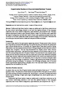
The unstrained model initial layout will use the same grid. But as the form-finding process is different than that of the strained gridshell, the grid will be given more division to have finer form. The boundary conditions are different for the unstrained gridshell as well. In all cases, it will be pinned in X, Y and Z directions (Figure 3.10 and Figure 3.10 ). Laths intersection is assumed to be free at local rotation and sliding in both models.
22 | P a g e
Gridshell structures in laminated bamboo
Methodology
Figure 3.10 Unstrained gridshell initial model boundary conditions (perspective) (Picture from Rhino3D)
Figure 3.8 Unstrained gridshell form finding, showing hanging chain-like-model (Picture from Rhino3D)
Figure 3.9 Unstrained gridshell form found geometry in compression (Picture from Rhino3D)
23 | P a g e
Gridshell structures in laminated bamboo
Methodology
3.4. Structural analysis 3.4.1. Unstrained The form found shape created using the process described in section 3.2.1, will be analysed in Karamba. Using default Grasshopper components, the data tree output from Kangaroo will be filtered to give the form found ‘Mesh’ data. The mesh is then discretized again to give separate lines which represent the actual laths of the gridshell. Lines, or laths, are curved as they represent prefabricated elements. These lines are then connected as beams to Karamba using ‘Line to beam’ components. Gravity loads, asymmetric loads, material properties, supports and the laths cross-section are then applied. These components are analysed together using the assemble component and then plugged into AnalyzeThI to be structurally analysed using first-order theory for small deformation.
3.4.2. Strained The form for strained gridshell is form found using the erection process for maximum bending moment, using Karamba as explained in section 3.2.2. The model is then disassembled and assembled again to be plugged into the second-order theory component AnalyzeThII for the second time, but with different loads. This step is important as it reflects the crucial visco-elasticity properties of bamboo (S. & S., 1997). Just like timber, when the gridshell is erected into place and then fixed, bending stresses that are built up while erecting will dissipate with time (Williams, et al., 2014). By disassembling the model, it’s assumed that the bending stresses are dissipated and now the laths don’t have any bending stresses in them. By assembling again, the model will take back its properties and loads can be applied to analyse deformation and stresses according to asymmetric loads. At this point, if no loads are applied, all bending moments and forces will be equal to 0.
3.5. Results analysis 3.5.1. Strained As it’s hard to bend steel members into place, strained steel gridshells will not be considered. Hence, comparison will be made only between western hemlock timber and laminated bamboo. Initially the maximum curvature that can be formed from the erection process will be compared. Also, the load that is required to lift the gridshells up will be compared. This is to compare the flexibility of each material and the feasibility of building with. After disassembling and assembling the structure the maximum deflections and load that can be carried by asymmetrical loading will be compared for both gridshells.
3.5.2. Unstrained After loads are applied to the form found geometry and the structure undergoes stressing, results can be obtained to feed the initial purpose of the research. For unstrained gridshells the maximum load the gridshell can take at this geometry will be compared between the three materials, western hemlock timber, laminated bamboo and steel. Maximum deflection resulting from the maximum load will also be compared. This is obtained using Karamba’s results components ‘Beam Forces’ and ‘Utilization of elements’.
24 | P a g e
Gridshell structures in laminated bamboo
Methodology
3.6. Summary To summarize, strained and unstrained methods will be using different tools to form find and will be using similar tools to structurally asses the structure. The strained model will use Karamba for both the erection process and analysis. The unstrained gridshell will use Kangaroo for form finding and Karamba for structural analysis. The procedure taken for this research’s method can be shown in Figure 3.11 and Figure 3.12. Unstrained
Strained
Target grid -Grasshopper default components
Target grid -Grasshopper default components
Target Shape -Kangaroo
Erection -Karamba
-Maximum curvuture -Target loads
-Required Load
-Materials -Cross sections -Supports -Target loads -Material -Cross section -Supports
Structural analysis -Karamba
Structural analysis -Karamba
-Maximum deflection -Maximum load
-Maximum deflection -Maximum load
Results evaluation
Figure 3.12 Unstrained Method procedures
Results evalutation
Figure 3.11 Strained Method procedure
25 | P a g e
Gridshell structures in laminated bamboo
4. STRAINED GRIDSHELL ANALYSIS AND RESULTS 4.1. Erection analysis As the loads (shown in Table 4.2) are applied at mid-span the gridshell is erected. The maximum load and maximum allowed bending moment is decided based on the materials’ bending strength. Both materials’ mechanical properties can be shown in Table 2.1. The maximum strength for each material is calculated according to the following equation: 𝐼 × 𝑀𝑂𝑅 × 10−6 = 𝑀𝑎𝑥𝑖𝑚𝑢𝑚 𝑎𝑙𝑙𝑜𝑤𝑎𝑏𝑙𝑒 𝑠𝑡𝑟𝑒𝑠𝑠 (𝑘𝑁𝑚) 𝑦 Where I is the section second moment of area in mm4, y is the distance to the outer fibre or position of centroid, and MOR is the modulus of rupture which is the bending strength of the material. Table 4.1 shows the maximum allowed bending moment in kNm for both materials.
Cross section
y
Bending Strength
Maximum allowable stress
I
mm
mm4
mm
MPa
kNm
Laminated Bambooa
50 x 50
5.21x10⁵
25
80
1.667
Western Hemlock
50 x 50
5.21x10⁵
25
49
1.021
Material
Table 4.1 Maximum bending stress calculations (for reference check Table 2.1)
As the load applied to the centre nodes results in bending stress close to the maximum bending stress, incremental load application is stopped and it can be said that the load is converged. The model’s is then analysed. In both cases bending failure will occur before buckling failure. Hence erection stops when maximum bending stress is reached. For this research, no safety factors are used. Maximum allowable stress
Applied load at 10 midspan nodes
Maximum bending in erected shape
Buckling load factor
Maximum height
Curvature smaller circle radius
Mass
kNm
kN (each)
kNm
BL>1 = safe
m
m
kg
Laminated Bamboo
1.667
1.1
1.59
1.14
2.337
3.28
391.0
Western Hemlock
1.021
0.7
1.00
1.17
1.977
3.95
287.5
Material
Table 4.2 Erection loads and curvature results comparison
26 | P a g e
Gridshell structures in laminated bamboo
Strained Gridshell analysis and results
The maximum curvature is analysed by Grasshopper’s default tools and presented visually. The height of each vertical line represents a higher curvature at that point. As expected, maximum curvature will be where the applied force is located. This happens at mid-span (shown in Figure 4.1). Also, the radius of the maximum curvature circle is taken to represent the maximum radius the laths can be bent before failing. As laminated bamboo can be bent more without violating the maximum bending stress, it can also reach higher magnitude at mid-span (Figure 4.2).
Figure 4.1 Front view of erected gridshell visualising maximum curvature as circle, erection loads and showing curvture graph (Picture from Rhino3D)
Figure 4.2 Curvature and height of both gridshells. (Blue) Laminated bamboo, (Red) Western Hemlock (Picture from Rhino3D)
27 | P a g e
Gridshell structures in laminated bamboo
Strained Gridshell analysis and results
4.2. Definition of asymmetric load As described in the methodology section and as shown in Figure 3.7, the erected gridshell is now in its final shape and pinned at all supports in X, Y and Z directions. Asymmetric loads and gravity loads are then applied to the final erected structure. Asymmetric loads will be defined as uniform loads applied to the surface area of the laths facing the load, in local to the element orientation. This will be applied to all elements. As shown in Figure 4.4 the load is acting in some cases as uplifting force and on other elements as contrary force. In both cases the loads is acting in the positive Y direction.
Figure 4.4 Load definition. Green arrows representing load. Blue lines represent the gridshell (Picture from Rhino3D)
Figure 4.3 Load definition. Perspective view. (Picture from Rhino3D)
28 | P a g e
Gridshell structures in laminated bamboo
Strained Gridshell analysis and results
4.3. Erected gridshell analysis All bending stress from erection are dissipated, therefore without applying any loads to the gridshell it will have no bending moments. As asymmetric loads are applied, defined in section 4.2, the gridshell deforms, and deformation and maximum load can be analysed.
Maximum allowable stress
Asymmetric load
Maximum bending
Buckling load factor
Maximum deflection
kNm
kN/m (each element)
kNm
BL>1 = safe
m
Laminated Bamboo
1.667
0.169
1.33
1.13
0.4579
Western Hemlock
1.021
0.147
1.04
1.17
0.4511
Material
Figure 4.5 Erected shape deflection and load results comparison
In both cases the maximum deflection is similar. This is expected as the shape is defined according to the maximum bending strength of both materials. Yet the maximum load both gridshells can resist is different. Laminated bamboo can take more load compared to western hemlock. Figure 4.6 shows the deformed shape of both gridshells after applying asymmetric loads. As laminated bamboo was bent into shorter span and taller height, it is shown in the figure as the higher curve.
Figure 4.6 Comparison of deformed shapes with stress colours
4.4. Discussion This analysis was made according to the bending maximum stress to show the peak strength of both gridshells. As shown in the previous section, it can be seen that laminated bamboo gridshells can be bent into higher curvatures. However, laminated bamboo gridshell will require higher loads than western hemlock, to be erected into shape. Also, laminated bamboo gridshells can reach higher without failing. Furthermore, stable laminated bamboo gridshells can resist 16% more asymmetric load than western hemlock timber, while deflecting the same distance. Generally western hemlock gridshells are also lighter then laminated bamboo ones. 29 | P a g e
Gridshell structures in laminated bamboo
5. UNSTRAINED GRIDSHELL ANALYSIS AND RESULTS In this section, the structural analysis and results of the unstrained gridshell will be looked at. Comparison between laminated bamboo, western hemlock and steel gridshell will be discussed. Deflections and the maximum load that can be resisted by the gridshell will be compared. All analysis will be performed on the form found shape, using dynamic relaxation, shown in Figure 3.9.
5.1. Definition of asymmetric load Loads for this case will be defined according to the global orientation. Uniformly distributed load (UDL) will be applied in the Z axis to all laths, as well as gravity load. The asymmetric load applied to the gridshell can represent constant pressure in the Z axis from any applied force. This can be snow, rain or wind loads.
Figure 5.1 Load definition for unstrained gridshell
5.2. Results Materials properties used for the analysis is the same from Table 2.1. Steel material properties can be found in Table 5.1.
Material
Western Hemlock
Density
Bending strength
Maximum allowable stress
Yield strength (fy)
kN/cm2
kN/m3
MPa
kNm
kN/cm2
8076
1.04
360
Young’s modulus (E)
Shear modulus (G)
kN/cm2 21000
7.5
27.5
Table 5.1 Steel material properties
30 | P a g e
Gridshell structures in laminated bamboo
Unstrained Gridshell analysis and results
Using the AnalyzeThI component, which analyses the structure using first-order theory for small deflections, the maximum load that can be applied until failure is investigated. Laminated bamboo reflects more strength in resisting loads by 45% than western hemlock. Deflection in laminated bamboo was 10% more than timber. Furthermore, steel reflects even higher strength, as expected, with 7-9 times more load resisting capacity than laminated bamboo and western hemlock and very minimal deflection of only 7.4cm.
Maximum allowable stress
Asymmetric load
Maximum bending
Maximum deflection
kNm
kN/m (each element)
kNm
(m)
Laminated Bamboo
1.667
4.3
1.629
0.276
Western Hemlock
1.021
2.7
1.021
0.235
Steel
7.500
19.6
7.500
0.074
Material
Table 5.2 Deflection and load results
5.3. Discussion Laminated bamboo again excelled over western hemlock timber in load resisting for unstrained gridshells. Also, laminated bamboo can resist twice the weight of western hemlock before failure. For the cost of fabricating steel laths and designing them, it’s not the most efficient method of building gridshells for its economic and environmental aspect over bamboo and timber.
Figure 5.2 Steel unstrained gridshell deformed shape (scale 4 times)
31 | P a g e
Gridshell structures in laminated bamboo
Unstrained Gridshell analysis and results
Figure 5.3 Western hemlock unstrained gridshell deformed shape (scale 4 times)
Figure 5.4 Laminated bamboo unstrained gridshell deformed shape (scale 4 times)
32 | P a g e
Gridshell structures in laminated bamboo
Conclusion
6. CONCLUSION This research has considered the application of laminated bamboo in building gridshells. Comparison between laminated bamboo and western hemlock timber was made to assess the viability of building gridshells in laminated bamboo. Different construction techniques of gridshells were tested to assess the gridshell in different conditions. First, an unstrained gridshell was tested using the three materials: laminated bamboo, timber, and steel. Then, a strained gridshell was evaluated to study the behaviour of erecting laminated bamboo gridshells compared to timber.
This research is based on a 10m by 10m gridshell, using 5cm by 5cm laths cross section. This is the same cross section used in the Mannheim Multihalle. For the unstrained method, the form was found using dynamic relaxation to find the funicular geometry for the grid. However, for the strained construction method, maximum material bending strength and buckling limit were used to limit the erection forces. In both techniques Grasshopper, along with Kangaroo and Karamba plugins, was used to form-find and structurally analyse the models. Non-linear analysis, second order theory for small deflections, and first order theory for small deflections were used as the fundamentals of Kangaroo and Karamba.
Bamboo trees can regrow without replacing their roots after being cut. The result is that bamboo forests have one quarter of the C02 density of spruce forests. Therefore, C02(e) is reduced by using Laminated bamboo in gridshells. Furthermore, Laminated bamboo has superior mechanical properties in compression and bending than timber. This was reflected in the research results as laminated bamboo surpassed timber performance in both unstrained and strained gridshells.
In strained gridshells, laminated bamboo can be erected to 20% more heights than western hemlock timber. Moreover, laminated bamboo can form 17% smaller curves. This shows the ability of laminated bamboo to form more rounded gridshells. This can give more freedom of designing free-form structures or double funicular gridshells. Also, laminated bamboo demonstrates its ability to reduce the cross section while performing structurally the same as timber. This can result in reduction of material usage, cost of the project and project time. The force required to erect laminated bamboo gridshells are 36% higher than those required to erect timber ones. This is due to the high density of laminated bamboo strips. Hence, western hemlock timber gridshells are lighter than laminated bamboo ones. Laminated bamboo gridshells, however, can resist 14% more asymmetric load laterally than western hemlock gridshells. Yet, both gridshells will have the same deflection under asymmetric load.
In unstrained gridshells, laminated bamboo again showed better performance than western hemlock timber. For its material flexibility, laminated bamboo gridshells deflects 15% more than timber under vertical asymmetric loading. Furthermore, they can resist 38% more vertical load than timber. As expected, steel,
33 | P a g e
Gridshell structures in laminated bamboo
Conclusion
however, can resist more load while deflecting less. Yet, the process of fabricating steel is more expensive than and not as sustainable as timer and bamboo.
Finally, the results suggest that it is feasible to make gridshell structures in laminated bamboo. The implication of these findings is that laminated bamboo gridshells can generally be formed into tighter curves while resisting higher asymmetrical loads and reaching higher. Furthermore, laminated bamboo gridshell represents more eco-friendly solution than timber gridshells.
Future Work This research confirms that laminated bamboo performs better than timber in the application of gridshells. Hence, further research can include experimental analysis with physical models to confirm the findings. Another natural continuation of the work could be the testing of different lattice formation. Also, more research can be done to test different cross sections and study the variation of building gridshells with thinner or thicker laths. Furthermore, the nature of laths connection can be further studied. This is to see the possibility of bamboo resisting shear and torsion at the laths intersections. Finally, hybrid gridshell of laminated bamboo and western hemlock timber can be studied. This is by having western hemlock laths at areas of low curvatures and long spans. Therefore, the structure will be lighter and more material efficient.
34 | P a g e
Gridshell structures in laminated bamboo
References
REFERENCES Adriaenssens, S., Block, P., Veenendaal, D. & Williams, C., 2014. Shell Structures for Achitecture. 1st ed. NY: Routledge. Architizer, 2015. Architizer. [Online] Available at: https://architizer.com/projects/zcb-bamboo-pavilion/ [Accessed 2 04 2017]. Chinese University of Hong Kong, S. o. A., 2015. ZCB Bamboo Pavilion. [Art] (www.Architizer.com ). Dickson, M. & Parker, D., 2015. Sustainable Timber Design. 1st ed. s.l.:s.n. Foster+Partners, 2000. Great court at the British Museum. [Art] (Foster + Partner). Green, D. W., Winandy, J. E. & Kretschmann, D. E., 2010. Mechanical Properties of Wood. In: Wood Handbook - Wood as an engineering material. Madison(Wisconsin): U.S. Department of Agriculture , pp. 5-4 - 5-7. Happold, E. & Liddell, I., 1975. Timber lattice roof for the Mannheim Bundesgartenschau. Instituation of Structural Engineers, 53(3), pp. 99-133. Harris, R., 2005. The age of enlightenment for timber design Part 2: Environmental credentials. In, 2005. Institution of Structural Engineers, 23-28.. The Structural Engineer, 83(2), pp. 23-28. Harris, R., 2006. Savill Building: A new landmark for Windsor Great Park.. Structural Engineer, Volume 84, pp. 16-19. Harris, R. & Roynon, J., 2008. The Savill Garden gridshell:Design and construction. The Structural Engineer, 86(17), pp. 27-34. Heyman, J., 1977. Equilibrum of Shell Structures. 1st Edition ed. Oxford: Oxford University Press. Naicu, D., Harris, R. & Williams, C., 2014. Timber gridshells: Design Methods and their application tot a temporary pavilion. Quebec city, World conference on Timber Engineering (WCTE). Naicu, D. L., 2012. Geometry and Performance of Timbr Gridshells, Bath: The University of Bath. Ochsendorf, J. & Block, P., 2014. Exploring shell forms. In: Shell Structures for Architecture form finding and Optimization. NY: Routledge, pp. 7-12. Orr, J., 2015. Examples of effective Length. In: Structures 1B. Bath: University of Bath, p. 208. Otter, J. R. H., Cassell, A. C., Hobbs, R. E. & Poisson, 1966. Dynamix relaxation. ICE, 35(4), pp. 633-656. Princeton University , 2013. Mannheim Multihalle. [Online] Available at: http://shells.princeton.edu/Mann1.html [Accessed 17 12 2016]. Rockwood, D., 2015. Bamboo Gridshells. 1st ed. NY: Routledge. S., A. & S., L. R., 1997. Viscoelastic properties of bamboo. [Online] Available at: http://silver.neep.wisc.edu/~lakes/VEbamboo.pdf [Accessed 1 4 2017]. 35 | P a g e
Gridshell structures in laminated bamboo
References
Salinas, J. G. O., Rocha, X. C., Olmedo, E. V. & Cortina, A. C., 2011. “Bamboo - Otate” A Renewable Material for Lightweight Structures, Mexico: Universidad Nacional Autónoma de México, UNAM. Schlaich, J., 2014. On architects and engineers. In: Shell structures for Architecture. NY: Routledge, pp. VIIIXI. Schlaich, J. & Schlaich, M., 2017. Lightweight structures. [Online] Available at: https://architecture.mit.edu/sites/architecture.mit.edu/files/attachments/lecture/Lightweight Structures.pdf Sharma, B., Bauer, H., Schickhofer, G. & Ramage, M. H., 2016. Mechanical cahracterisation of structural laminated bamboo, s.l.: ICE Publishing . Sharma, B. et al., 2014. Engineered bamboo: state of the art. Construction Materials , 168(2), pp. 57-67. Sharma, B., Gatóo, A., Bock, M. & Ramage, M., 2015. Engineered bamboo for structural applications. Construction and Building Materials, 15 April, Volume 81, pp. 66-73. Williams, C., 2014. The Multihalle and The British Museum. In: S. Adriaenssens, P. Block, D. Veenendaal & C. Williams, eds. Shell structures for architecture . NY: Routledge , pp. 239-244. Williams, C., Barnes, M., Harris, R. & Adriaenssens, S., 2014. Dynamic relaxation. In: Shell structures for architecture. NY: Routledge, pp. 89-101. Zenbamboo, 2017. Raw Bamboo. [Art] (Made In China).
36 | P a g e