BLDC motors have been popular in various industrial applications and electric mobility. In most brushless direct current (BLDC) motor drives, there are three hall ...
MATEC Web of Conferences 59, 01007 (2016)
DOI: 10.1051/ matecconf/20165901007
IC FS T 2016
Hall Sensor Output Signal Fault-Detection & Safety Implementation Logic 1
SangHun, Lee , HongSeuk, Oh 1 2
2
Intelligent automotive team, Daegu Mechatronics & Materials Institute, S.Korea 2STARGROUPIND. LTD, S.Korea
Abstract. Recently BLDC motors have been popular in various industrial applications and electric mobility. Recently BLDC motors have been popular in various industrial applications and electric mobility. In most brushless direct current (BLDC) motor drives, there are three hall sensors as a position reference. Low resolution hall effect sensor is popularly used to estimate the rotor position because of its good comprehensive performance such as low cost, high reliability and sufficient precision. Various possible faults may happen in a hall effect sensor. This paper presents a fault-tolerant operation method that allows the control of a BLDC motor with one faulty hall sensor and presents the hall sensor output fault-tolerant control strategy. The situations considered are when the output from a hall sensor stays continuously at low or high levels, or a short-time pulse appears on a hall sensor signal. For fault detection, identification of a faulty signal and generating a substitute signal, this method only needs the information from the hall sensors. There are a few research work on hall effect sensor failure of BLDC motor. The conventional fault diagnosis methods are signal analysis, model based analysis and knowledge based analysis. The proposed method is signal based analysis using a compensation signal for reconfiguration and therefore fault diagnosis can be fast. The proposed method is validated to execute the simulation using PSIM.
1 Introduction Recently BLDC motors have been popular in various industrial applications and electric mobility. The BLDC motor is a DC motor type that has no brushes; therefore commutation is done electronically according to the permanent magnet rotor position based on the hall sensor signal. Correct commutation and control of BLDC motors depend on the exact position detection of rotor. Sensors such as optical encoders, for high resolution applications, and hall effect sensors, for low resolution applications, are normally used to detect position of the permanent magnet rotor. Rotor position detection techniques in sensorless control drives of the BLDC motor are mainly based on back-EMF sensing, back-EMF integration, free-wheeling diode conduction of the unexcited phase, flux linkage of motor, and third-harmonic analysis of back-EMF.
Reduction of the BLDC motor manufacturing cost, the motor maintenance and possibility of the motor malfunctions due to failure or unbalanced positioning of sensors are advantages of sensorless control techniques; however difficulties of back-EMF sensing at low speeds and transient time, complexity of rotor detection algorithms and discontinuous response due to high commutation rates are the main drawbacks of sensorless techniques. Low resolution hall effect sensor is popularly used to estimate the rotor position because of its good comprehensive performance such as low cost, high reliability and sufficient precision. However various possible faults may happen in a hall effect sensor such as flaws in the core (corrosion, cracks, residual magnetic fields and core breakage), changes in the bias current, change in the magnetic properties of the ferrite core due to temperature variations, changes in the orientation of the induced magnetic field in the sensor (due to mechanical shocks or other reasons). Any of these faults may result to breakdown of the hall effect sensor in BLDC motor. There are a few research work on hall effect sensor failure of motor. Signal analysis, model based and knowledge based methods are the main techniques for fault diagnosis in the BLDC or PMSM drives[1]~[8]. In the signal analysis based methods, fault is detected and identified through comparison of the BLDC motor signals with the ideal situation. Therefore there is no need for an accurate dynamic model of the motor. Signal analysis fault diagnosis methods are generally slower than other two methods. Fault diagnosis in model based
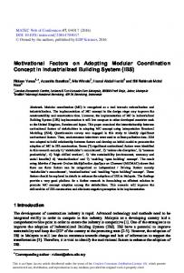
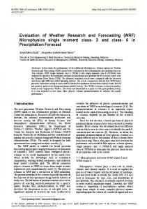
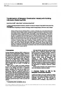
Figure 1. BLDC motor applications in E-mobility
© The Authors, published by EDP Sciences. This is an open access article distributed under the terms of the Creative Commons Attribution License 4.0 (http://creativecommons.org/licenses/by/4.0/).
MATEC Web of Conferences 59, 01007 (2016)
DOI: 10.1051/ matecconf/20165901007
IC FS T 2016
methods is quite fast and can be used for online fault detection; however the exact mathematical model of the BLDC motor is needed. Model based observers are popularly used in fault diagnosis systems; however fault detection residuals are influenced not only by system faults but also by disturbances and model uncertainties. Since uncertainties, disturbances or noise in system are unknown and cannot be modelled mathematically; therefore there is always a difference between the mathematical model results and actual system performance that can generates false fault detections in model based systems. In expert systems, fuzzy or neural network controllers are developed based on the knowledge of system. The knowledge is collected and analysed either through an experienced engineer with a thorough understanding of the system, or via comprehensive study of the system dynamics through a validated simulation model. In this paper, the hall sensor output fault-tolerant control strategy based on signal analysis and the proposed compensation logic is suggested.
2 Conventional Hall Tolerant Strategy
Sensor
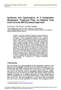
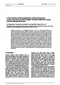
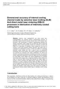
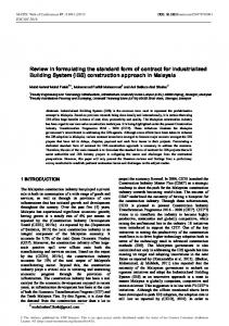
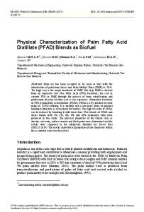
Hall Effect sensors are mounted inside the BLDC motor with 120 electrical degree phase difference to detect rotor position. Output of each sensor is high (logic ’1’) for 180 electrical degree and is low (logic ’0’) for the next 180 degree with respect to rotor position. Each Hall Effect signal of BLDC motor has specific value at each instant of time with respect to permanent magnet rotor position. Electronic commutation is done by decoding the position sensor signals. Decoding Hall Effect signals result to choose the proper voltage space vector for switching of the three phase Voltage Source Inverter (VSI) drive of BLDC motor. Fig. 2 shows the schematic diagram of 3 phase Y – connected BLDC motor and three phase VSI drive and Fig. 3 shows the output signal according to hall sensor configurations.
Fault-
To rotate the BLDC motor, the stator windings should be energized in a sequence. It is important to know the rotor position in order to understand which winding will be energized following the energizing sequence. Rotor position is sensed using Hall effect sensors embedded into the stator. Most BLDC motors have three Hall sensors embedded into the stator on the non-driving end of the motor. Whenever the rotor magnetic poles pass near the Hall sensors, they give a high or low signal, indicating the Nor S pole is passing near the sensors. Based on the combination of these three Hall sensor signals, the exact sequence of commutation can be determined.
Figure 3. Output signal according to hall sensor configurations
In general, fault tolerant control systems are responsible to detect and identify the hall sensor fault condition and fault safety logic is used to isolate the faulty section and take the appropriate remedial action to keep the system working under the fault condition. The conventional fault diagnosis methods are signal analysis, model based analysis and knowledge based analysis. As mentioned above, in signal based method, fault is detected and identified through comparison of the ideal signals. Therefore motor dynamic model isn’t needed but fault diagnosis is slow. And in model based analysis, fault is detected and identified through mathematical model & model observer. So motor dynamic model is needed but fault diagnosis is fast. The proposed method is signal based analysis using a compensation signal for reconfiguration and it has two steps for checking fault conditons. Step 1. Pre-Fault condition detection and identification of the falut. Step 2. Post-Fault condition isolation of the falut & take action for motor operation
Figure 4. Hall Sensor Fault-Safety Strategy
Figure 2. Schematic Diagram of BLDC motor drive
2
MATEC Web of Conferences 59, 01007 (2016)
DOI: 10.1051/ matecconf/20165901007
IC FS T 2016
The proposed fault-detection and fault-safety logic is programmed by C-block function and the mentioned algorithm has the following main block :
3 The proposed Hall Sensor FaultTolerant Strategy As mentioned above, the basic concept is the same with the conventional signal based method. So the operation rule check of hall sensor signal and switching sequence is shown in Fig 5 and Table 1.
1) hall sensor output decoding block 2) hall sensor output fault-detection block 3) hall sensor output fault-isolation block 4) hall sensor output reconfiguration block Simulation condition has one hall fault condition of three hall sensors under motor operation at 3000 rpm and the proposed alogrithm does not allow start-up and near zero speed operation of a BLDC motor. Because it is impossible to measure the pulse length on the other two hall sensors when the motor does not rotating.
Figure 5. BLDC commutation diagram (Hall Sensor I/F)
Table1 1. Hall Sensor Output Signal Decoding Rules
The related equation for operation rule check is the following that : (1) here,
weight value (n : 4, 2, 1)
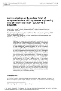
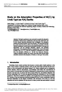
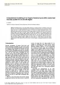
Figure 6. Output Signals due to One Hall Sensor Fault
In normal condition, the output of has the sequential value according to the rotor position. But in the fault has not the normal sequential condition, the output of value because one of three has constant “0” or “1” despite of motor rotation like Fig 6. In case of one hall seonsor fault, it occurs that XOR of three hall sensors and the decoding rules of hall sensor output signal are changed. The proposed method is shown in Fig 6. The fault detection is executed by equation (1) and XOR logic pulse train based on three hall signal output. If the fault condition is occurred, the XOR logic duty is non symmetric and it can be detected as a fault. The reconfiguration signal is made by XOR logic and the other two hall sensor output like Fig 6.
4 Simulation Results In order to verification, Powesim is used to simulate the proposed hall sensor fault-tolerant strategy. Figure 7. Proposed Hall Sensor Fault-Safety Strategy
3
MATEC Web of Conferences 59, 01007 (2016)
DOI: 10.1051/ matecconf/20165901007
IC FS T 2016
Conclusion In this paper, the hall sensor output fault-tolerant control strategy based on signal analysis and the proposed compensation logic is suggested. The main logic that allows the operation of BLDC motor drive with one faulty hall position sensor is proposed. Fault condition is detected when the hall sensor holds continuously at the low or high level. The proposed algorithm was verified by PSIM. As a result, it is shown that the proposed method can execute fault-detection and reconfiguration within 1 electrical cycle and therefore it has very short of reaction time and no interference for motor operation. But the proposed method does not allow start-up and near zero speed operation of a BLDC motor, because it is impossible to measure the pulse length on the other two hall sensors when the motor does not rotating.
Figure 8. Simulation Schematics based on PowerSim
Acknowledgement This project is supported and funded by DaeguKyoungbuk Institute for Regional Program Evaluation in 2015. Special thanks for STARGROUP INDUSTRY LTD in South of Korea.
References 1.
2.
3.
4.
5.
6. Figure 9. Simulation results
Fig. 9 shows the simulation results. As mentioned above, the operation rule check is executed to detect the fault condition. When fault is occurred by one of three hall sensor, the other two hall sensor output and count pulse train are used to rebuild the proper signal. The proposed method can execute fault-detection and reconfiguration within 1 electrical cycle like Fig. 9 and therefore it has no interference for motor operation.
7.
8.
4
X.-Q, �Fault detection & diagnosis of pm dc m-otor based on parameter estimation & neural net-work�, IEEE transactions on Industrial Elec., Vol.47, no. 5, pp.1021-1030, 2000 S. Mondal, �Unknown input high gain observer for fault detection & isolation of uncertain system� , Engineering Letters, vol.17, no.2, pp.121-127,2009 A. Tashakori, “A Simple Fault Tolerant Control System for Hall Effect Sensors Failure of BLDC Motor,” IEEE 8th Conference on industrial Electronics and Applications, 2013 N. Rajendran, “A Control Reconfiguration Strategy for Hall Sensor FTC in BLDC Motor,” International Journal of Scientific & Engineering Research, Vol.5, Issue 4, April, 2014 Song Ziyou, “Rule-Based Fault diagnosis of Hall Sensors and Fault-Tolerant Control of PMSM” Chinese Journal of Mechanical Engineering, Vol.26, Issue 4, 2013 Z. Wang, R. Schittenhelm, M. Borsdorf, and S. Rinderknecht, “Application of augmented observer for fault diagnosis in rotor systems,” Engineering Letters, vol. 21, no. 1, pp. 10–17, 2013. Y.-S. Jeong, S.-K. Sul, S. Schulz, and N. Patel, “Fault detection and faulttolerant control of interior permanent-magnet motor drive system for electric vehicle,” IEEE Transactions on Industry Applications, vol. 41, no. 1, pp. 46–51, 2005. L. Wang, J. Liu, and X. Wu, “Fault analysis on driving motors of lunar rover wheels,” in Proceeding of the International Conference on Electrical Machines and Systems, ICEMS 2011, (Beijing, China), Aug 2011.